Spatially coherent surface resonance states derived from magnetic resonances
Abstract
A thin metamaterial slab comprising a dielectric spacer sandwiched between a metallic grating and a ground plane is shown to possess spatially coherent surface resonance states that span a large frequency range and can be tuned by structural and material parameters. They give rise to nearly perfect angle-selective absorption and thus exhibit directional thermal emissivity. Direct numerical simulations show that the metamaterial slab supports spatially coherent thermal emission in a wide frequency range that is robust against structural disorder.
pacs:
78.67.Pt, 42.70.Qs, 44.40.+a, 42.70.KmI Introduction
Surface plasmon polaritons (SPPs) can modulate light waves at the metal-dielectric interface with wavelength much smaller than that in free space1 ,which enables the control of light in a subwavelength scale for nanophotonic devices2 . SPPs with large coherent length are useful in many areas, including optical processing, quantum information3 and novel light-matter interactions4 . The enhancement of local fields by SPPs is particularly important as it opens a new route to absorption enhancement5 , nonlinear optical amplification6 ; 7 as well as weak signal probing8 ; 9 . As the properties of SPP are pretty much determined by the natural (plasmon) resonance frequency, there is not much room for us to adjust the SPP response for practical applications. With induced surface current oscillations on an array of metallic building blocks10 ; 11 ; 12 ; 13 ; 14 ; 15 ; 16 , metamaterial surfaces can manipulate electromagnetic waves in a similar way as SPPs. Such SPPs or surface resonance states on structured metallic surfaces are tunable by geometric parameters.
In this paper, we examine the properties of surface resonance states at a dielectric-metamaterial interface that exhibit magnetic response to the incident waves and strong local field enhancement. We will see that these surface resonance states can give highly directional absorptivity and emissivity, and may thus help to realize interesting effects such as spatially coherent thermal emission. As the structure is very simple, it can be fabricated down to the IR and optical regime17 ; 18 ; 19 .
We will show that a thin metamaterial slab, with a thickness much smaller than the operational wavelength, supports delocalized magnetic surface resonance states with a long coherent length in a wide range of frequencies. Operating in a broad frequency range, these spatially coherent SPPs are surface resonance states with quasi-TEM modes guided in the dielectric layer that are weakly coupled to free space, and the coupling strength can be controlled by tuning structural parameters while the frequency can be controlled by varying structural and material parameters. The high fidelity of these surface resonance states results in directional absorptivity or emissivity, which is angle-dependent with respect to frequency. Finite-difference-in-time-domain (FDTD) simulations verify that the highly directional emissivity from the slab persists in the presence of structural disorder in the grating layer.
Such metal-dielectric-metal (MDM) structures were recognized as artificial magnetic surfaces with high impedance by the end of last century12 , the magnetic response were described with an effective permeability in Lorentz type12 ; 20 . After the concept of metamaterial being proposed21 , P. Alastair and his co-workers numerically and experimentally proved that the ultra-thin MDM structures can resonantly absorb or transmit radiations at low frequency limit[22]. They addressed that the central frequencies of absorption peaks are independent from the incident angle with an interpretation of Farby-Perrot resonant mode (EQ. 1 in Ref. 22). The same group further explored the angle-independent absorption, as the main scenario of the incremental work, by measuring the flat bands of surface wave dispersion in the visible23 as well as the microwave region24 . In contrast, we find that the structure with proper design also supports very narrow absorption peaks which are sensitive to the incident angle and obviously do not satisfy to the Fabry-Perot resonance condition suggested in the previous studies.
It is worth noting that the physics origin of an angle-independent peak is quite different from that of angle-dependent ones. The former, investigated in Refs. 22-24, mainly comes from the localized surface resonance states, while the latter, found by us, comes from collective surface resonance states. An intuitive picture is as follows: high order quasi-TEM modes induced inside the dielectric layer can assign phase correlation to the outgoing waves emitted from the air slits of grating, thus are very crucial to the formation of collective response. Weak enough both the leakage from dielectric layer to air slits and the material absorption, the spatial coherence of surface resonance states will survive. As the interaction between the structure and the incident waves will excite quasi-TEM modes inside the dielectric layer, the magnetic induction must be parallel to the MDM surfaces if it exists. Thus a surface resonance state on a MDM structure is usually magnetic in nature. Our findings about spatially coherent surface resonance states are original compared to the common knowledge, and have great potentials in coherent control of SPPs as well as thermal emission radiations.
II Model Description and Mode Expansion Method
Our model system is schematically illustrated in Fig. 1. Lying on the plane, the slab comprises an upper layer of a metallic lamellar grating with thickness , a dielectric spacer layer as a slab waveguide with thickness and a metallic ground plane. The metallic strips are separated by a small air gap , giving rise to a period of for the lamellar grating. Each metallic strip together with the ground plane beneath it constitutes a planar resonant cavity as the building block that gives magnetic responses at cavity resonances12 ; 16 . The metallic grating is along the direction so that the guided waves in the dielectric layer (at in region III) can only couple with the transverse magnetic ( polarized wave (with the electric fieldin plane) in the free semi-space (at in region I). The geometric parameters of our model are m, m, m, m and m.

For a TM incident plane wave with an in-plane wave vector , the EM field in region I and in region III can be written in terms of the reflection coefficients and the guided Bloch wave coefficients 25 ; 26 ; 27 ; 28 , as
| (1) |
where the term denotes the incident plane wave with , being the Kronecker function and being the Bloch order; denotes wave component of the Bloch eigenmode in the semi-free space (region I) and the dielectric layer (region III) with respect to . is the in-plane wave vector and is the reciprocal lattice vector. and are the components of wave vector for the order Bloch eigenmode in region I and region III respectively. and are the permittivity of the vacuum and the dielectric slab, is the vacuum permeability.
We shall mainly consider infrared frequencies, at which the metals can be well approximated as perfectly electric conductors (PEC). The EM fields at in region II are squeezed inside the air gaps, in which the magnetic fields can be expressed in terms of the expansion coefficients and of forward and backward guided waves, as:
| (2) |
where , is the in-plane distribution of guided mode running over all air gaps defined by29 . is the z component of wave vector for the guided mode .
We can obtain the coefficients and of the guided and reflected waves by applying the boundary continuity conditions for the tangential components of electromagnetic wave fields (over the slits) at the interfaces and . Given that surface resonance modes are intrinsic response, we can also assign zero to the incident plane wave and apply the boundary continuity conditions for the tangential components of wave fields to derive the eigen-value equations. A surface resonance state can be determined by searching a zero value/minimum of eigen-equation determinant in the reciprocal space provided that it is non-radiative/radiative with infinite/finite life time below/above light line in free space.
III ABSORPTION SPECTRA PROPERTIES AND SPACIAL COHERENCE OF MAGNETIC SURFACE RESONACE STATES
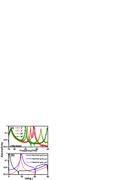
We derived the absorption spectra of the slab which includes the contributions from all Bloch orders of reflected waves. As a consequence, gives information about the surface resonance states as well as the emissivity properties as governed by Kirchhoff’s law30 . We shall assume that the dielectric spacer layer is slightly dissipative by assigning a complex permittivity with and S/m [] in the calculated frequency regime. In Fig. 2(a), we present the absorption spectra at various incident angles. The spectra exhibit a low and broad peak at THz which is almost independent of the incident angle, while the other absorption peaks at higher frequencies are narrow and sensitive to the incident angle with a maximum absorption approaching 100%. The slab thus acts as an all-angle absorber at THz (a similar result can be found in Ref. 31), but exhibits sharp angle-selective absorption peaks at higher frequencies. Shown as solid and dashed lines in Fig. 2(b), the sharp angular dependence of absorption coefficients (note that the vertical axis is in log-scale) at THz and 54.3THz implicitly implies the existence of spatially coherent surface resonance states. The angle-dependent absorption peaks become lower and disappear gradually with the increase of the material loss. This presents a way to realize nearly perfect absorption with weakly absorptive materials by coherent surface resonance states. The coherent length of a surface resonance state can be estimated by the ratio of the wavelength and the full width at half maximum (FWHM) of the absorption peak32 . For example, for the state at 54.3THz and , the angular FWHM of the corresponding absorption peak (from to gives rise to a coherent length . The coherent length is about for the surface resonance state at 50.22THz and with (not shown in figure). The angular FWHM is reduced if the gap size is smaller, as shown with the dashed and dotted lines in Fig. 2(b) for m and m at 40THz, which means that the coherent length of the surface resonant modes can be controlled by the gap-period ratio .
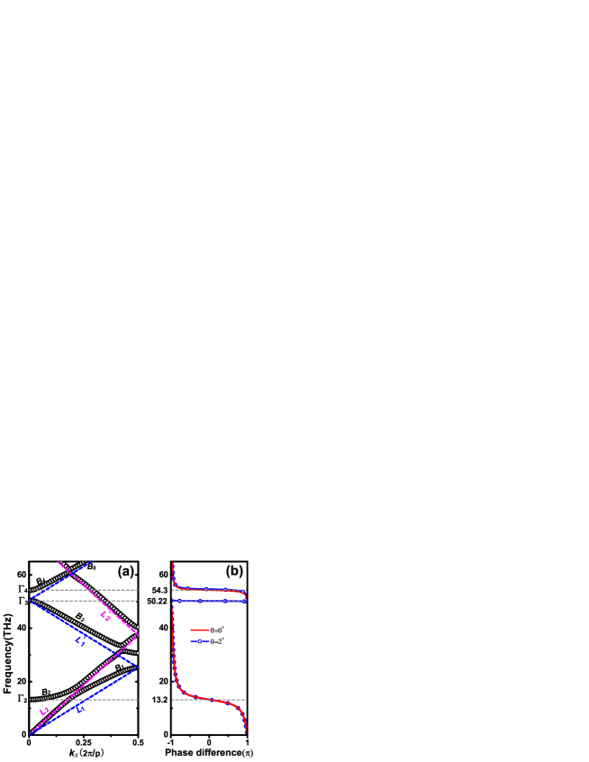
To quantitatively characterize the formation of these spatially coherent surface resonance states, we employ the eigenmode expansion method to calculate the surface resonance dispersion (in the limit of no material loss) as shown in Fig. 3(a). The surface resonance states lie blow the light line (magenta dashed line), and thus are non-radiative as evanescent modes. The surface resonances labeled as originate from the coupling of the fundamental magnetic resonance modes of the metal strip structure with the free space light line . The surface resonances and are harmonic modes of the magnetic resonances that hybridizes with the guided mode inside the dielectric layer. The calculated reflection phase difference between the 0th order reflected and incident electric field, as shown in Fig. 3(b) for normal incidence(red line), and incidence(blue line), clearly shows that the resonances are magnetic in nature when the surface resonances intersect the zone center at (13.2THz ) and (54.3THz) as the reflection phase is zero like what a magnetic conductor surface does to the incident waves. The state , invisible in the reflection phase spectrum under normal incidence [red solid line in Fig. 3(b)], is a dark state as its eigenmode is in mirror symmetry about the plane and can not couple with free space photons. While the other states can couple with external light under oblique incidence [see the blue line in Fig. 3(b)]. For example, there exists in-phase reflection at frequency 50.22THz under an incident angle of 2, corresponding a state at frequency 50.22THz and .
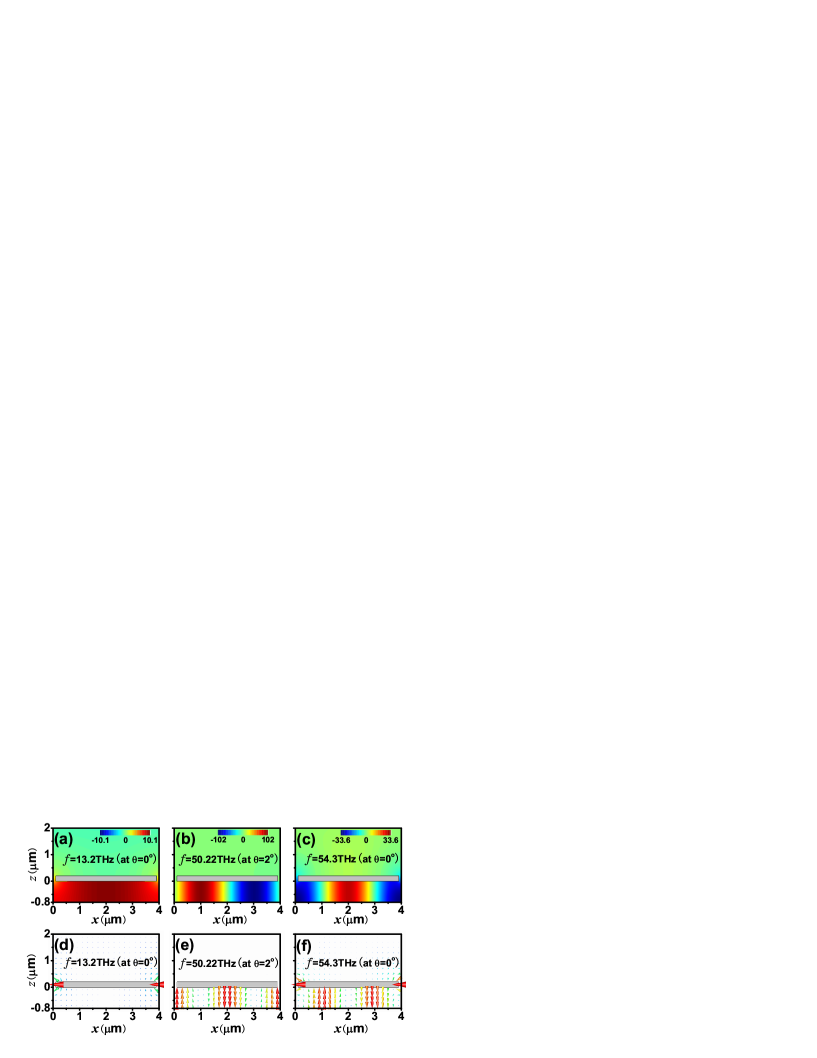
The angle-independent absorption peak at 13.2THz is due to the mode, which is only weakly dispersive near the zone center. The more dispersive and modes are accountable for the incident-angle sensitive absorption in the higher frequencies in Fig. 2(a). The field patterns in Figs. 4(a)-4(c) present the spatial distribution of the real part of magnetic fields excited by the incident plane waves with incident angles , and for the three surface resonance states on , and respectively, and the corresponding vector diagrams of electric fields are shown in Figs. 4(d)-4(f). We can see clearly that the electric fields reach maximum in strength at the slab upper surface, and exponentially decay along the surface normal into the free space. This is precisely a picture of SPP modes. The field patterns comes from the coincidence of the evanescent wave components in high Bloch orders at both sides of metallic grating.

Although only TEM guided modes are allowed to be excited in the thin MDM slab within the frequency of our interest, the states are quite different from the and states in field patterns inside the dielectric layer. We see from Figs. 4(b), 4(c) ,4(e)and 4(f) that for a or state, there are nodes and anti-nodes in field patterns, while for the state, the magnetic field is almost uniformly distributed. Calculations on local field enhancement inside the dielectric slab resolve the puzzle. Black solid line in Fig. 5 presents the normalized magnetic field inside the dielectric with respect to that of incidence under an incident angle of . The Fourier component in order [blue solid line] contributes the most at 13.2THz and the least at 50.22THz and 54.3THz; while it is just opposite for the contributions in combination from the two high order Fourier components with m= orders[red solid line]. Figure 5 also indicates that the enhancement of local field of an excited or state can be ten times larger than that of an excited state; the enhancement factor at 50.22THz is about 100, while it is only 10 at 13.2THz.
We see from Fig. 3(a) that the surface resonance dispersion of the slab comes from the interaction between the magnetic resonances and the (folded) light lines (for dielectrics) and (for air) grazing on the interfaces. In the limit of a small gap-period ratio ( for example), our system is weakly Bragg-scattered, and as such, when a surface resonance state on branches or is excited, the induced wave fields inside the dielectric of region III are guided quasi-TEM modes dominated by Bloch orders. For that reason, the and states have high fidelity even though they are leaky modes, as most of their Bloch wavefunction components lying outside the free space light line. As the air gaps of the metallic grating serve to couple the electromagnetic waves of region I and region III, the quality factor of a resonance state can be estimated with the overlap integral between the fundamental waveguide mode in the air gap and the dominant Bloch waves ( in region I or region III for the coupling coefficients
| (3) |
when the air gap width is satisfied. For the states, the major Fourier component of the wavefunction is in zero order, and as is generally not small, is usually very large according to Eq. 3, and the states leak out easily. The states on branches and have major Fourier components in m= order, and as they are asymptotic to the (folded) dielectric light lines , the absolute value of ( for or for is very small, resulting in the small coupling coefficients or . The and modes have to travel a long distance before they leak out. They have a long life time and a good spatial coherence. It also explains why the state , a state precisely superposing on folded light line in dielectric layer, is dark to the incident plane wave as .
Different from and states, the states have a major Fourier component in order which directly couples to the free space photons. As a consequence, the states, forming a flat band far away from the light line when is small, are localized with resonant frequency scaled by local geometry of unit cell. The high model fidelity of a or state also gives rise to much more intense local field compared to the states. As shown in Fig. 5, the induced local field is 100 times stronger than the incident field for the state on ; while it is only 10 times stronger for , and this is consistent with the absorptivity shown in Fig. 2(a). In addition, the coherent length can be adjusted by the gap width as the kernel is proportional to the gap-period ratio . More calculations demonstrate that the angular FWHM of the absorption peak is reduced from to when the gap is decreased from m to m, corresponding to a coherent length of .
We note that most of the attentions in previous studies have been devoted on the localized states22 ; 23 ; 24 ; 31 . While the spatially coherent surface resonance states will lead us into a new vision about coherent control of emission radiations. J.-J. Greffet and co-workers showed that highly directional and spatially coherent thermal emission can be obtained by etching a periodic grating structure into a SiC surface32 ; 33 ; 34 ; 35 . The magnetic resonant modes in our system can do the same, as will be demonstrated below. Our system has the advantage that the operational frequency is tunable by changing the structural parameters, and the operational bandwidth is wide. In addition, our structure supports all-angle functionality for some specific range of frequencies as shown in Fig. 6, although it is periodic only in one direction.
IV Coherent Thermal Emission
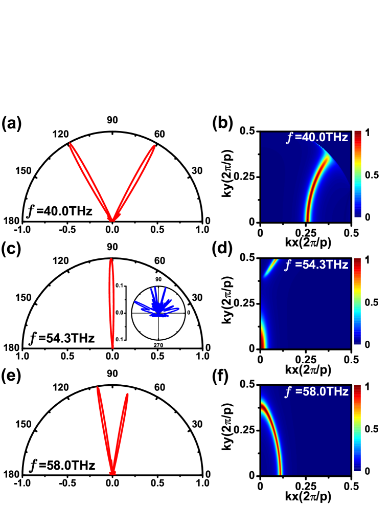
We performed finite-difference-in-time-domain (FDTD) simulations to emulate the emissions from a slab containing point sources with random phases using the same configuration parameters aforementioned. We purposely put disorder in structure to test the robustness of the phenomena. We assigned two Gaussian distributions(they can be uniform distributions or other types as well) independently to the width of metallic strips and the center positions of air gaps to introduce a 4% (standard deviation) structural disorder. The slab has a lateral size of 60 periods along the direction. A total of 1200 point sources with random phases are placed at the mesh points inside the dielectric layer. Directional emissions of a wide range of frequencies above THz are confirmed by the simulation. The 4% structural disorder has little impact on the directional emissivity. Figs. 6 (a), 6(c) and 6(e) show the far-field emission patterns in the plane (H-plane) at 40.0THz, 54.3THz and 58.0THz. The inset in Fig. 6(c) is a control calculation in which the top metal gratings are removed, so that there is just a dielectric layer with random phase sources above a metal ground plane. The directivity of emission from the random sources is lost. Figs. 6(b), 6(d) and 6(f) present the absorptivity (under plane wave incidence) as a function of in-plane wave-vector (solid angle) at these frequencies. The strong angle selectivity of the absorption is evident, and by Kirchhoff’s law, the thermal emission should also be highly directional, which is a direct consequence of the good spatial coherence of the surface resonance states. As shown in Figs. 6(b), 6(d) and 6(e), the absorption/emission peaks generally trace out an arc in the plane, but near THz[Fig. 6(d)], the dominant emission beam is restricted to a small region near the zone center. This is because the state is a minimum point if we consider the band structure in the plane. That means that at 54.3THz, we can obtain a directional emission beam not just in the H-plane, but in all directions, although the structure is periodic in only one direction.
We note that there are other schemes to realize coherent thermal radiations, such as by utilizing three-dimensional photonic crystals36 or one-dimensional photonic crystal cavities37 . Our metamaterial slab presents a route to achieve linearly polarized coherent thermal emission radiations in a wide frequency range which can be tuned by adjusting structural parameters and material parameters.
V Conclusion
In summary, we proposed a simple metamaterial slab structure that possesses spatially coherent magnetic surface resonance states in a broad range of frequencies. These states facilitate nearly perfect absorption in a thin metamaterial slab containing slightly absorptive materials. As the absorption spectrum is highly angle-selective, the slab should give directional thermal emission. Direct FDTD simulation with random-phase sources corroborates the existence of strong angular emissivity even in the presence of structural disorder. As the surface resonances originate from artificial resonators, the operational frequency and the response can be tuned by varying the structural configurations. The simple metamaterial structure may be a useful platform to realize the coherent control of thermal emissions, optical antennas, infrared or THz spectroscopy as well as photon detector.
VI Acknowledgment
This work is supported by the National 863 Program of China (Grant No. 2006AA03Z407), NSFC (Grant No. 10974144, No. 60674778), CNKBRSF (Grant No.2006CB921701), HK RGC grant 600308, NECT, STCSM and Shanghai Education and Development Foundation (No. 06SG24).
References
- (1) Raether H 1988 Surface Plasmons on Smooth and Rough Surfaces and on Gratings (Berlin: Springer-Verlag)
- (2) Barnes W L, Dereux A and Ebbesen T W 2003 Nature 424 824-30
- (3) Kamli A, Moiseev S A and Sanders B C 2008 Phys. Rev. Lett. 101 263601
- (4) Vasa P, Pomraenke R, Schwieger S, Mazur Y I, Kunets V, Srinivasan P, Johnson E, Kihm J E, Kim D S, Runge E, Salamo G and Lienau C 2008 Phys. Rev. Lett. 101 116801
- (5) Andrew P, Kitson S C and Barnes W L 1997 J. Mod. Opt. 44 395-406
- (6) Coutaz J L, Neviere M, Pic E and Reinisch R 1985 Phys. Rev. B 32 2227-32
- (7) Tsang T Y F 1996 Opt. Lett. 21 245-7
- (8) Kneipp K, Wang Y, Kneipp H, Perelman L T, Itzkan I, Dasari R R and Feld M S 1997 Phys. Rev. Lett. 78 1667-70
- (9) Nie S and Emory S R 1997 Science 275 1102-6
- (10) Pendry J B, Holden A J, Stewart W J and Youngs I 1996 Phys. Rev. Lett. 76 4773-6
- (11) Pendry J B, Holden A J, Robbins D J and Stewart W J 1999 IEEE Trans. Microwave Theory Tech. 47 2075-84
- (12) Sievenpiper D, Zhang L J, Broas R F J, Alexopolous N G and Yablonovitch E 1999 IEEE Trans. Microwave Theory Tech. 47 2059-74
- (13) Pendry J B, Martin-Moreno L and Garcia-Vidal F J 2004 Science 305 847-8
- (14) Hibbins A P, Evans B R and Sambles J R 2005 Science 308 670-2
- (15) Liu H, Genov D, Wu D, Liu Y, Steele J, Sun C, Zhu S and Zhang X 2006 Phys. Rev. Lett. 97 243902
- (16) Lockyear M J, Hibbins A P and Sambles J R 2009 Phys. Rev. Lett. 102 073901
- (17) Grigorenko A N, Geim A K, Gleeson H F, Zhang Y, Firsov A A, Khrushchev I Y and Petrovic J 2005 Nature 438 335-8
- (18) Shalaev V M 2007 Nat. Photon. 1 41-8
- (19) Boltasseva A and Shalaev V M 2008 Metamaterials 2 1-17
- (20) Zhou L, Wen W, Chan C and Sheng P 2003 Appl. Phys. Lett. 83 3257-9
- (21) Engheta N and Ziolkowski R W 2006 Metamaterials: physics and engineering explorations: Wiley & Sons.)
- (22) Hibbins A, Sambles J, Lawrence C and Brown J 2004 Phys. Rev. Lett. 92 143904
- (23) Hibbins A, Murray W, Tyler J, Wedge S, Barnes W and Sambles J 2006 Phys. Rev. B 74 073408
- (24) Brown J, Hibbins A, Lockyear M, Lawrence C and Sambles J 2008 J. Appl. Phys. 104 043105
- (25) Sheng P, Stepleman R S and Sanda P N 1982 Phys. Rev. B 26 2907-16
- (26) Lalanne P, Hugonin J P, Astilean S, Palamaru M and Moller K D 2000 J. Opt. a-Pure Appl. Op. 2 48-51
- (27) Wei Z, Fu J, Cao Y, Wu C and Li H 2010 Photonics and Nanostructures - Fundamentals and Applications 8 94-101
- (28) Wei Z, Li H, Wu C, Cao Y, Ren J, Hang Z, Chen H, Zhang D and Chan C T 2010 Opt. Express 18 12119-26
- (29) Jackson J D 1998 Classical Electrodynamics (New York: Wiley)
- (30) Greffet J-J and Nieto-Vesperinas M 1998 J. Opt. Soc. Am. A 15 2735-44
- (31) Diem M, Koschny T and Soukoulis C 2009 Phys. Rev. B 79 033101
- (32) Greffet J-J, Carminati R, Joulain K, Mulet J-P, Mainguy S and Chen Y 2002 Nature 416 61-4
- (33) Le Gall J, Olivier M and Greffet J-J 1997 Phys. Rev. B 55 10105-14
- (34) Carminati R and Greffet J-J 1999 Phys. Rev. Lett. 82 1660-3
- (35) Marquier F, Joulain K, Mulet J-P, Carminati R, Greffet J-J and Chen Y 2004 Phys. Rev. B 69 155412
- (36) Laroche M, Carminati R and Greffet J-J 2006 Phys. Rev. Lett. 96 123903
- (37) Lee B J, Fu C J and Zhang Z M 2005 Appl. Phys. Lett. 87 071904