Calculated Ellipsometry of the VLTI AT Mirror Train
Abstract
The polarization effect of the 31 reflections within the mirror train of an auxiliary telescope of the Very Large Telescope Interferometer is calculated as a function of pointing direction and rotator angle. With a rough estimate of the mean complex index of refraction of the reflecting surfaces, their Jones matrices are concatenated while tracing a ray from M1 up to the feeding mirror in front of an instrument. The net effect is summarized in terms of the axis ratio of the polarization ellipse of star light that was circularly polarized above the primary mirror.
pacs:
95.55.Cs, 95.75.Hi, 42.25.JaI Coude Train of Auxiliary Telescopes
This manuscript is concerned with the polarimetric characterization of the mirrors relevant to observations with the Very Large Telescope Interferometer (VLTI). The competition for observing time with the 8-m Unit Telescopes implies that the 1.8-m Auxiliary Telescopes (AT’s) are more important to interferometry from a statistical point of view, and only these will be considered here.
The results demonstrate the polarization inherent to one beam delivered by one telescope. The more challenging application to compute the differential polarimetry differentiating two beams by two different telescopes Buscher et al. (2008) is not addressed; in the sense that coherency remains intact supposing the phases in the two polarization sub-channels are modified by the same amount in both beams, interferometry is not threatened. However, if an interferometric instrument depends on a scheme that measures the fluxes in the two polarizations separately, imbalanced fluxes induce unfavorable signal-to-noise ratios Delplancke (2008); Sahlmann et al. (2009).
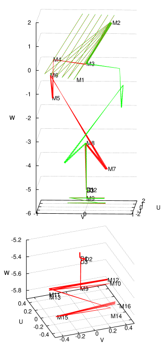
The configuration of the reflecting mirror optics is outlined in Figure 1 Delrez et al. (2001), which traces five rays at various distances to the optical axis starting with the first reflection off the 1.8-m primary M1:
- •
-
•
3 reflections (D1, D2, D3) inside a star rotator Dixon (1979) with incidence angles of 19∘ and two times ;
-
•
and 8 reflections M9 to M16 inside the star separator Delplancke et al. (2004), incidence at M9 close to and otherwise .
After these first 19 reflections, the light beam leaves M16 and heads with a nominal diameter of 80 mm into the light duct. The followup reflections are included taking rough information on the geometries (conic constants and apex positions) with a ruler from a variety of design sketches Wallander et al. (2003); Ferrari et al. (2000); Gitton et al. (2003):
-
•
1 reflection at off what was M12 in the nomenclature before introduction of the star separator Guisard (2003) to align the beam with the axis of the delay line tunnel;
-
•
5 reflections inside the main delay line cat’s eye Hogenhuis et al. (2000); incidence typically ;
-
•
1 reflection at pushing the beam from the delay line tunnel into the VLTI laboratory, into the direction, with the aid of M16 in the old nomenclature Schöller (2007);
-
•
3 reflections below inside the beam compressor, quenching the beam diameter to 18 mm;
- •
-
•
1 dichroic reflection at into the direction; feeding individual instruments.
Numbers in Section III are a snapshot including these 31 reflections, defining the interface towards the first optical element of a generic VLTI instrument.
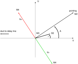
Figure 2 clarifies the azimuth definitions of this manuscript in a projection looking from the zenith above the telescope down the vertical axis onto M3 or M8. The position of the star fixes the angle and zenith angle in local horizontal , , coordinates. The rotator angle (which rotates the image by ) is defined with the same azimuth reference, characterized by the position of D2.
II Ray Tracing
II.1 Reflective Surface Ellipsometry
Given the incidence angles on the mirror surfaces, the polarimetric effects on the beam can be calculated “in principle” (to quote Tinbergen Tinbergen (2007)) if the complex valued refractive index of these are available at the wavelength of interest.
The complex-valued index of refraction for Ag films in the infrared is discussed in the literature Dold and Mecke (1965); Padalka and Shklyarevskii (1961); Schulz (1954b); Schulz and Tangerlini (1954); Schulz (1954a); Bennet et al. (1968); Adams et al. (1975); Hagemann et al. (1975); Ordal et al. (1983), summarized in Fig. 3. Selecting a refractive index out of these is an obvious source of large error in all results shown further down, and the largest uncertainty in modeling efforts of this kind Beck et al. (2005). Early design assumed values Merkle (1986); Burge et al. (1973).
Because no ellipsometric information on any of our reflections is available, we start from a constant for all surfaces, which is the Hagemann–Gudat–Kunz value of Silver interpolated to a wavelength of 2.48 m on logarithmic scales of the real and imaginary part Hagemann et al. (1975). We ignore that M1 is clearly aluminized Ettlinger et al. (1999) and that M9 is a dichroic.

The net effect of this choice is an energy transmission coefficient (absolute value of the determinant of the Jones matrix or the element of the equivalent Mueller matrix) near 0.77.
In a desperate act of tuning this to the anticipated transmission coefficient near 0.2—geometrically scaled by mirror count to a different configuration Puech and Gitton (2005) and removing an estimated contribution from diffuse reflection—, this value of is multiplied by 0.13. The calculations actually use . The average intensity reflection coefficient at the average incidence angle is brought down to .
II.2 Jones Calculus
The ray tracing is started with a minimum distance to the optical axis, as enforced by the M2 diameter. A small corrugation of polarization across the beam as a function of the incidence point on M1 is induced by the variation of incidence angles on the mirror curvatures Breckinridge and Oppenheimer (2004); Patat and Romaniello (2006); Shamir and Chipman (1991). It is not studied here.
The Fresnel coefficients or each reflection are the two entries on the diagonal of each Jones matrix Hurwitz and Jones (1941); Jones (1941, 1942); Pistoni (1995); Elias (2001), in the basis for the two states of polarization. The contribution of an individual reflection is the product with the rotation matrix that adapts the plane of incidence of the previous mirror surface to the plane of incidence at the surface point of the next mirror, and with the free flight propagation term which is a diagonal matrix with two phasors depending on the (optical) path length of the ray from one mirror surface to the next McGuire, Jr. and Chipman (1994); Fymat (1971).
The net effect of the mirror train train is the product of the matrices, four complex values . It converts an initial Jones vector with amplitudes into a vector with amplitudes (Figure 4),
| (1) |

The values plotted in figures 5–7 consider circularly polarized light with
| (2) |
as the input above M1. The relative phase shift is Born (1965). The ellipse main axis is rotated by an angle relative to the main coordinates (where is the horizontal component as we consider the beam in the interferometric laboratory where the planes of incidence are horizontal):
| (3) |
This formula defines as the direction of the longer or of the shorter axis. One can attach it uniquely to the longer axis if the sign of is flipped and shifted by 180∘ for all cases where . This will add 90∘ steps in the followup graphs of wherever the ellipse passes through a “degenerate” circle as a function of pointing direction.
Let the amplitudes of the ellipse in its main coordinates be and (Fig. 4). The amplitude (axis) ratio of the polarization ellipse then is
| (4) |
which is computed from and via Born (1965)
| (5) |
The diattenuation
| (6) |
measures the asymmetry of the ellipse, converted from field amplitudes to energy or flux. (In Figure 4, and therefore .) The value of turns out to be the same for the left- and right-handed circulation of the circular polarization, that is, to be immune against flipping to in the lower component in (2). The value of changes by 90∘ under this reversal of the input polarization.
III Results
III.1 Diattenuation
Figures 5 to 7 show the influence of the pointing direction in the topocentric horizontal system and of the turning angle of the D1–D3 triple on the axis ratio and on the tilt angle of initially circularly polarized star light after its turn into the direction inside the laboratory. Two plots of each figure deal with the N+ configuration, the two other plots with the N- configuration.
In the plots of , the pointing direction is encoded in the circular coordinates of the base: the azimuth is indicated with a blank triangular sector. Pointing to the zenith, –, happens in the middle of the small blank center. Five circular segments, each spanning a zenith interval of 10∘, lead to the outer rim of the plot where the zenith angle reaches 55∘. The value of is plotted as a function over these coordinates and in addition shown on color scales (dark blue for small , light orange for large ) inside the base circle spanned by and . The value of is shown as a scatter plot as a function of for six different zenith angles .
Each of the figures starting with Fig. 5 remains unchanged if one switches between the and the position of the mirrors in the main delay line tunnel (mirrors of the main delay line plus the associated M12 and M16 in the old nomenclature).
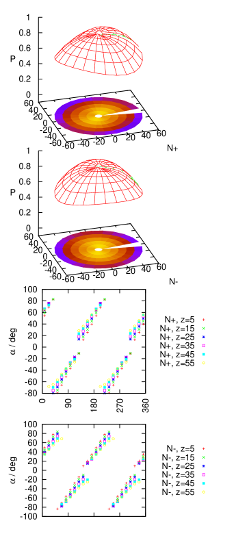
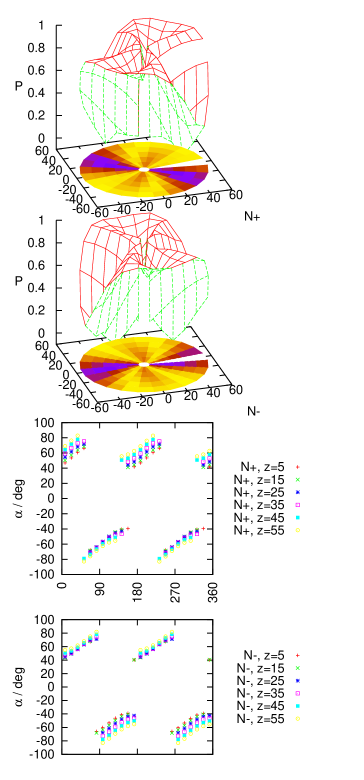
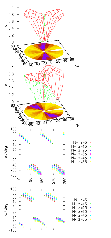
In overview, each of the two constellations N+ or N- of the Nasmyth station has two azimuth directions with preferred, low asymmetry inside the beam, indicated by two blue-shaded radial sections on the base of the 3D plots. These directions co-rotate with the rotator angle , which demonstrates that “in principle” this degree of operational freedom could be used to reduce polarization effects. In practice, the rotator angle will often be deployed to serve other needs, which are not a topic of this manuscript.
In Figure 5, the rotator mirror D2 is aligned with the other mirrors of the Coudé train, and the main observation is that the asymmetry decreases while increasing the zenith angle—an effect of decreasing incidence angles on M3.
The second, main observation is that is large in the other two, unfavorable pointing directions , whereas the dependence on the zenith angle is comparatively weak.
Third, the difference between the and configurations for any prescribed pointing direction is smaller than one might have hoped, although there is some influence on .
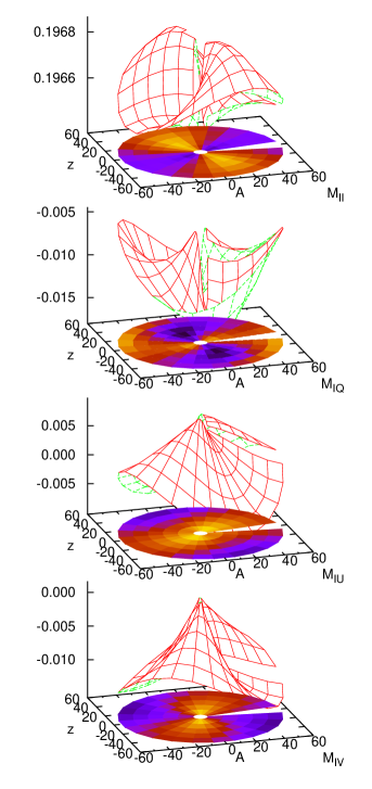
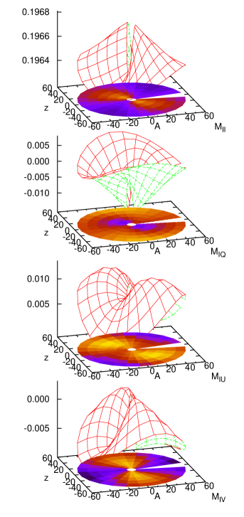
III.2 Mueller Matrix
Another view on the same data is taken by transforming the Jones matrices into Mueller matrices Brosseau et al. (1993); Simon (1987).
Results referring to the and components of the Stokes vector depend on the choice of the coordinate axes of the - and -polarization. Because the mirror train is axially symmetric with respect to reflections off M1 and M2, the -direction above M1 has been defined relative to the plane of incidence on M3, the first mirror to break this symmetry. As we are co-rotating the Nasmyth focus with the azimuth pointing angle , the Cartesian axes of the polarization directions above M1 are therefore defined not a in a coordinate system laid out by the architecture of the duct and main delay line, but in the coordinate system spanned by M2, M3 and M4. The direction of positive is parallel to the direction from M3 to M4 of the N+ configuration. The main intent of this comoving polarization frame in the input pupil is to avoid steps in the definition for azimuth angle transits through some fixed value; as a disadvantage, the representation contains an artificial smooth change of this frame through for one full rotation around the vertical axis.
The components in the interferometric laboratory refer to the natural horizontal coordinate system. (The unfortunate standard names , and of the global coordinate system used in Figs. 1–2 have nothing to do with these assignments of polarization states.)
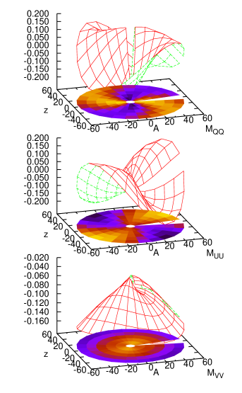
Figure 8 indicates a high survival rate of star light polarization: the three relevant diagonal elements of the Mueller matrix have coupling amplitudes of the order of the intensity transmission of .
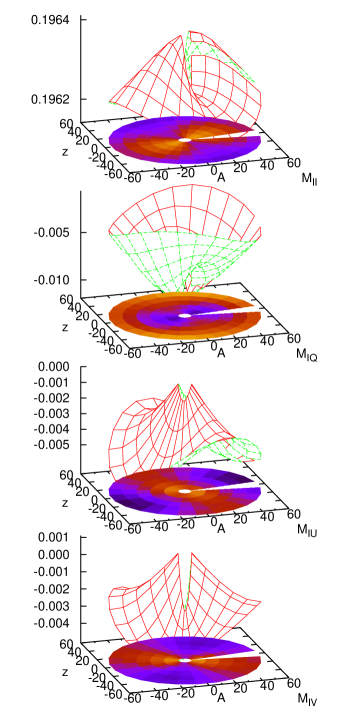
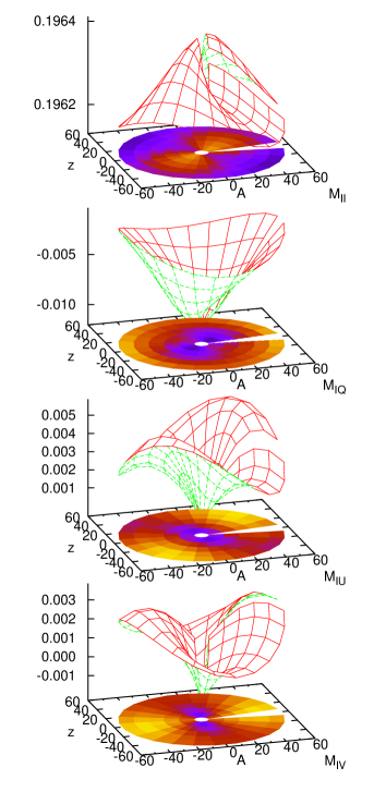
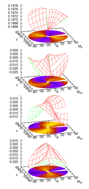
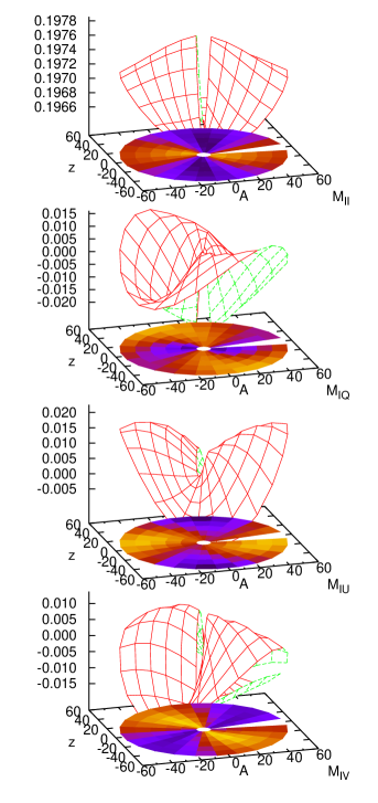
Figures 9–14 illustrate with the top row elements the conversion of the , , and components of the Stokes Vector into an component on exit of the mirror train. These quantities answer the question how far a preferred state of polarization of the beam above M1 induces changes in intensity observed in the interferometric laboratory. Their top graph is , the intensity-to-intensity conversion by the mirror train, which was forced to a value near by the scaling explained in Section II.1. The values of the off-diagonal , and in the other graphs vary typically over a range , which indicates that fully polarized star light may lead to relative intensity variations of up to 10%.
As already apparent in Figs. 5–7, positioning of the rotator in its “neutral” direction leads to the least sensitivity of the matrix elements on the pointing direction: The spread of the -values in Figs. 9–10 is smaller than the spread in Figs. 11–14.
IV Summary
Apparently this is the first publication to assess the VLTI beam polarimetry induced by reflections off the 31 mirrors of a standard optical configuration.
The results remain semi-quantitative because they are based on a blind estimate of the dielectric function of the mirror surfaces, so only the dependence on the variable parts of the mirror train geometry has been emphasized. To first order, interferometry with a symmetric setup, sensitive to differential properties of two telescope beams, is not affected, and the calibration procedure selecting calibrator sources nearby the science target will wipe out most of the pointing dependencies that were outlined here.
For circularly polarized star light, the diattenuation (visibility contrast tested with a rotating analyzer) of the beam is predicted to reach values up to 1.0 for unlucky pointing azimuths, which are themselves a function of the star rotator position.
References
- Adams et al. (1975) Adams, J. R., J. R. Zeidler, and N. M. Bashara, 1975, Opt. Commun. 15(1), 115.
- Beck et al. (2005) Beck, C., R. Schlichenmaier, M. Collados, L. Bellot Rubio, and T. Kentischer, 2005, Astron. Astrophys. 443(3), 1047.
- Bedding et al. (1994) Bedding, T. R., J. M. Beckers, M. Faucherre, N. Hubin, B. Koehler, and O. von der Lühe, 1994, in Very high angular resolution imaging, volume 158 of IAU Symposium, p. 143.
- Bennet and Bennet (1966) Bennet, H. E., and J. M. Bennet, 1966, Optical Properties and Electronic Structure of Metals and Alloys (North Holland, Amsterdam), p. 175.
- Bennet et al. (1968) Bennet, H. E., J. M. Bennet, E. J. Ashley, and R. J. Motyka, 1968, Phys. Rev. 165(3), 755.
- Born (1965) Born, M., 1965, Optik (Springer, Berlin, Heidelberg), 2nd edition.
- Breckinridge and Oppenheimer (2004) Breckinridge, J. B., and B. R. Oppenheimer, 2004, Astrophys. J. 600, 1091.
- Brosseau et al. (1993) Brosseau, C., C. R. Givens, and A. B. Kostinski, 1993, J. Opt. Soc. Am. A 10(10), 2248.
- Burge et al. (1973) Burge, D. K., H. E. Bennett, and E. J. Ashley, 1973, Appl. Opt. 12(1), 42.
- Buscher et al. (2008) Buscher, D. F., F. Baron, and C. A. Haniff, 2008, in Optical and Infrared Interferometry, edited by M. Schöller, W. C. Danchi, and F. Delplancke (Int. Soc. Optical Engineering), volume 7013 of Proc. SPIE, p. 70130E.
- Delplancke (2008) Delplancke, F., 2008, New Astr. Rev. 52(2–5), 199.
- Delplancke et al. (2004) Delplancke, F., J. Nijenhuis, H. de Man, L. Andolfato, R. Treichel, J. Hopman, and F. Derie, 2004, in New Frontiers in Stellar Interferometry, edited by W. A. Traub (Int. Soc. Optical Engineering), volume 5491 of Proc. SPIE, pp. 1528–1535.
- Delrez et al. (2001) Delrez, C., J.-M. Schumacher, C. Flebus, P. Gloesener, and B. Koehler, 2001, in From optical to millimetric interferometry: scientific and technological challenges, edited by J. Surdej, J. P. Swings, D. Caro, and A. Detal, volume 36 of Liège Astrophysics Colloqium, pp. 203–224.
- Dixon (1979) Dixon, R. H., 1979, Appl. Opt. 18(23), 3883.
- Dold and Mecke (1965) Dold, B., and R. Mecke, 1965, Optik 22, 435.
- Elias (2001) Elias, N. M., II, 2001, Astrophys. J. 549(1), 647.
- Ettlinger et al. (1999) Ettlinger, E., P. Giordano, and M. Schneermann, 1999, The Messenger 97, 4.
- Ferrari et al. (2000) Ferrari, M., G. Lemaître, S. Mazzanti, P. Lanzoni, F. Derie, P. Gitton, and S. Ménardi, 2000, in Interferometry in Optical Astronomy, edited by P. J. Lena and A. Quirrenbach (Int. Soc. Optical Engineering), volume 4006 of Proc. SPIE, pp. 104–115.
- Fymat (1971) Fymat, A. L., 1971, Appl. Opt. 10(12), 2711.
- Gitton et al. (2003) Gitton, P., M. Cantzler, B. Koehler, and P. Kervella, 2003, in Interferometry for Optical Astronomy II, edited by W. A. Traub (Int. Soc. Optical Engineering), volume 4838 of Proc. SPIE, pp. 1182–1192.
- Guisard (2003) Guisard, S., 2003, in Interferometry for Optical Astronomy II, edited by W. A. Traub (Int. Soc. Optical Engineering), volume 4838 of Proc. SPIE, pp. 1256–1263.
- Hagemann et al. (1975) Hagemann, H.-J., W. Gudat, and C. Kunz, 1975, J. Opt. Soc. Am. 65(6), 742.
- Hogenhuis et al. (2000) Hogenhuis, H., M. Visser, G. Ruwiel, F. Hommes, A. Wielders, and A. Couwenberg, 2000, in Interferometry in Optical Astronomy, edited by P. J. Lena and A. Quirrenbach (Int. Soc. Optical Engineering), volume 4006 of Proc. SPIE, pp. 198–206.
- Hurwitz and Jones (1941) Hurwitz, H., and R. C. Jones, 1941, J. Opt. Soc. Am. 31(7), 493, the in (18b) should read .
- Johnson and Christy (1972) Johnson, P. B., and R. W. Christy, 1972, Phys. Rev. B 6(12), 4370.
- Jones (1941) Jones, R. C., 1941, J. Opt. Soc. Am. 31(7), 488.
- Jones (1942) Jones, R. C., 1942, J. Opt. Soc. Am. 32(8), 486, the upper left element of in (8) should read , not .
- Launhardt et al. (2005) Launhardt, R., T. Henning, D. Queloz, A. Quirrenbach, E. Bakker, H. Baumeister, P. Bizenberger, H. Bleuler, F. Delplancke, F. Derie, M. Fleury, A. Glindemann, et al., 2005, in Astrometry in the age of the next generation of large telescopes, edited by P. K. Seidelmann and A. K. B. Monet (Astron. Soc. Pacific), volume CS-338 of ASP Conf. Ser., pp. 167–175.
- McGuire, Jr. and Chipman (1994) McGuire, Jr., J. P., and R. A. Chipman, 1994, Appl. Opt. 33(22), 5080.
- Merkle (1986) Merkle, F., 1986, in Second workshop on ESO’s Very Large Telescope, edited by S. D’Odorico and J.-P. Swings (ESO), volume 24 of ESO Conference and Workshop Proceedings, pp. 403–416.
- Ordal et al. (1983) Ordal, M. A., L. L. Long, R. J. Bell, S. E. Bell, R. R. Bell, R. W. Alexander, Jr, and C. A. Ward, 1983, Appl. Opt. 22(7), 1099.
- Padalka and Shklyarevskii (1961) Padalka, V. G., and I. N. Shklyarevskii, 1961, Opt. Spectr. 11(4), 285.
- Patat and Romaniello (2006) Patat, F., and M. Romaniello, 2006, Publ. Astron. Soc. Pac. 118(839), 146.
- Pepe et al. (2008) Pepe, F., D. Queloz, T. Henning, A. Quirrenbach, F. Delplancke, L. Andolfato, H. Baumeister, P. Bizenberger, H. Bleuler, B. Chazelas, F. Dérie, L. Di Lieto, et al., 2008, in Optical and Infrared Interferometry, edited by M. Schöller, W. C. Danchi, and F. Delplancke (Int. Soc. Optical Engineering), volume 7013 of Proc. SPIE, p. 70134P.
- Pistoni (1995) Pistoni, N. C., 1995, Appl. Opt. 34(34), 7870.
- Puech and Gitton (2005) Puech, F., and P. Gitton, 2005, Interface Control Document between VLTI and its Instruments, VLT-ICD-ESO-15000-1826. On page 110, should read , should read , and should read .
- Sahlmann et al. (2009) Sahlmann, J., S. Ménardi, R. Abuter, M. Accardo, S. Mottini, and F. Delplancke, 2009, Astron. Astrophys. 507(3), 1739.
- Schöller (2007) Schöller, M., 2007, New Astronomy Reviews 51(8–9), 628.
- Schulz (1954a) Schulz, L. G., 1954a, J. Opt. Soc. A 44(7), 540.
- Schulz (1954b) Schulz, L. G., 1954b, J. Opt. Soc. Am. 44(5), 357.
- Schulz and Tangerlini (1954) Schulz, L. G., and F. R. Tangerlini, 1954, J. Opt. Soc. A 44(5), 362.
- Shamir and Chipman (1991) Shamir, J., and R. A. Chipman, 1991, J. Mod. Opt. 38(2), 327.
- Simon (1987) Simon, R., 1987, J. Mod. Opt. 34(4), 569.
- Tinbergen (2007) Tinbergen, J., 2007, Publ. Astron. Soc. Pac. 119(862), 1371.
- Wallander et al. (2003) Wallander, A., J. Argomedo, P. Ballester, B. Bauvir, M. Comin, R. Donaldson, P. Duhoux, A. Gennai, B. Gilli, N. Housen, A. Huxley, R. Karban, et al., 2003, in Astronomical Telescopes and Instrumentation 2002 (Int. Soc. Optical Engineering), volume 4848 of Proc. SPIE, no. 11.
- Witzel et al. (2011) Witzel, G., A. Eckart, R. M. Buchholz, M. Zamaninasab, R. Lenzen, R. Schödel, C. Araujo, N. Sabha, M. Bremer, V. Karas, C. Straubmeier, and K. Muzic, 2011, Astron. Astrophys. 525, A130.