Silicon photomultiplier timing performance study
Abstract
Many characteristics of Silicon Photomultipliers can be tuned with temperature and operation voltage. We present preliminary results of a study of the effect of these two operation parameters on the time resolution of large active area Multi-Pixel Photon Counters (MPPCs) manufactured by Hamamatsu. Measurements at ∘C, ∘C, and ∘C at different bias voltages were performed. The time resolution is best at low temperature and high over-voltage. Most significant improvements can be achieved in cases with low number of fired pixels (10 pixels). Between the worst and best case among the considered conditions a factor of 5 improvement was observed. In cases with large number of fired pixels (40 pixels) the effect of temperature and operation voltage becomes smaller. The timing performance still improves with decreasing temperature ( factor of 2) but it hardly depends on the operation voltage. The study shows, that especially in applications where only few photons are available for detection a careful optimization of temperature and operation voltage are advisable to obtain optimum timing results with the MPPC.
keywords:
Silicon photomultiplier, Cherenkov detector, time resolution1 Introduction
SiPMs have numerous advantages as compared to other photo detectors. The low operation voltage, high gain, fast timing, compactness, and moreover the insensitivity to magnetic fields make them excellent candidates for different applications [1, 2, 3]. In many applications in experimental physics time information is gained from light detecting devices. In subatomic physics e.g. time-of-flight (TOF) measurements, using scintillation counters in combination with light sensitive devices is a widely used technique to determine the velocity of a particle and in combination with other detectors to perform particle identification (PID). The performance of such detector systems crucially depends on the time resolution of the photo sensor used. In PID a better time resolution of the photo sensor allows better particle separation. The operation characteristics of SiPM depends mainly on two parameters - the operation voltage and temperature. In view of possible usage of SiPMs in timing applications we investigate its timing performance as function of these two parameters.
For the current study we focus on the recent large active area SiPMs - the Multi-Pixel Photon Counters (MPPCs) from Hamamatsu. These MPPC photo sensors are sensitive in the blue-light range ( nm) which matches well with the light emitted by scintillators and Cherenkov radiators. The devices of the series S10362-33-100C [4] which we are investigating, have a sensitive area of 33 mm2. They consist of 900 APDs of 100100 with a total fill factor of about 78.5%. Their nominal gain is and they have a terminal capacitance of 320 pF. The photon detection efficiency in the blue light range depends on temperature and operation voltage and is typically % . According to Hamamatsu the time resolution at ∘C, nominal operation voltage, and single photon level is ps. Measurements of dark current, dark count rate and cross-talk of this device have been presented elsewhere [6, 5].
2 Measurement setup
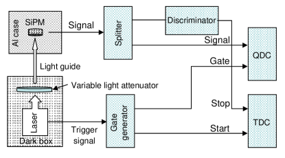
The setup used to study the timing performance of the MPPC device is sketched in figure 1.
To illuminate the SiPM with blue laser light, we use a picosecond blue laser system from Advanced Laser Diode Systems (PIL063SM) [7] equipped with a 408 nm head with a pulse width of ps. The light intensity on the SiPM is controlled by the tunable laser power and an attenuation filter. The repetition rate can be regulated from single shot to 1 MHz. The attenuated light was delivered to the SiPM by an optical fiber of 1 mm diameter.
The SiPM housing is mounted in a light and vacuum tight aluminum box. The SiPMs are thermally coupled to water-cooled peltier elements, which allows to regulate the temperature of the photo sensor from room temperature down to approximately ∘C with ∘C of accuracy. In order to avoid condensation, the aluminum box is evacuated to a pressure of mbar. The SiPM signal is amplified with a fast preamplifier (AMP_0611) from Photonique SA [8]. In order to minimize the electronic noise pick-up the SiPMs are attached directly to the preamplifier board.
The readout electronics is set up to measure charge distributions and time distributions, simultaneously. The signal output from the SiPM is split into two lines. One is connected to a charge-to-digital converter (QDC, LeCroy ADC-2249W, pC/ch) for the charge measurements. The other line is fed into a leading edge discriminator and the output of the discriminator is fed into a time-to-digital converter (TDC, Phillips TDC-7186, ps/ch) for time measurements (stop signal). The data acquisition is triggered by the trigger-out signal of the laser. It is used as start for the TDC and also to generate a sampling gate for the QDC.
The QDC and TDC signals were recorded by a personal computer via Wiener CAMAC-CC32 PCI bus interface and stored for offline analysis.
3 Measurements and results
With this series of measurements we aim at investigating the temperature and bias voltage dependence of the timing performance of the MPPC. Therefore we determined the time resolution at three different temperatures ( ∘C, ∘C, ∘C) and several bias voltages as function of the number of fired pixels. The measurement were performed at totally 13 pairs of temperature/bias voltage values.
The input light intensity to the MPPC was adjusted at the beginning of the measurement series and was kept constant for all measurements. The pulse frequency was set to kHz.
Instead of presenting the data as function of bias voltage we use the over-voltage as parameter. The over-voltage is defined as the difference between the applied bias voltage and the breakdown voltage, which is a function of temperature. The breakdown voltage was determined as described in [9]. For the specific example of measured MPPC the breakdown voltage is V at ∘C, V at ∘C, V at ∘C.
For each pair of temperature and bias voltage the measurement procedure was as follows.
-
1.
Determine gain and conversion factor between QDC value and number of fired pixels.
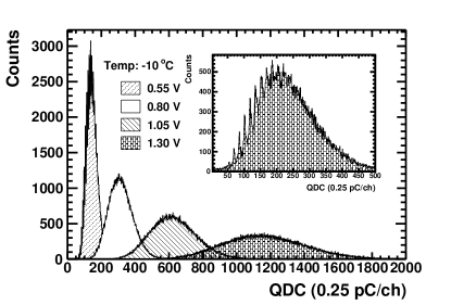
Both quantities can be determined from the analysis of separated peaks in the charge distribution corresponding to different values of fired pixels. An example of such a distribution is displayed in the inset of figure 2. QDC value and number of fired pixels (NFP) are related by
(1) where is the position of the peak corresponding to fired pixel and . The gain G is given by
(2) where the charge of an electron is C and the gain of the preamplifier .
In most cases to be able to see separate single photon peaks in the charge distribution the light intensity needed to be attenuated. For the timing measurement, however, the light intensity was reset to the nominal value. E.g. the most right charge distribution in figure 2 and the distribution in the inset of figure 2 have been taken at the same temperature and over-voltage but at different light intensities. Whereas the first, taken at nominal light intensity, is used for timing measurements the later is used to determine the gain at the given operation conditions.
-
2.
Select in QDC spectrum narrow ranges corresponding to a given number of fired pixels.
The charge distributions measured at nominal light intensity are broad as shown in figure 2. In order to determine the time resolution as function of NFP we select narrow ranges of the charge distributions which can be associated with a given number of fired pixels through relation (1).
With this procedure the time resolution dependence on the NFP is obtained by selecting successive narrow portions (corresponding to 1 or 2 fired pixels in width) of a broad distribution of NFP and not by tuning the input light intensity. The range of NFP which can be grasped with this method is limited and different for each SiPM operation condition. This is because the charge distributions only cover a portion of the full QDC range, which depends on the SiPM operation condition (see figure 2). In order to gain access to a broader range of NFP, the light intensity needed to be changed. This we explicitly excluded for this study not to bias the results by a possible influence on the incident light intensity.
-
3.
Apply slew correction and fit the resulting TDC distributions with a Gaussian function.
Since we are using a leading edge discriminator in the timing channel a slew correction is applied to correct for the signal height dependence of the stop signal. The slew correction parameters are determined with all data points. The corrected TDC distribution of each NFP-bin is fitted with a Gaussian function. The time resolution is defined to be the sigma of the fitted width. Since the NFP-bins are narrow the slew correction has only a small effect on the time resolution of an individual bin.
Changing and stabilizing the temperature of the system takes much longer than changing the bias voltage. Therefore we first performed the measurements at fixed temperature and different bias voltages and then stepped in temperature.
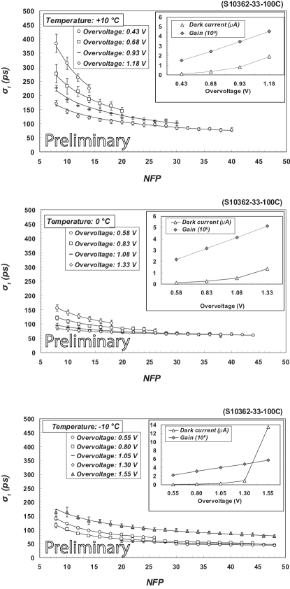
The results of these measurements are summarized in figure 3. The panels show results for ∘C (upper panel), ∘C (middle panel), and ∘C (lower panel). The time resolution is plotted as NFP for different values of over-voltage. In the insets the gain and dark current are displayed as function of over-voltage.
The contribution from the data acquisition electronics to the time resolution was measured by feeding a constant-amplitude test-pulse into the system. The contribution of the electronics measured in this way (excluding contributions from the preamplifier) is 20 ps.
4 Discussion and summary
The measurements of the time resolution of the MPPC at different temperatures and over-voltages presented in the previous section reveal three general trends - 1. the time resolution improves with increasing NFP, 2. within the covered temperature range of ∘C and ∘C the time resolution improves with decreasing temperature, and 3. the time resolution improves with increasing over-voltage (except for extreme cases which are discussed below).
In order to guide the eye the curves at given temperature and over-voltage are fitted with the function . The results are shown as bold lines in figure 3. At first view the function seems to fit well the data. However, closer inspection reveals deviations of the data points at low NFP from this relation. This needs further investigation.
Temperature and over-voltage dependence of are most prominent at small NFP. Whereas at fired pixels the range of values measured at the selected conditions is from to ps (factor 5) the range at fired pixels is much smaller (only from to ps, factor 2). The temperature dependence is not linear. The improvement of which is achieved by decreasing the temperature from ∘C to ∘C is considerably larger than the improvement achieved by lowering the temperature by additional ∘C to ∘C. How much the time resolution can be improved by choosing the appropriate temperature also depends on the over-voltage applied to the MPPC. The influence of the temperature is large when the MPPC is operated with a low over-voltage. With increasing over-voltage the importance of the temperature decreases.
Although operating the MPPC at large over-voltage has a positive effect on the timing performance this general rule breaks down when the bias voltage is substantially riced above the recommanded operation range. Then the dark current starts to steeply increase and a deterioration of the time resolution is observed. An example of this behavior can be observed in the ∘C-data at an over-voltage of V (lower panel of figure 3). A similar behaviour is also observed in other types of MPPCs (see e.g. figure 4 in [10]). Operating the MPPC at large over-voltage is accompanied by an increase of the dark current and dark counts (see insets in figure 3). This can be a severe drawback in applications where only few photons are available for detection.
To obtain best performance of the MPPC for a given application a careful optimization of the operation conditions is obviously required. To optimize timing performance and also to achieve low dark count rates, control of the temperature is most important. Especially in applications with low light intensities (e.g. Cerenkov counters) the timing performance can be significantly improved by operating the device at low temperatures. Our current measurements reach down to ∘C. A further improvement of the timing performance can be expected at even lower temperatures [11]. Using high over-voltage can also improve the time resolution. This is however accompanied with an increase of the dark counts. Attention must be paid not to operate the MPPC at an over-voltage above the value at which the dark current starts to rapidly increase and the timing performance starts to degrade. An optimum operation voltage seems to be slightly below this reversal point. However, since the over-voltage corresponding to the reversal point strongly depends on the temperature (see e.g. figure 1 in [3]) operation at this point requires stable temperature control.
5 Acknowledgments
This work is partly supported by INTAS (project 05-1000008-8114) and Hadronphysics2 (project 227431). One of us (G.A.) acknowledges the support by the Egyptian Ministry of higher education.
References
- [1] P. Buzhan et al., Nucl. Instr. and Meth. A 504 (2003) 48.
- [2] K. Suzuki et al., Nucl. Instr. and Meth. A 610 (2009) 75.
- [3] G.S.M. Ahmed et al., Nucl. Instr. and Meth. A (in press)
- [4] http://jp.hamamatsu.com/products/sensor-ssd/4010/index_en.htmli.
- [5] G.S.M. Ahmed et al., J.Inst. 4 (2009) P09004.
- [6] D. Renker, Nucl. Instr. and Meth. A 567 (2006) 48.
- [7] Advanced Laser Diode Systems, http://www.alsgmbh.com/
- [8] Photonique SA, Switzerland (http://www.photonique.ch).
- [9] R. Vinke et al., Nucl. Instr. and Meth. A 610 (2009) 188.
- [10] A. Ronzhin et al., Nucl. Instr. and Meth. A 616 (2010) 38-44.
- [11] G. Collazuol et al., Nucl. Instr. and Meth. A (in press).