Surface alignment and anchoring transitions in nematic lyotropic chromonic liquid crystal.
Abstract
The surface alignment of lyotropic chromonic liquid crystals (LCLCs) can be not only planar (tangential) but also homeotropic, with self-assembled aggregates perpendicular to the substrate, as demonstrated by mapping optical retardation and by three-dimensional imaging of the director field. With time, the homeotropic nematic undergoes a transition into a tangential state. The anchoring transition is discontinuous and can be described by a double-well anchoring potential with two minima corresponding to tangential and homeotropic orientation.
pacs:
61.30.-v ; 42.65.-k ; 42.70.DfSpatial bounding of a liquid crystal (LC) lifts degeneracy of molecular orientation specified by the director and sets an ”easy axis” at the surface. Deviation of from requires some work thus establishing a phenomenon of ”surface anchoring” that has been explored extensively for thermotropic LCs Horn ; Cognard ; YangRosenblatt ; Volovik ; Barbero ; YokoyamaVan ; Sluckin ; Bechhoefer ; Book ; Patel ; Sheng . For lyotropic LCs, such as water solutions of polyelectrolytes, surfactants, dyes, etc., the studies of anchoring are scarce. The view is that the surface alignment of lyotropic LCs is determined by an excluded volume effect, which favors the longest dimension of building units to be parallel to a substrate Meyer ; Poniewierski ; Sharlow ; Poulin . We study surface phenomena in nematic lyotropic chromonic LCs (LCLCs), a distinct class of self-assembled LCs formed by water solutions of plank-like molecules with polyaromatic cores and ionic peripheral groups Lydon . Reversible chromonic assembly and mesomorphism are displayed broadly by dyes, drugs and nucleotides Lydon . In water, the LCLC molecules stack face-to-face, forming elongated aggregates. The aggregates are not fixed by covalent bonds, being polydisperse with an average length that depends on temperature , volume fraction , and stacking energy Dickinson . We demonstrate that in LCLCs, can be either parallel to a substrate (planar or tangential alignment, denoted ”P”) or perpendicular (homeotropic, or H alignment), with discontinuous transitions between the two, thus suggesting that both entropy and anisotropic molecular interactions control the surface phenomena.
We study disodium cromoglycate (DSCG) Lydon , (Spectrum Inc, purity ), dissolved in water at 15 wt % (mixture A) and 12.5wt% doped with 1.5wt% of Na2SO4 (mixture B). The H alignment was achieved by treating glass plates with 1% water solution of N,N-dimethyl-N-octadecyl-3-aminopropyl trimethoxysilyl chloride (DMOAP) Cognard . The two plates are separated by Mylar strips; the cell thickness was measured by light interference technique. The cells were filled at K, sealed with a UV-cured Norland epoxy glue, and cooled down to K with a rate K in a thermal stage HS-1 (Instec, Inc.). We used an LC PolScope for in-plane mapping of optical retardation , where , is the angle between and the normal to the cell, and are the ordinary and extraordinary refractive indices, respectively. At 546 nm and K, we determined and for A and for B Nastishin . To image , we used fluorescence confocal polarizing microscopy (FCPM), by doping the LCLC with 0.003 wt.% of fluorescent acridine orange (AO, Sigma-Aldrich) and probing it with a focused laser beam Pramana . The fluorescence intensity depends on the angle between and polarization of light, being maximum for and minimum for , suggesting that AO intercalates between the DSCG molecules.
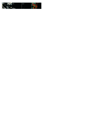
The initial unaligned texture coarsens and then shows dark expanding nuclei of the H state that fill the entire cell, Fig.1. The H alignment is stable as verified by applying a strong magnetic field, up to 7 kG, to tilt . Once the field is switched off, the H orientation is restored. After a certain time 10-20 hours, the LCLC undergoes an H-P transition through nucleation and expansion of birefringent domains, Fig.1c,d. These appear not only at the periphery but also in the middle of samples, Fig.1c. Two similar cells, one left under normal conditions and another one immersed in a mineral oil, demonstrated similar evolution. Therefore, a possible slow drying is not a major contributor to the effect, although the dynamics of aggregate assembly most certainly is. The H-P transition might be direct, with abruptly changing from 0 to , line 1, or indirect, with an intermediate step , lines 2, 3 in Fig.2a. The tilt at the states’ boundaries varies broadly, from 100 nm/m, to 1 nm/m. FCPM of the vertical cross sections shows that the boundaries represent sharp walls that are either vertical (large ) or tilted (small ). For example, Fig.2b shows a tilted () boundary separating an H layer with and a P layer with ; at either of the two H plates, the transition from to is abrupt.

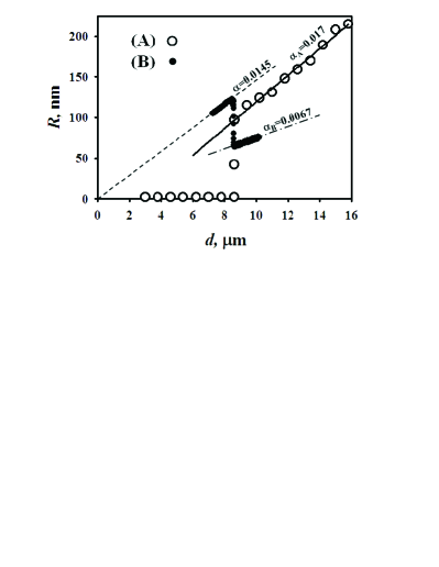
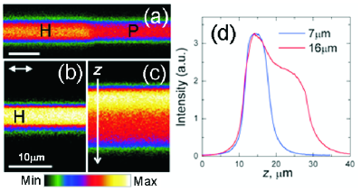
To quantify the surface properties further, we use hybrid aligned wedge cells Barbero , assembled from two different plates, an H plate with DMOAP and a P plate with buffed polyimide SE-7511 (Nissan). The dihedral angle is small, . The cells show a critical thickness at which changes abruptly, Fig.3; varies in the range 5-10 m from sample to sample. At , is uniform, either in the H state, if the experiment is performed at the beginning of for the mixture A, or in the P state for the mixture B. At , is distorted, as evidenced by the tilt that is neither 0 nor , Fig.3. The behavior of is complex and depends on the tilt of walls separating the states and . The walls can be vertical, Fig.4a, tilted (as in Fig.2b), or practically horizontal, Fig.4c. We compare the cross sections of thin and thick parts of the same wedge, Fig.4b,c,d. The thin part is in a uniform H state, with fluorescence equally strong for any in-plane orientation of , Fig.4b. In the thick part, Fig.4c, the top 1/3 is occupied with an H layer, as evidenced in Fig.4d by an overlap of the fluorescence profiles. In the bottom 2/3, is close to planar, as the fluorescence is weak, Fig.4c,d.
The experiments suggest that in the studied LCLC, can be either tangential (planar) or homeotropic. The H alignment is stable only within a finite period of time . The anchoring transitions are strongly discontinuous. The findings are unusual, as lyotropic LCs are notoriously hard to align and when they do align, there are no anchoring transitions. The H-P transitions occur in thermotropic LCs, but they are continuous there Volovik ; Patel . Discontinuous transitions were reported for in-plane realignment at anisotropic crystalline substrates Horn ; Bechhoefer and for patterned plates with spatially varying easy axis Sheng . As shown by Sluckin and Poniewierski Sluckin , the simplest potential leading to the first-order H-P transitions in semi-infinite samples is . This form also describes well the reorientation of thermotropic LCs by external fields YangRosenblatt ; YokoyamaVan . For the H plate with , can be cast as with the anchoring coefficients and . The change from to corresponds to the first-order H-P transition that has not been observed so far experimentally Book . Sluckin and Poniewierski Sluckin expressed and through the temperature-dependent scalar order parameter so that the transitions were temperature-driven. In our case, the changes in and can be related also to the dynamics of self-assembly. Since the H state is observed after the samples are cooled down from the isotropic phase, it should be accompanied by the growth of aggregates, as . Short and long aggregates might align differently at the substrates, say, normally and tangentially, the entropy effect being one of the reasons.
For cells of a finite , such as the hybrid aligned wedges, the free energy per unit area should include both anchoring and elastic terms:
| (1) |
where , and are the splay and bend elastic constants; and , to guarantee at the P plate. For , the conflicting boundary conditions are satisfied by reorienting by . As decreases, the elastic torque , determined by the actual polar angles and at the plates, becomes stronger, forcing and to deviate from their ”easy” values and . At some , the plate with weaker anchoring might give up, allowing to be uniform. For analytical treatment, we assume and fix at the stronger anchored plate, as supported by FCPM, Fig.2b, 4.
For the case A in Fig.3, , thus . The values of that minimize are found from the conditions and . When and , has an absolute minimum at and a local one at . The two are separated by a barrier at . For a finite , with preserves its double-well features. In particular, is still a local minimum. The coordinate of the absolute minimum, however, becomes smaller than , because of the elastic torque . We evaluate near to find . The difference vanishes at . For , the uniform H state is stable, while for , the hybrid state has the lowest energy. The transition is discontinuous, with a big jump in the range that corresponds to the limits . Similarly for the case B, and . At smaller than , the uniform P state is stable, and at , the hybrid state with is stable. The transition is discontinuous, with the jump in the range (1.31-1.57). The qualitative features of this analytical description remain intact when the full form of in Eq.(1) is analyzed numerically.
The model above explains why the thin parts of wedge cells are uniform and why the director orientation at the surfaces is close to 0 and . The thickness has the meaning of surface extrapolation length, also called the de Gennes-Kleman length. The value m is of the same order as the one extracted from the experiments on elastic distortions around colloidal inclusions in LCLCs Shiyan . With pN Nastishin_ELC , one estimates J/m2, which is comparable to the anchoring coefficients found in thermotropic LCs in the regime of ”weak” anchoring Cognard . The small facilitates metastable surface orientations, analogs of the strongly supercooled states. Their transformations into the stable states are hindered by the barriers featured by and , and by the surface defects of line tension that separate the areas with a different director tilt. These defects are seen as cusps in , Fig.2a. The nuclei of new alignment should be of a size or larger, to overcome the nucleation barrier . The maximum is. With J/m2, the nucleation barrier is large, J , which signals that the metastable states can be long-lived and that nucleation is heterogeneous, assisted by inhomogeneities, Fig.1.
The general expression matches the data in Fig.3 at , with =0 in the H state and in the P case. For the deformed states at , the standard model is that is determined by smooth variations of with Barbero . Then for the A case, , while for the B case, , where , Barbero . For , using the smallness of , one finds and . Using the discontinuities of in Fig.3, 97 nm for A and 64 nm for B, we conclude that the jumps in and at are substantial, 1.3-, as expected from the model above. The tilts are much harder to describe as these are affected by the tilt of boundaries between different states. Assuming a vertical boundary for the cell B and the expression for above, one finds that at , or larger. The experimental is by 10% smaller, Fig.3. The difference can be accounted for by the fact that . Numerical evaluation of with shows that corresponds to , a reasonable result Nastishin_ELC . The discrepancy between the theoretical 0.01 and the experimental 0.017 is more significant. It cannot be explained by . To show this, we assumed (to maximize the theoretical ) and then evaluated for 1. By changing the ratio in the range to , we find changing from 0.007 to 0.013, still smaller than the experimental value. In principle, 0.017 can be obtained by allowing a nonzero . However, with , the cell retardation should be much higher than in the experiment, e.g., one should measure 140 nm at m, and the actual result is only 100 nm, Fig.3. We thus conclude that at is affected by the tilted sharp boundaries such as the ones in Fig.2b and Fig.4c,d. The boundaries with sharply varying imply a changing . The latter is expected to happen through the ”interchanging eigenvalues” of the tensor order parameter in thin hybrid aligned cells Palffy with , where is the biaxial correlation length. In thermotropic nematics, nm Palffy , but in LCLCs, can be larger, since the gradients of can be accommodated by redistribution of short and long aggregates in the intrinsically polydisperse LCLC. The standard approach to calculate and is not applicable to the case with a changing .
To conclude, we demonstrated that in the LCLC, surface alignment can be both planar and homeotropic with a strongly discontinuous transition between the two that can be described by a double-well anchoring potential. Much more work is needed to gain an understanding of LCLC behavior at the surfaces and in the bulk, as the study suggests that the LCLC structure is affected by kinetics of self-assembly and that the director distortions can be accompanied by gradients of the scalar order parameter.
We are grateful to the anonymous referees for useful suggestions. The work was supported by NSF Materials World Network on Lyotropic Chromonic Liquid Crystals DMR076290, ARRA DMR 0906751, Ohio Research Cluster on Surfaces in Advanced Materials, NAS of Ukraine Grant #1.4.1B/109, Fundamental Research State Fund Project UU24/018, and by the Ministry of Education and Science of Ukraine, Project 0109U001062.
References
- (1) R.G. Horn, J.N. Israelachvili, E. Perez, J. Physique 42, 39 (1981).
- (2) J. Cognard, Mol. Cryst. Liq. Cryst., 78, Suppl. 1, 1 (1982).
- (3) K.H. Yang, C. Rosenblatt, Appl. Phys. Lett. 43, 62 (1983).
- (4) G.E. Volovik, O.D. Lavrentovich, Zh. Eksp. Teor. Fiz. 85, 1997 (1983) [Sov. Phys. JETP 58, 1159 (1983)].
- (5) G. Barbero, N.V. Madhusudana, J.F. Palierne, G. Durand, Phys. Lett. 103A, 385 (1984).
- (6) H. Yokoyama, H.A. van Sprang, J. Appl. Phys. 57, 4520 (1985).
- (7) T.J. Sluckin, A. Poniewierski, in Fluid Interfacial Phenomena, ed. C.A. Croxton (John Wiley and Sons, 1986).
- (8) J. Bechhoefer, J.-L. Duvail, L. Masson, B. Jérôme, R.M. Hornreich, P. Pieranski, Phys. Rev. Lett. 64, 1911 (1990).
- (9) S. Faetti, in Physics of Liquid Crystalline Materials, ed. I.-C. Khoo and F. Simoni (Gordon and Breach, 1991).
- (10) J.S. Patel, H. Yokoyama, Nature 362, 525 (1993).
- (11) B. Zhang, F.K. Lee, O.K.C. Tsui, P. Sheng, Phys. Rev. Lett. 91, 215501 (2003).
- (12) R. B. Meyer, in Polymer Liquid Crystals, ed. A. Ciferri, W. R. Krigbaum, and R. B. Meyer (New York, Academic Press, 1982).
- (13) A. Poniewierski, R. Hołyst, Phys. Rev. A38, 3721 (1988).
- (14) M.F. Sharlow, W.M. Gelbart, Liquid Cryst. 11, 25-30 (1992).
- (15) P.Poulin, N. Frances, O. Mondain-Monval, Phys. Rev. E59, 4384 (1999).
- (16) J. Lydon, Current Opin. Coll. Int. Sci. 8, 480 (2004).
- (17) A.J. Dickinson, N.D. LaRacuente, C.B. McKitterick, P.J. Collings, Mol. Cryst. Liq. Cryst. 509, 9 (2009).
- (18) Yu. A. Nastishin, H. Liu, T. Schneider, V. Nazarenko, R. Vasyuta, S.V. Shiyanovskii and O.D. Lavrentovich, Phys. Rev. E72, 041711 (2005).
- (19) O.D. Lavrentovich, Pramana-J. Phys. 61, 377 (2003).
- (20) Yu.A. Nastishin, K. Neupane, A.R. Baldwin, O.D. Lavrentovich, S. Sprunt. Electronic Liquid Crystal Communications. July 15, 2008, p.1-4.
- (21) S. V. Shiyanovskii, T. Schneider, I. I. Smalyukh, T. Ishikawa, G. D. Niehaus, K. J. Doane, C. J. Woolverton, and O. D. Lavrentovich, Phys. Rev. E71, 020702(R) (2005).
- (22) P. Palffy-Muhoray, E.C. Gartland, J.R. Kelly, Liquid Crystals, 16, 713-718 (1994); H.G. Galabova, N. Kothekar, D.W. Allender, Liquid Crystals, 23, 803 (1997); A. Šarlah, S. Žumer, Phys. Rev. E60, 1821 (1999); C. Chiccoli, P. Pasini, A. Šarlah, C. Zannoni, S. Žumer, Phys. Rev. E67, 050703(R) (2003); P.I.C. Teixeira, F. Barmes, C. Anquetil-Deck, D.J. Cleaver, Phys. Rev. E79, 011709 (2009); D. de las Heras, L. Mederos, E. Velasco, Phys. Rev. E79, 011712 (2009).