Simulation of Beam-Beam Background at CLIC
Abstract
The dense beams used at CLIC to achieve a high luminosity will cause a large amount of background particles through beam-beam interactions. Generator level studies with GuineaPig and full detector simulation studies with an ILD based CLIC detector have been performed to evaluate the amount of beam-beam background hitting the vertex detector.
1 Introduction
The Compact Linear Collider (CLIC) is designed for electron-positron collisions at c.m. energies up to 3 TeV [1]. The normal-conducting RF cavities operate at a gradient of 100 MV/m, and the RF power is distributed along the accelerator by a 2.4 GeV, high intensity ”drive beam”. In order to achieve the desired luminosity, CLIC operates with bunch trains of 312 bunches separated by 0.5 ns, with a repetition rate of 50 Hz and transverse bunch size of and a length of . A number of design considerations have led to a crossing angle at the interaction point of 20 mrad. The large number of electron-positron pairs produced by the beam-beam interaction has to be studied in a full detector simulation to evaluate and minimize the impact on the detector performance.
2 Detector simulation and forward region
The detector used for the simulation is based on the ILD detector concept [2] for the ILC. A few modifications are needed to adapt the detector for CLIC: Most importantly, a 4 Tesla solenoid field without Anti-DID is used, because the Anti-DID reduces the luminosity at CLIC by about 20% [3]. The vertex detector (VXD) consists of three double layers, each with a total length of 25 cm and a radius of 31, 46 and 60 mm. The inner most layer is placed at twice the radius compared to the VXD of the ILC-ILD.
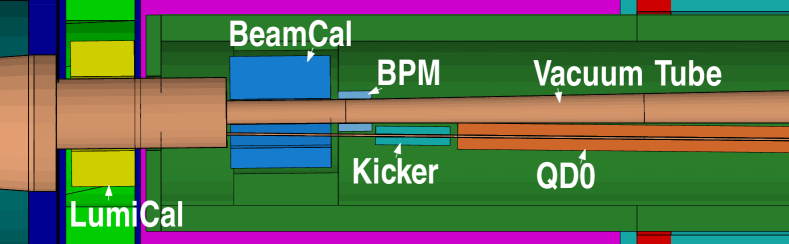
The forward region of a detector at CLIC (Figure 1) has to provide the same functionality as for a detector at the ILC. The goal is to keep the number of particles back-scattering into the central detectors as small as possible while still maintaining an angular coverage down to polar angles of a few millirad if possible. The CLIC forward region therefore contains most of the elements that are planned for the ILC: A Luminosity Calorimeter (LumiCal) to precisely count the number of Bhabha events in an angular region between about 40 and 100 mrad to measure the luminosity; a Beam Calorimeter (BeamCal), extending the angular coverage of the forward calorimeters down to polar angles of about 10 mrad. The forward region also contains masking to keep particles produced by the beam-beam interaction from back-scattering into the main detectors and to protect the equipment downstream of BeamCal, such as the beam position monitor (BPM) and kicker of the intra train feedback, and the final focus quadrupole (QD0).
Because of the small radius of the VXD and the low energetic nature of the particles back-scattering from the forward region, a large amount of hits in the VXD can be expected from this background. The hit density from beam-beam background will be presented as an example for its impact on the detector.
3 Simulation of beam-beam effects at CLIC
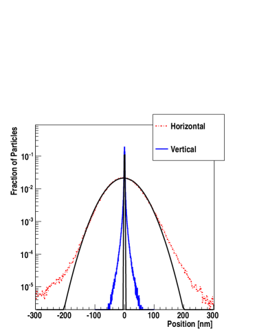
The beam-beam interactions and background pair production has been simulated with GuineaPig [4, 5, 6]. Because the charge distribution of the beams coming from the CLIC accelerator and beam delivery system can not be described by a simple approximation (Figure 2), files containing the proper distribution of particles in the bunches have to be used as an input. A Gaussian approximation to the charge distributions leads to a different amount of background particles. To produce uncorrelated bunch crossings, 312 files each for the electron and positron bunches were used, corresponding to a full CLIC bunch train [7].
 |
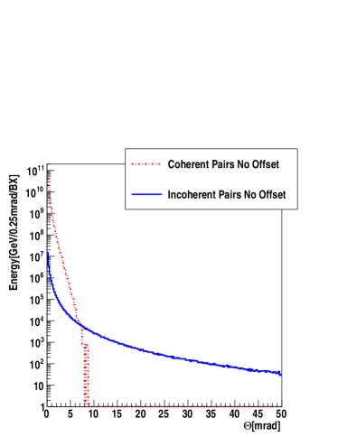 |
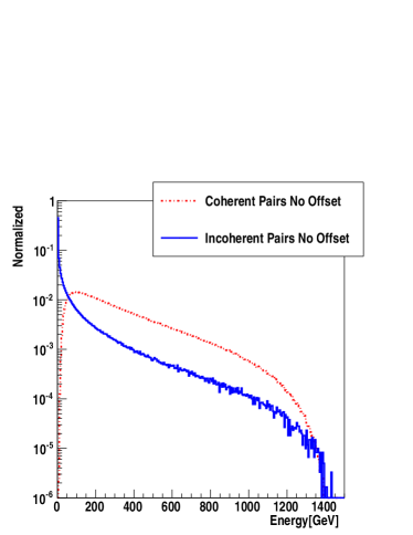
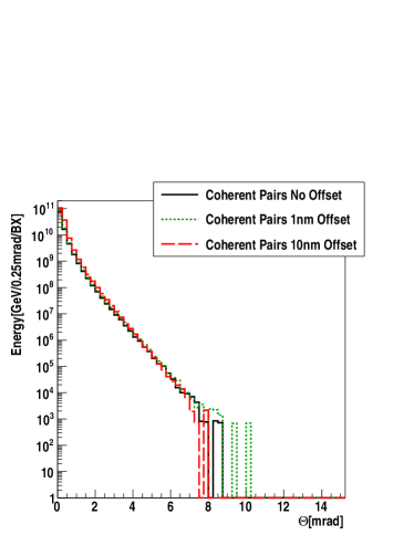
During one bunch crossing at CLIC about particles from incoherent pairs are produced with an energy above 5 MeV. They are called incoherent pairs, because the pair is produced, when real or virtual photons interact with an electron [4]. An electron-positron pair can also be produced, when a photon interacts with the coherent field of the bunch. At CLIC of these so called coherent pairs are produced [8]. Because of their higher cut-off energy (Figure 3 left) the coherent pairs are deflected less by the oncoming bunch and leave the detector without interaction if the outgoing beam pipe and hole in BeamCal are large enough, i.e. approximately 10 mrad (Figure 3 right).
4 Imperfect beam collisions and background
 |
 |
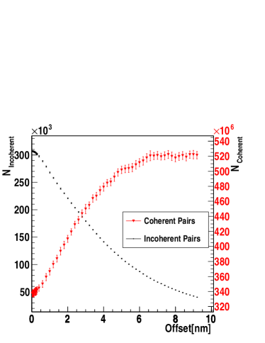
The simulation of the beam-beam interaction is normally done for nominal parameters, however, due to jitter in the accelerator, beam delivery system and final focus quadrupole not all bunch collisions happen without offsets. To study the impact of the vertical offset on the background several GuineaPig runs with a vertical offset varied between 0 and 10 nm have been done. For an offset of 2 nm, 50% of the peak luminosity (with 1% around the nominal energy) is lost. Figure 4 shows the number of pairs produced in the coherent and incoherent process with respect to the offset. For small offsets () the number of both the incoherent and coherent pairs changes less than 5%. Since the luminosity drops rapidly with increasing offsets, this is important because it implies that non-nominal collisions with sufficient luminosity offer the same background environment as the nominal collisions.
High energy electrons can be identified on top of the energy depositions in BeamCal, if the fluctuations of the background is sufficiently small and well known. It is therefore important to know, that the fluctuations in the background from vertical offsets are small. Small vertical offsets should not add significant fluctuations to the energy deposition in BeamCal.
For offsets above 10 nm, when only 2% of the peak luminosity remains, the coherent pairs could pose a problem for the mask, if their angular distribution becomes wider. Figure 4 (right) shows the angular distribution for different offsets, the cut-off fluctuates around 9 mrad so that more statistics are needed for a clear answer.
5 Simulation of the incoherent pair background
 |
 |
Since the coherent pairs are expected to leave the detector without touching any material, only the incoherent pairs from the 312 bunch crossings are simulated in the Geant4 [9] based full detector simulation Mokka [10] with the CLIC detector and forward region. The simulation have been performed with a Geant4 range-cut of 0.005 mm and the QGSP_BERT_HP physics list.
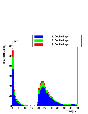
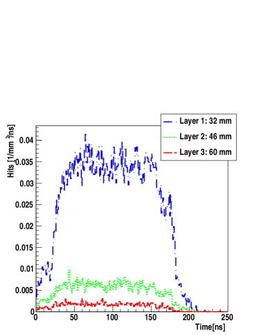
A hit in the VXD is counted if a particle deposits more than 3.4 keV in the silicon of the sensor. No digitization is performed so far. Figure 5 (left) shows time distribution of hits in the VXD after the bunch crossings. A clear separation between hits by particles coming directly from the interaction point and by particles back-scattering from the forward region can be seen. Direct hits can only be reduced by increasing the strength of the solenoid field or the radius of the vertex detector [11]. Back-scattering particles can be influenced by the forward region design. If the hit time is shifted according to the bunch spacing within a train, the realistic hit densities can be estimated as shown on the right in Figure 5. The hit density is low during the first 20 nanoseconds, after which the back-scattered particles start to also hit the vertex detector. If the vertex detector had to integrate over all the hits from full bunch train (i.e. 156 ns) the hit density would correspond to 5.4 hits/mm2, which might have a detrimental effect on the performance of the pattern recognition and vertexing. To limit the impact a fast time-stamping in the order of 5 to 20 nanoseconds is probably needed.
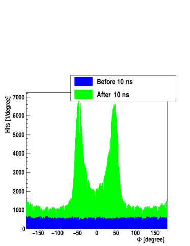
The hit density is comparable to the one found by simulations done for the 500 GeV ILC [12]. In the first layer for a single bunch crossing at CLIC or ILC they are the same with about 0.02 hits/mm2, with a larger VXD radius in the CLIC case. Figure 5 shows that the hit density strongly depends on the radius and decreases for larger radii. Because no Anti-DID field is used at the CLIC detector the distribution of hits is inhomogeneous with respect to the azimuthal angle (Figure 6). This inhomogeneity stems from back-scattering particles only (labeled “After 10 ns”) and occurs when low energy particles coming back from BeamCal curl straight into the VXD. In this region the hit density is considerably higher than the averages shown in Figure 5 (right). The region with the highest number of hits will eventually limit the detector life-time.
6 Conclusions
The incoherent pairs cause a large number of hits in the vertex detector, in the first double layer this corresponds to an average hit density of 5.4 hits/mm2 for a full bunch train. Two thirds of these are coming from back-scattering particles. GuineaPig simulations show that the background environment should not change for small vertical offsets of colliding bunches. The coherent pairs also produced during the collisions should leave the detector region without causing additional background hits, given that the aperture of the beam-pipe is large enough, and this even with potentially large vertical beam offsets at the interaction point.
7 Acknowledgments
I would like to express my gratitude to the Mokka developers, especially Paulo Mora de Freitas, for the help to set up the CLIC_ILD simulation geometry. I would also like to thank Iftach Sadeh and Adrian Vogel for valuable information regarding Mokka and the members FCal collaboration for many discussions.
References
- [1] H. Braun et al., CLIC 2008 Parameters, CLIC-NOTE-764 (2008).
- [2] ILD Concept Group, The International Large Detector Letter of Intent, DESY-09-087 (2009).
- [3] B. Dalena, D. Schulte and R. Tomàs, Impact of the Experiment Solenoid on the CLIC Luminosity, 1st International Particle Accelerator Conference (IPAC), Kyoto, Japan (2010).
- [4] D. Schulte, Study of Electromagnetic and Hadronic Background in the Interaction Region of the TESLA Collider, Ph.D. thesis, University of Hamburg (1996).
- [5] D. Schulte, Beam-Beam Simulations with GUINEA-PIG, 5th International Computational Accelerator Physics Conference, Monterey, CA, USA, CLIC-NOTE 387 (1998).
- [6] GuineaPig CVS Repository, http://isscvs.cern.ch/cgi-bin/viewcvs-all.cgi/gp/?root=placet.
- [7] Files are courtesy of B. Dalena (CERN).
- [8] B. Dalena, Beam-Beam Background in CLIC in Presence of Imperfections, 1st International Particle Accelerator Conference (IPAC), Kyoto, Japan (2010).
- [9] S. Agostinelli et al., Geant4 – A Simulation Toolkit, Nucl. Instrum. Methods Phys. Res., Sect. A 506 3 250 (2003).
- [10] P. Mora de Freitas and H. Videau, Detector Simulation with Mokka/Geant4 : Present and Future, International Workshop on Linear Colliders (LCWS 2002), JeJu Island, Korea (2002).
- [11] D. Schulte, Background at Future Linear Colliders, Workshop on the Development of Future Linear Electron-Positron Colliders for Particle Physics Studies and for Research Using Free Electron Lasers, 59–73, Lund, Sweden, CLIC-Note-424 (1999).
- [12] K. Wichmann, Beam backgrounds: Simulation & Effects on Reconstruction at ILD, International Workshop on Linear Colliders (LCWS 2010), Beijing, China (2010).