Effect of interfacial Cr on magnetoelectricity of Fe2/CrO2/BaTiO3(001)
Abstract
On the basis of first-principles calculations we study the effect of interfacial Cr on the magnetoelectric properties of a composite multiferroic FeL/BaTiO3(001), with the Fe thickness 2 monolayers. The use of the CrO2-terminated interface instead of TiO2 may significantly enhance magnetoelectricity in the system, showing an unexpected change in magnetization induced by the electric polarization reversal. In the case of 2, for instance, the magnetic order of the Fe bilayer can be switched from nearly zero ferrimagnetic to ferromagnetic upon polarization reversal.
pacs:
31.15.Ae, 68.47.Gh, 73.20.At, 77.84.Lf, 77.80.FmI Introduction
The occurrence of ferroelectricity and ferromagnetism in the same phase of a so called multiferroic WangLiuRen:2009 (MF) material allows both a switchable electric polarization, , and a switchable magnetization . More precisely, when an applied electric field displaces the magnetic ions of the multiferroic this affects the magnetic exchange coupling or, vice versa, the external magnetic field, , induces , where is the magnetoelectric (ME) tensor and . When is sufficiently strong this phenomenon may allow to store information in nanometer-sized memories with four logic states Eerenstein:2007p281 ; Cheong:2007p446 ; Zavaliche:2007p7964 .
The classification of multiferroics is based on different mechanisms of induced polarity Khomskii:2009p8591 . The type-I class of multiferroics contains numerous perovskitelike materials in which appears at higher temperatures than magnetism. In these materials, and weakly interact with each other and, therefore, is marginal there. In type-II MF, such as TbMnO3, ferroelectricity is driven by the electronic order degrees related to a spin-orbit mechanism in conjunction mostly with the spin-spiral magnetic arrangement via the Dzyaloshinskii-Moria antisymmetric exchange. The latter creates , where is the vector connecting neighboring spins and . Some of the type-II MFs may disclose a relatively large ME coupling. However, their ferroelectricity is caused by a particular type of magnetic order, which exists only at low temperature and which is predominantly antiferromagnetic.
Studies based on density functional theory (DFT) have significantly contributed to this rapidly developing field of multiferroics PicozziEderer . For instance, calculations from first-principles predict that the ME effect appears when a meV voltage is applied across the interface between the two unlike terminations, such as SrRuO3/SrTiO3 Rondinelli:2008p6059 . The interface ME effect might be intrinsically enhanced by the use of material with high spin polarization. Indeed, a more robust scenario of magnetoelectricity occurs in epitaxially grown two-phase MF consisting of ferroelectric and ferromagnetic components. Ab initio calculations suggest that chemical bonding at the Fe/BaTiO3(001) interface is the source of strong ME coupling Duan:2006p278 ; Fechner2 . Moreover, for the two opposite directions of ( and ), there are rather noticeable differences of 0.1–0.2 in the magnetic moments of interfacial Fe and Ti. This is a very promising phenomenon, which is entirely confined to the ferroelectric/ferromagnetic interface. The interface ME effect Duan:2006p278 defines the change in at the coercive field :
| (1) |
For Fe/BaTiO3(001), the estimated Fechner2 of 210-10 G cm2/V is two orders of magnitude larger than that predicted for SrRuO3/SrTiO3.
Currently, ab initio calculations which explore the trends and basic physics of magnetoelectrics, go ahead of experiment. For a single Fe monolayer (ML) on BaTiO3(001), DFT predicts that perpendicular anisotropy is favored to in-plane anisotropy by 0.7 meV (0.5 meV) per Fe atom for () Fechner2 . Although the spin reorientation transition under switching of is not found from first principles, the ME coupling alters the magnetocrystalline anisotropy energy by 50%. The magnetic order of Fe/BaTiO3 can be tuned by the Fe layer thickness to almost zero- ferrimagnetic upon deposition of a second Fe ML Fechner2 . Ferromagnetic order is restored for the Fe films thicker than 3 ML where the shape anisotropy energy favors in-plane alignment of Duan:2008p6861 . Epitaxial growth of the two-phase MF thin films of high quality continues to be very challenging. A 30-nm thick Fe(001) film has been grown recently on a ferroelectric BaTiO3(001) substrate Yu:2008p7600 . For this composite MF, the trends of magnetic anisotropy are in good agreement with the corresponding ab initio calculations Fechner2 ; Duan:2008p6861 . Until recently, the DFT studies of the interface ME coupling were focused on chemically perfect films and superlattices with no impurities. Modeling the two different Fe3O4/TiO2/BaTiO3(001) interfaces, within the DFT, Niranjan et al. Niranjan:2008p7603 have found that ME coupling is stronger for the O-deficient type of the Fe3O4 interface. Therefore, the presence of extra oxygen or oxygen vacancies at the biferroic interface plays an important role. The effect of iron oxidation on the ME coupling of Fe/TiO3(001) (=Ba, Pb) was simulated Fechner-PRB-2009 from first principles for oxygen coverages ranged between and adsorbed O atom per Fe atom. The calculations suggest that the magnetic properties of the Fe monolayer are gradually degraded with increasing O coverage. However, the change in magnetization which is induced by the reversal remains robust. Thus, the surface oxidation of composite MFs cannot destroy their potentially switchable magnetoelectricity.
It is well known that both the magnetic order of Fe-films and the related magnetic anisotropy are very sensitive to the presence of some other 3d elements. The alloying effect may result in important changes in magnetoelectricity and therefore, the DFT based modelling of chemical order in composite multiferroics would be useful. The effect of Fe-Co alloying on magnetoelectricity of thin-film Fe/BaTiO3(001) has been studied recentlyFeCo-on-BTO from first principles using the coherent-potential approximation to DFT. It was found that the presence of 0.25 Co at.% per Fe atom stabilizes the ferromagnetic order in the two-ML thick and magnetically soft Fe-films. In this work, we investigate the ME coupling in the 1-ML and 2-ML thick Fe on BaTiO3(001) (BTO), with a CrO2 interfacial layer instead of TiO2. Chromium dioxide (CrO2) is an experimentally proven half metal, which shows a Curie temperature of 392 K and which possesses the largest spin polarization so far reported for this class of materials. As a consequence of the half-metallic feature of CrO2 , the occupied Cr 3d bands are fully spin polarized, leading to the spin moment of 2 per formula unit. Now we explore whether such a CrO2-terminated interface of BTO enhances the ME coupling in FeL/BTO(001). In particular, for we observe a dramatic change of magnetization in the topmost Fe ML under polarization reversal.
II Method
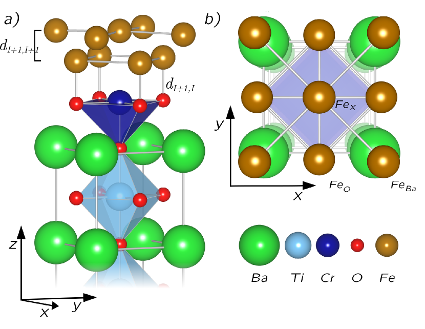
To model the FeL/BaTiO3(001) biferroic system within a slab geometry we used a 5-unit-cell (2-nm) thick BTO supercell covered by an Fe monolayer or Fe bilayer (1,2). A 2-nm-vacuum layer separates the slabs along [001]. For tetragonal BTO the equilibrium lattice parameters 3.943 Å and 1.013 were used. The Fe positions and atomic positions of the two top BTO unit cells were relaxed. In ferroelectric BTO, the cations and O of the alternating BaO and TiO2 layers are displaced against each other in the [001] direction. This leads to spontaneous polarization along [001]. Here we model a dually polar ferroelectric. If the BTO cations are placed above O in the supercell then the negative intralayer displacements form the state pointing parallel to the surface normal () and, vice versa, the state means that the . Before relaxation, the values of 0.082 Å and 0.086 Å were chosen in the TiO2 and BaO layers, respectively fechner1 . The TiO2-terminated type of the BTO interface was energetically preferred fechner1 . In this work, we substitute an interfacial Ti by Cr and added one or two ML of iron on the CrO2-terminated BTO(001). The Fe adatoms of the first ML relax atop oxygen Fechner2 , while the Fe atoms of the second ML find their relaxed positions above the Ba and X=Cr sites. In Figure 1, we plot the side- and top view of relaxed FeL/CrO2/BTO(001) for the case of . The positions of Fe above O, Ba and X are indicated by the corresponding labels in the panel (b).
In this DFT based study we used the Vienna Ab initio Simulation Package (VASP) Kresse94 ; Kresse96 ; Hafner within the local spin-density approximation. The electron-ion interactions were described by projector-augmented wave (PAW) pseudopotentials PAW , and the electronic wave functions were represented by plane waves with a cutoff energy of 650 eV. For ionic relaxation the k-point Monkhorst-Pack Monkhorst1976 mesh was used. The ionic relaxation was performed until the forces were less than eV/Å. To calculate the electronic density of states (DOS) we used the k-point mesh. For each completely relaxed atomic configuration we performed the spin-polarized calculations starting form the ferromagnetic (FM) or, alternatively, from the antiferromagnetic (AFM) configuration in the Fe layers. The induced magnetization of the XO2 interface was as well investigated.
III Results and discussion
Much effort has been recently put to show that the electric field-induced reversal of is able to vary the easy direction of magnetization in magnetically soft Co0.9Fe0.1 Chu-NatMat2009 and Ni0.78Fe0.22 permalloy Lebeugle-PRL2009 attached to thin film of multiferroic BiFeO3 (BFO) or, alternatively, to a single crystal of BiFeO3. There is a problem, however, to form a ferroelectric single domain in the (001) plane of BFO. As a result, the magnetization of permalloy could not be completely switched. We suggest that BTO is a more promising material for switching by an electric field in the FM layer. In our study of the 1-ML-thick Fe-electrode material deposited on BTO(001) we find that the two systems: FeL=1/TiO2/BTO and FeL=1/CrO2/BTO are both ferromagnetically ordered, while the ME coupling coefficient increases from G cm2/V in FeL=1/TiO2/BTO to the value of G cm2/V at the CrO2 interface. Eq.(1) was used to estimate . In the case of Fe bilayer, the magnetic order changes dramatically. The FeL=2/TiO2/BTO system is almost zero- ferrimagnetic for the both states. Contrarily, FeL=2/CrO2/BTO changes its magnetic order from AFM to FM when the substrate polarization is switched from to , resulting in a ME coupling coefficient of G cm2/V. Below we concentrate mainly on the case of .
III.1 Structural relaxation
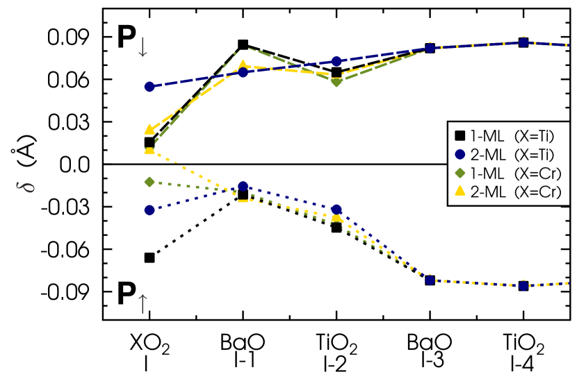
Figure 2 shows the perovskite intralayer displacement between oxygen and cations along [001], , obtained after relaxation of FeL/XO2/BTO(001) (, X=Ti,Cr and ). The interfacial layer and layers beneath are denoted in Fig. 2 by I, I-1, I-2, etc. The asymmetry of seen between and for the layers I, I-1 and I-2 as well as the magnitude of , which gradually decreases towards the interface, both mimic the effect of the depolarizing field and its screening. It should be noted that the state is energetically preferred compared to . For that reason the depolarization effect is rather strong for as shown in Fig.2. For , the value of is stable beneath the interface, namely, between the layers I-1 and I-3 and, therefore, the reduction of becomes crucial at the interface only. It turns out that interfacial CrO2 obeys marginal , which value decreases when the second Fe ML is added. For , the effect of X=Cr on is more pronounced. For instance, when and the presence of Cr changes the sign of in layer I.
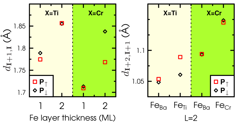
In Figure 3, we plot the relaxed distances between interfacial Fe and O atoms of XO2 (X = Ti, Cr). It has been previously found from first principles that the TiO2 termination of BTO(001) is energetically preferred fechner1 . When the first Fe ML is deposited on TiO2/BTO(001) the Fe atoms find their relaxed positions above O Fechner2 at the distance 1.78 Å as shown in the left panel of Fig. 3. Thus, Fe and O form a strong and relatively short chemical bond at the interface. Our calculations demonstrate that may increase by 5 % when the second Fe ML is added. The polarization reversal shows no effect on . For and the CrO2-interface, we find that the corresponding 1.7 Å is significantly reduced compared to the Fe/TiO2/BTO systems. When the Fe-(I+2) layer is added for X=Cr and , the separation between Fe and O is increased to the corresponding X=Ti value. For the opposite polarization and , a 5 %-increase of was obtained. The latter result suggests a very promissing scenario of magnetoelectricity in the FeL/CrO2/BTO system with . Since the Fe-(I+2) atoms of the second layer are inevitably placed above the perovskite cations, the corresponding FeX and FeBa sites are nonequivalent as shown in Fig. 1. In Fig. 3(b) we plot the relaxed interlayer separation between the Fe layers I+2 and I+1 for the case of . In general, the presence of Cr at the interface makes larger compared to the reference FeL/TiO2/BTO system but, most importantly, is not changed upon P reversal, exept for a 3 %-increase at the FeTi site.
III.2 Electronic and magnetic properties
Fig. 4 shows the site-projected DOS of paraelectric cubic BaTiO3 together with the DOS of hypothetic cubic BaCrO3. The two perovskites were calculated using the same lattice parameter Å. For BTO we obtained an insulating band gap of 2 eV, which is typically underestimated within the local density approximation.
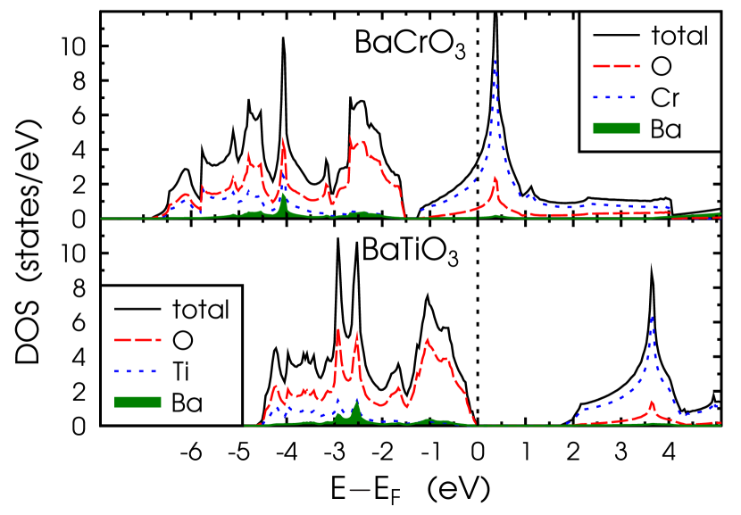
The conduction band of BTO is formed mainly by the Ti 3 states whereas the upper valence band is largerly composed by the O 2 states. In BaCrO3, the DOS is typically metallic while the 3 states of Cr dominate near the Fermi level, . There is a marginal pseudogap seen at -1.5 eV below . Therefore, one can expect relatively strong metallization at the Fe/CrO2 interface compared to Fe/TiO2.
| Site | Layer | (Fe2)L=1/CrO2/BTO | (Fe2)L=2/CrO2/BTO | (Fe2)L=1/TiO2/BTO | (Fe2)L=2/TiO2/BTO | ||||
|---|---|---|---|---|---|---|---|---|---|
| Fe | (I+2) | — | — | — | — | ||||
| Fe | (I+2) | — | — | — | — | ||||
| Fe | (I+1) | ||||||||
| X | (I) | ||||||||
| O | (I) | ||||||||
| (eV) | |||||||||
| () | |||||||||
| (G cm2/V) | 3.05 | ||||||||
In FeL=1/TiO2/BTO the FM order is energetically favorable against the AFM solution by 0.7 eV/cell (0.75 eV/cell) for (). Here, the Fe and O magnetic moments are aligned parallelly whereas the Ti magnetic moment, originating from hybridization of the Ti and Fe minority states Duan:2006p278 , is antiparallelly aligned. All magnetic moments of the system are collected in Table 1. The polarization reversal from to yields the magnetization change /cell which formally results in the ME coupling of 2.1 G cm2/V. When Cr substitutes Ti at the interface, the lowest-energy configuration remains ferromagnetic. However, the negative magnetic moment of 2 , induced on Cr, is much larger than . For interfacial oxygen the calculated magnetic moment is about 0.1 . This value as well as are in a good agreement with the experimental data of bulk CrO2 Huang2002 . Due to the large and negative Cr magnetic moment, the total magnetization of the system FeL=1/CrO2/BTO is reduced by in comparison to that of FeL=1/TiO2/BTO. Although is moderately changed by reversal the corresponding results in 7.2 G cm2/V, which is three times larger than the ME effect of FeL=1/TiO2/BTO.
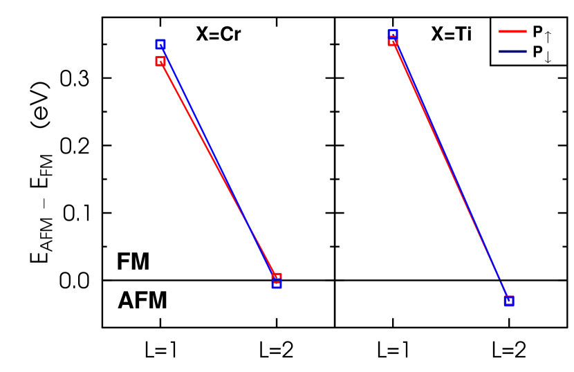
The second Fe ML deposited on the TiO2-terminated BTO(001) interface causes a specific case. There are two inequivalent I+2 sites situated atop Ba and Ti, respectively, which are labelled by FeBa and FeX in Fig. 1. The different magnetic moments reflect the neighbourhood of these atoms such as their atomic volumes and hybridization of the electronic states. Let us consider, first, the case of X=Ti. The value of in the layer I+1 is almost quenched while the two sizable moments in the surface layer I+2 are antiparallelly aligned. This results in for FeL=2/TiO2/BTO(001). In the case of the Fe bilayer on the CrO2-terminated BTO, the lowest-energy configuration is antiferromagnetic for and becomes ferromagnetic for . For this polarization the Fe magnetic moments in the layer I+1 are far below their bulk value but the two Fe-(I+2) magnetic moments, which are ferromagnetically aligned to each other, contribute significantly to the total . We estimate that the total magnetic moment of the system changes from 0.3 to 8 per unit cell area upon polarization reversal. Thus, the polarization reversal produces for X=Cr the effect of switchable magnetization. In Fig. 5, the difference in energy, , calculated between the AFM and FM configurations and normalized per Fe atom, is plotted. For X=Cr the 2-ML-thick Fe film represents a specific case of a magnetically soft system at fixed . Nevertheless, any magnetic switch upon reversal requires an energy which exceeds the coercive field value of BTO.
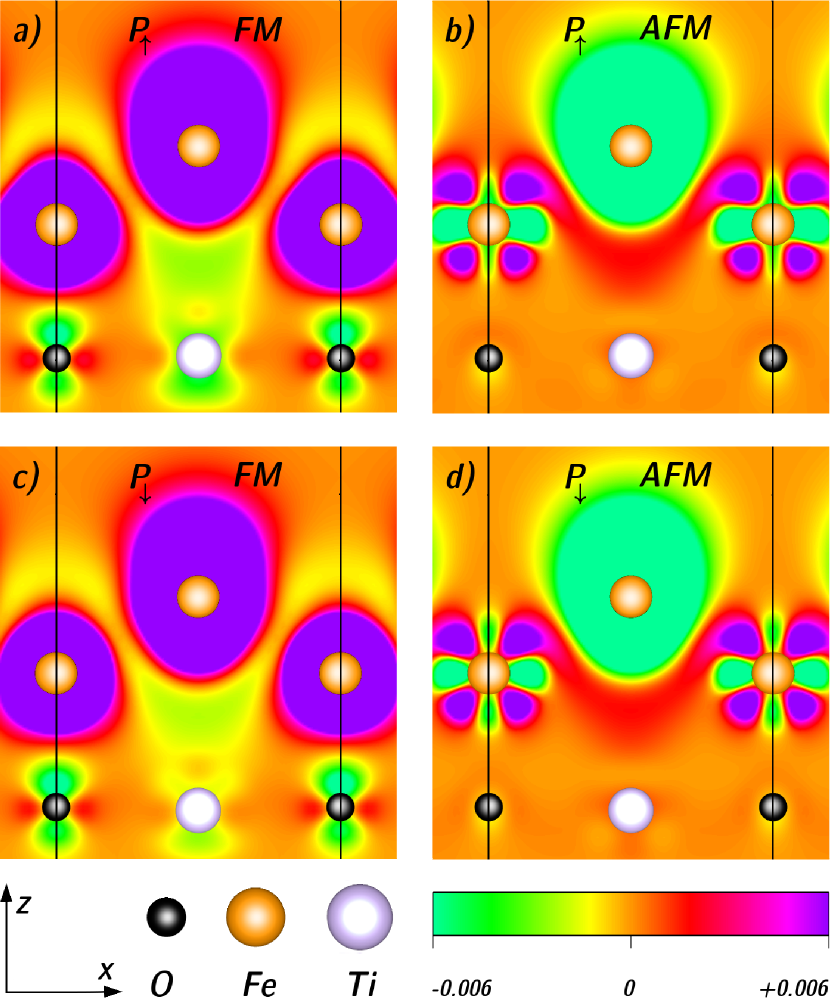
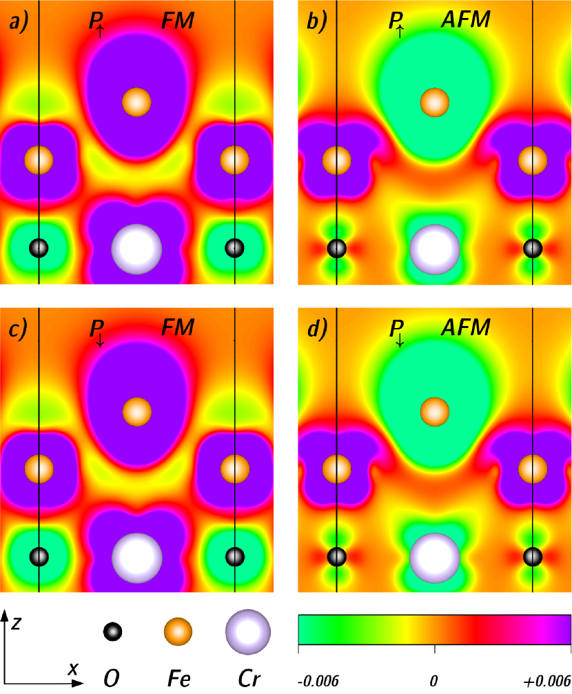
To illustrate the interface ME coupling mechanism, we plot in Fig. 6 and Fig. 7 the spin density imbalance, (), obtained under -reversal near the interface of FeL=2/TiO2/BTO and FeL=2/CrO2/BTO, respectively. The (100) plane cutting through the X and O interfacial sites shows where the largest changes of the spin density occur and, hence, from where the ME effect arises. Each of the four panels of Fig. 6–7 shows the local magnetization density calculated at fixed (). These are shown for the two possible magnetic configurations which are either FM or AFM. For X=Ti, both the - and -poled states are antiferromagnetically ordered, as shown in the panels (b) and (d) of Fig. 6. The two results are similar to each other. The largest negatively charged areas are seen around FeX-(I+2) while the - charged areas around the second Fe site of this layer are not shown in Fig. 6. All other sites of FeL=2/TiO2/BTO including Fe-(I+1) indicate very small magnetic moments. Inspecting the spin density imbalance seen in Fig.7(a) and Fig.7(d) for the two energetically preferred but oppositely poled configurations of X=Cr, we find many differences in the magnetic structure. The panel (a) shows the ferromagnetically ordered state where the Fe and Cr atoms form rather spacious regions of positive spin density while can be spotted around O, in the Fe interstitials and regions towards the surface. In the case of , the energetically favorable AFM configuration, shown in the panel (d), is similar to that of FeL=2/TiO2/BTO. Here, the large areas around FeX-(I+2) and also around interfacial Cr are negatively charged. Besides, the pz-orbitals of interfacial O show their negative spin population resulting from hybridization with the 3 states of Fe-(I+1) whereas the O px and py orbitals, which form the bonds with the Cr 3d states, contribute to . Regarding the Fe-(I+1) atoms of FeL=2/CrO2/BTO, Fig.7(d) shows that they contribute to contrarily to the case of X=Ti.
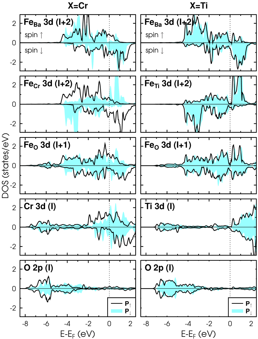
The site-projected and spin-resolved DOS calculated for FeL=2/XO2/BTO are plotted in the two panels of Fig. 8. For each system, the solid (shaded) lines represent the DOS curves in the () state. The energetically preferable magnetic configurations are shown only in Fig. 8 for each direction of . In general, the DOS of the interfacial XO2 layer is metallic for both systems. For and X=Cr, however, the Cr 3–DOS indicates relatively strong spin polarization at the Fermi level. This is not surprising since the DOS of hypothetical BaCrO3 shows similar behavior, as shown in Fig. 4. When X=Ti, there is some insignificant presence of the Ti 3 states in the BTO band gap below , which entirely results from the hybridization with the Fe states of the layer I+1. Another major difference in the DOS seen in Fig. 8 for comes from the magnetic ordering of FeX. For X=Ti the two Fe atoms in the topmost layer I+2 are coupled antiferrimagnetically while the corresponding DOS curves show minor changes upon P reversal. When X=Cr the polarization reversal from to the state supports (i) the ferromagnetic order in the layer I+2, (ii) the relatively large magnetic moment (FeO)0.9 in the layer I+1 and (iii) the 2- change of which is aligned parallelly to the Fe magnetic moments.
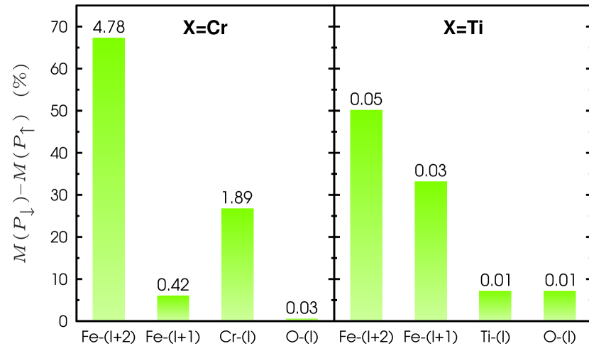
In Fig. 9, we plot the relative (in %) and absolute contributions (in ) to coming from each magnetic species of FeL=2/XO2/BTO. For the two biferroic interfaces studied here, the largest -induced change of comes from the Fe-(I+2) atoms. For X=Cr, however, the absolute value of approaches 7 per unit cell. As result, the corresponding ME coupling coefficient increases significantly compared to that of X=Ti. We demonstrate that the case of and X=Cr stabilizes the FM ordering in the system with P pointing upwards. Surprisingly, this is completely due to rather modest 5 % decrease of under P reversal, as shown in Fig. 3. With decreasing above CrO2, the FM order is developing in the system. More precisely, when the Fe-(I+1) magnetic moment becomes larger ferromagnetism is stabilized in layer (I+2). In the case of X=Ti, the interlayer separations and are almost the same upon the P reversal that prevents any crucial spin reorientation in the topmost Fe ML.
IV Conclusions
In summary, we present an ab initio study of the effect of interfacial Cr on the strength of magnetoelectric coupling seen at the interface of multiferroic FeL/CrO2/BaTiO3(001), with the Fe thickness 2 monolayers. We predict that a CrO2-terminated interface instead of TiO2 may significantly enhance magnetoelectricity in the system. The most attractive scenario is, however, obtainded for the Fe bilayer where the magnetic order changes from nearly zero- ferrimagnetic to ferromagnetic upon polarization reversal in ferroelectric BaTiO3(001).
V Acknowledgments
This work was supported by the Collaborative Research Network SFB 762, ’Functionality of Oxidic Interfaces’. M. Fechner is a member of the International Max Planck Research School for Science and Technology of Nanostructures.
References
- (1) K. F. Wang, J.-M. Liu, and Z. F. Ren, Advances in Phys. 58, 321 (2009).
- (2) W. Eerenstein, M. Wiora, J. L. Prieto, J. F. Scott, and N. D. Mathur, Nature Mater. 6, 348 (2007).
- (3) S.-W. Cheong, Nature Mater. 6, 927 (2007).
- (4) F. Zavaliche, T. Zhao, H. Zheng, F. Straub, M. P. Cruz, P.-L.Yang, D. Hao, and R. Ramesh, Nano Lett. 7, 1586 (2007).
- (5) D. Khomskii, Phys. 2, 20 (2009).
- (6) M. Fiebig, J. Phys. D: Appl. Phys. 38, R123 (2005).
- (7) S. Picozzi and C. Ederer, J. Phys.: Condens. Matter. 21, 303201 (2009).
- (8) J. M. Rondinelli, M. Stengel, N. A. Spaldin, Nat. Nanotechnol. 3, 46 (2008).
- (9) C.-G. Duan, S. S. Jaswal, E. Y. Tsymbal, Phys. Rev. Lett., 97, 047201 (2006).
- (10) M. Fechner, I. V. Maznichenko, S. Ostanin, A. Ernst, J. Henk, P. Bruno, I. Mertig, Phys. Rev. B 78, 212406 (2008).
- (11) C.-G. Duan, J. P. Velev, R. F. Sabirianov, W. N. Mei, S. S. Jaswal, E. Y. Tsymbal, Appl. Phys. Lett. 92, 122905 (2008).
- (12) C. Yu, M. Pechan, S. Srivastava, C. J. Palmstrom, M. Biegaslski, C. Brooks, D. Schlom, J. Appl. Phys. 103, 07B108 (2008)
- (13) M. K. Niranjan,J. P. Velev, C.-G. Duan, S. S. Jaswal, E. Y. Tsymbal, Phys. Rev. B 78, 104405 (2008).
- (14) M. Fechner, S. Ostanin and I. Mertig, Phys. Rev. B 80, 094405 (2009).
- (15) I.V. Maznichenko, M. Fechner, S. Ostanin, A. Ernst, J. Henk, I. Mertig, J.B. Staunton, unpublished.
- (16) M. Fechner, S. Ostanin, I. Mertig, Phys. Rev. B 77, 094112 (2008).
- (17) G. Kresse and J. Hafner, Phys. Rev. B 49, 14251 (1994).
- (18) G. Kresse and J. Furthmüller, Phys. Rev. B 54, 11169 (1996).
- (19) J. Hafner, J. Comput. Chem. 29, 2044 (2008).
- (20) G. Kresse and D. Joubert, Phys. Rev. B 59, 1758 (1999).
- (21) H. J. Monkhorst and J. D. Pack, Phys. Rev. B 13, 5188 (1976).
- (22) Y.-H. Chu, L. W. Martin, M. B. Holcomb, M. Gajek, S.-J. Han, Q. He, N. Balke, C.-H. Yang, D. Lee, W. Hu, Q. Zhan, P.-L. Yang, A. Fraile-rodríguez, A. Scholl, S. X. Wang, and R. Ramesh, Nature Mat. 7, 478 (2008).
- (23) D. Lebeugle, D. Colson, A. Forget, M. Viret, A.M. Bataille and A. Gukasov, Phys. Rev. Lett. 100, 227602 (2009).
- (24) D. J. Huang, H. T. Jeng, C. F. Chang, G. Y. Guo, J. Chen, W. P. Wu, S. C. Chung, S. G. Shyu, C. C. Wu, H. J. Lin, C. T. Chen, Phys. Rev. B 66, 174440 (2002).