THz emission from a stacked coherent flux-flow oscillator: non-local radiative boundary conditions and the role of geometrical resonances.
Abstract
I derive simple non-local dynamic boundary conditions, suitable for modelling of radiation emission from stacked Josephson junctions, and employ them for analysis of flux-flow emission from intrinsic Josephson junctions in high- superconductors. It is shown that due to the lack of Lorenz contraction of fluxons in stacked junctions, high quality geometrical resonances are prerequisite for high power emission from the stack. This leads to a dual role of the radiative impedance: on the one hand, small impedance increases the efficiency of emission from the stack, on the other hand, enhanced radiative losses reduce the quality factor of geometrical resonances, which may decrease the total emission power. Therefore, the optimal conditions for the coherent flux-flow oscillator are achieved when radiative losses are comparable to resistive losses inside the stack.
pacs:
74.72.Hs, 74.78.Fk, 74.50.+r, 85.25.CpCreation of a compact, high power THz source remains a difficult technological challenge, colloquially known as “the THz gap” THzGap . Flux-flow oscillators (FFO’s), based on regular motion of quantized vortices (fluxons) in Josephson junctions, can generate tunable THz radiation with a remarkable linewidth , albeit with a low emission power Koshelets . The power could be greatly enhanced by coherent phase-locking of several coupled FFO’s Barbara ; SakUst . The required coupling is strongest in stacked, atomic scale intrinsic Josephson junctions (IJJs), naturally formed in layered high temperature superconductor (Bi-2212). IJJs allow simple integration of a large number of almost identical stacked Josephson junctions. Furthermore, a large superconducting energy gap in Bi-2212 SecondOrder facilitates operation in the important THz frequency range (up to 10THz). Therefore, IJJs are actively studied both theoretically FFlowSimul ; FFlowMachida ; Bul2007 ; Cascade ; Hu ; Savelev and experimentally Cherenkov ; Batov ; Bae2007 ; Ozyuzer ; FiskeInd ; SvenFiske as possible candidates for realization of a coherent THz oscillator.
Proper radiative boundary conditions are essential for analysis of the coherent FFO. For a single junction this can be done by introducing an appropriate radiation impedance Bul2006 , connecting local ac-components of electric and magnetic fields at the junction edges.
| (1) |
The emission power is , where is the ac-voltage, is the junction barrier thickness and
| (2) |
is the radiative resistance of a single junction, is the width of the junction. However, the stacked FFO can not be described by a single because the effective radiative resistance depends not only on the geometry of the stack, but also in a crucial way on the collective fluxon configuration. For example, motion of the triangular fluxon lattice corresponds to because it results in out-of-phase oscillations in neighbor junctions , leading to destructive interference and negligible emission. On the other hand, motion of the rectangular lattice corresponds to small because it results in in-phase oscillation , leading to constructive interference and coherent enhancement of the emission power , where is the number of junctions in the stack. Such behavior is caused by the essentially non-local nature of magnetic induction Fluxon , which is the consequence of the inductive coupling of junctions in the stack. Therefore, the relation between local and non-local can not be described by Eq. (1).
In this letter I derive simple non-local dynamic radiative boundary conditions for stacked Josephson junctions and employ them for analysis of flux-flow emission from IJJ-based stacked FFO. It is shown that due to the lack of Lorenz contraction of fluxons in stacked junctions Fluxon , high quality geometrical resonances are prerequisite for high power emission from the stack. This leads to a dual role of the radiative impedance: on the one hand, small increases the emission efficiency, but on the other hand, enhanced radiative losses reduce of geometrical resonances, which leads to reduction of the emission power. The maximum power is achieved when radiative losses are equal to internal losses in the stack.
Neumann (static) boundary conditions are most widely used for numerical modelling of Josephson junctions:
| (3) |
Here is the Josephson phase difference, are coordinates of junction edges, is the applied dc-magnetic field, is the Josephson penetration depth and is the effective magnetic thickness of the junction Fluxon . As emphasized in Ref. Bul2006 , Neumann boundary conditions are non-radiative because they assume .
Radiative (dynamic) boundary conditions should account for the finite . For a single junction they can be easily written with the help of Eq. (1) Hu ; Bul2006 :
| (4) |
Here plus and minus signs correspond to and , respectively, because the direction of emission is opposite at opposite edges of the junction.
However, Eq.(4) is not directly applicable for stacked junctions due to the principle difference in electrodynamics, which is local in single, and non-local in stacked junctions. The electric field is local in each junction because the Debye screening length is always smaller than the electrode thickness , even for IJJs. However, the magnetic field in inductively coupled stacked junctions is non-local and is created and shared cooperatively by the whole stack Fluxon . The non-locality of is particularly dramatic for IJJs, for which the London penetration depth nm is much larger than nm.
To derive the proper non-local radiative boundary conditions for stacked Josephson junctions, lets note that the local relation Eq.(1) is valid outside the stack, however, here the electric field is the result of interference of electric fields from all junctions:
| (5) |
The net emission power from one edge of the stack is
| (6) |
Radiative losses are associated with additional currents flowing through edges of the stack:
| (7) |
Those displacement-like currents should be added in the numerical scheme for the sake of energy conservation. Equations (4,5,7) together form the final non-local dynamic boundary conditions for stacked Josephson junctions. For the out-of-phase state, , , they reduce to the non-radiative Neumann condition Eq.(3). For the in-phase state, , , they lead to coherent power amplification , Eq.(6).
To calculate flux-flow emission, the non-local boundary conditions were implemented into the coupled sine-Gordon equation SakUst , which describes electrodynamics of inductively coupled stacked Josephson junctions (see Refs.Modes ; Fluxon for details of the formalism and the Supplementary Supplem for technical details). Simulations were made for identical IJJs with m, m, the stacking periodicity nm, the electrode thickness nm, the ratio of the barrier thickness to the relative dielectric constant nm, nm, and the critical current density A/cm2. Those parameters correspond to m, the Josephson plasma frequency 1/s, and the slowest velocity of light m/s, typical for small Bi-2212 mesa structures Katterwe ; SvenFiske . The damping parameter , corresponds to junction resistance and the axis resistivity cm, equal to large bias tunnel resistivity of IJJs Doping . However, the quasiparticle (QP) resistivity at small bias and low can be up to two orders of magnitude larger Katterwe2008 . Therefore, represents the highest limit of QP damping in IJJs. The correct is important for numerical modelling because it determines in the absence of radiative losses. Simulations were also performed for smaller down to , which show qualitatively similar behavior SvenFiske , but require substantially longer integration times. However, for larger the number and amplitudes of accessible geometrical resonances were significantly reduced.
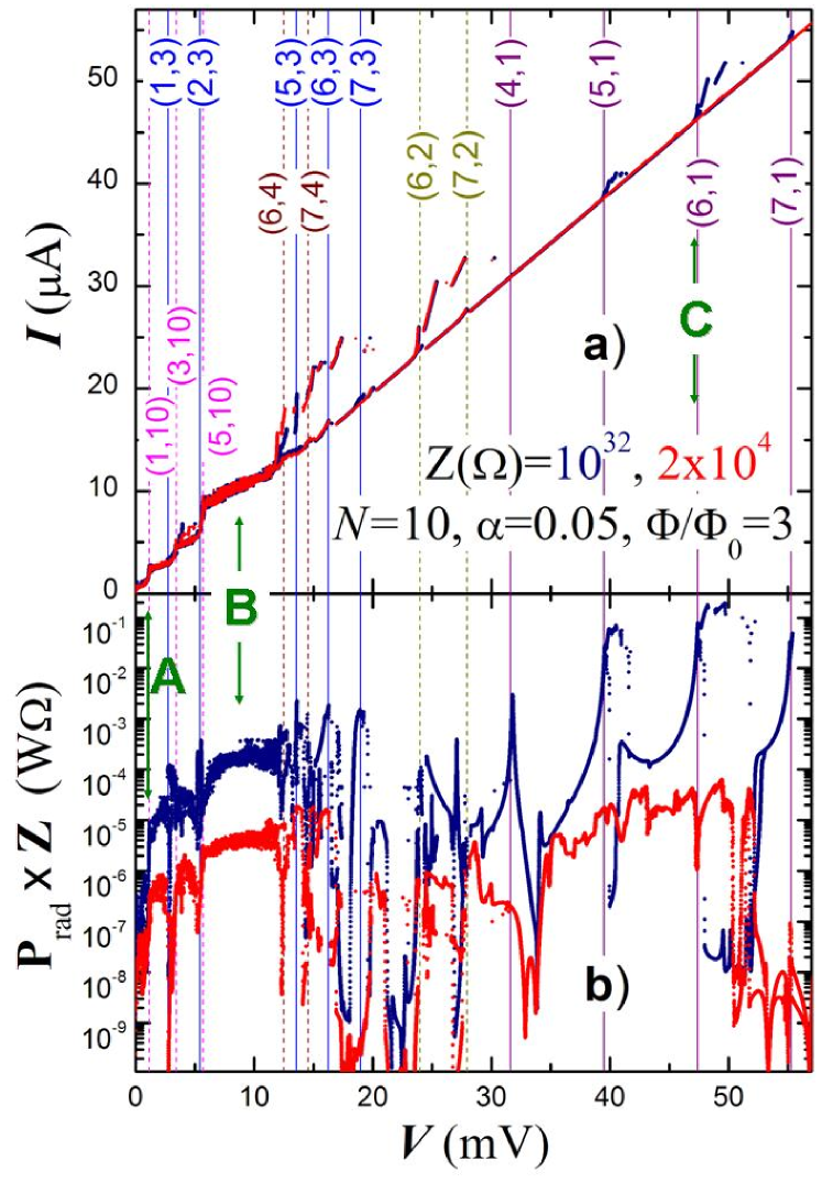
Fig. 1 a) shows simulated characteristics for two impedance values, corresponding to negligible (dark blue) and moderate (red curve) radiation losses, at , where is the flux per junction. Data for are similar to simulations with non-radiative Neumann boundary conditions FFlowSimul ; FFlowMachida ; SvenFiske . A large variety of Fiske steps is seen.
Geometrical (Fiske) resonances are caused by resonant excitation of phonon-like collective fluxon lattice vibrations SvenFiske in the flux-flow state. In stacked junctions such fluxon phonons are two-dimensional and are characterized by two wave numbers in plane, and in the -axis direction KleinerModes . Unlike Josephson plasma waves, fluxon phonons have a linear dispersion relation at low frequencies. Fluxon phonons with the wave number propagate with the in-plane velocity KleinerModes . The slowest, , corresponds to the out-of-phase, , and the fastest, , to the in-phase, , mode. Fiske steps occur when the ac-Josephson frequency coincides with the frequency of one of the cavity modes SvenFiske :
| (8) |
In Fig. 1, voltages of the most prominent phase-locked Fiske steps are marked by vertical lines together with mode numbers . For the non-radiative case , Fiske steps with both even and odd are equally represented. However, for we observe a clear difference between even and odd resonances: even- steps, e.g. (1,10), (3,10), (5,10), (6,4), (7,4), (6,2) and (7,2) are practically the same as for , but all odd- steps are strongly reduced. For example, steps (5,3), (5,1) and (6,1) are well developed for , but not present for .
The observed difference between even and odd- steps for is due to appearance of significant radiative losses. For the considered case of even , all even- resonances are interfering destructively and therefore are non-emitting. To the contrary all odd- resonances are emitting progressively stronger with decreasing the mode number . This is most clearly seen from the voltage dependence of the normalized emission power, shown in Fig. 1 b). It can be seen that for even- Fiske steps (dashed lines) correspond to minima, while odd- steps (solid lines) to maxima of emission. As expected, the largest (by two orders of magnitude) emission occurs for in-phase resonances (5,1), (6,1) with the largest Fiske step amplitudes, see Fig. 1 a). They correspond to the velocity matching condition , as discussed in Ref. SvenFiske . The Fiske step (5,3) has larger amplitude but smaller emission because only one third of the stack is emitting coherently while the rest of the junctions are interfering destructively. Also odd- Fiske steps (1,3), (3,3), (6,3), (7,3), (4,1), (7,1) with small amplitudes, see Fig. 1 a), produce clear emission peaks for .
Remarkably, all these emission peaks are absent for . Furthermore, the strongest emission peaks (5,1), (6,1) at are replaced by minima for . Apparently, radiative losses have completely damped in-phase resonances for . This clearly illustrates that the quality factor is playing a central role in operation of the coherent FFO.
The role of the output impedance on the FFO power can be understood from the following simple model. The oscillating amplitude at the resonance is , where is the amplitude out of the resonance and is the effective damping resistance due to both internal QP () and radiative () losses:
| (9) |
The total emission power from one side of the junction is
| (10) |
It is useful to consider the quantity
| (11) |
where is constant for a given resonance .
As already discussed above, see Eqs. (5,6), radiative losses in stacked Josephson junctions depend essentially on the collective, rather than local, fluxon dynamics. They can be described by the “coherence factor”:
| (12) |
which reflects the efficiency of emission in comparison to a single junction with the same electric field amplitude. The effective radiative resistance (per junction) is then:
| (13) |
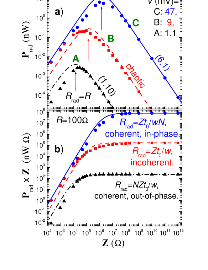
Fig. 2 shows a) the emission power (from one edge) and b) the product , as a function of for three voltage levels, marked by arrows in Fig. 1: A - the coherent, phase-locked state at the lowest out-of-phase geometrical resonance mV; B - an incoherent, chaotic state at mV at which no clear resonances are observed and individual junctions are having different voltages; C - the coherent in-phase resonance mV. Symbols and lines represent numerical simulations and analytic expressions, Eqs. (10,11), respectively. It is seen that at large , is constant. In this case radiative losses are small compared to QP losses, , the amplitude is independent of and is increasing with decreasing , see Eq.(6). However, for , the quality factor starts to decrease, resulting in reduction of and the emission power.
According to Eq. (10), the maximum of is achieved when . However, as follows from Eq. (13), for stacked junctions is not constant, but depends on the collective state of the stack, described by the coherence factor . For the in-phase state C, and . The corresponding and calculated from Eqs. (10,11) are shown by solid lines in Figs. 2 a) and b) and describe well the numerical data. In this case the maximum of is achieved at large , marked by the blue arrow in Fig. 2 a). The incoherent/chaotic state B, is well described by Eqs. (10,11) with times larger (dashed lines), because junctions in the stack act as individual single junctions, . Finally, as expected, the out-of-phase state corresponds to the largest which is, however not infinite, but fairly well described by yet another times larger , , represented by the dashed-dotted lines.
To conclude, strong emission from the stacked coherent flux-flow oscillator requires both large coherence factor and large oscillating amplitude . For a single junction FFO, can be greatly enhanced due to Lorentz contraction of the fluxon Laub at the velocity matching condition Koshelets . However, such mechanism is absent in stacked Josephson junctions due to the lack of Lorentz invariance in the system Fluxon . Therefore, large can be achieved only in the presence of a high quality resonance. Importantly, high quality geometrical resonances can impose their order on the fluxon lattice. E.g., fast in-phase fluxon phonons may stabilize the rectangular fluxon lattice with large even at low fluxon velocities SvenFiske . In addition, the resonance reduces the linewidth of emission . Therefore, high speed geometrical resonances are particularly important for realization of the coherent stacked FFO. As shown above, optimal operation of the coherent FFO is achieved when radiative losses are equal to internal resistive losses. Finally, it was shown that radiative losses lead to the asymmetry between even/odd- Fiske steps in s of stacked Josephson junctions. This is consistent with resent experimental observations for Bi-2212 mesas SvenFiske and can be viewed as indirect evidence for significant coherent flux-flow emission from intrinsic Josephson junctions.
References
- (1) B. Ferguson and X.C. Zhang, Nature Photonics 1, 26 (2002).
- (2) V.P. Koshelets and S.V. Shitov, Supercond. Sci.Technol. 13, R53 (2000).
- (3) P. Barbara, A.B. Cawthorne, S.V. Shitov, and C.V. Lobb, Phys. Rev. Lett. 82, 1963 (1999)
- (4) S. Sakai, A.V. Ustinov, N. Thyssen and H. Kolstedt, Phys. Rev. B 58, 5777 (1998).
- (5) V.M. Krasnov, Phys. Rev. B 79, 214510 (2009).
- (6) R. Kleiner, T. Gaber and G. Hechtfischer, Physica C 362, 29 (2001).
- (7) M. Machida, T. Koyama, A. Tanaka and M. Tachiki, Physica C 330, 85 (2000).
- (8) L.N. Bulaevskii and A.E. Koshelev, Phys. Rev. Lett. 99, 057002 (2007).
- (9) V.M. Krasnov, Phys. Rev. Lett. 103, 227002 (2009).
- (10) S. Savel’ev, V.A. Yampolskii, A.L. Rakhmanov and F. Nori, Rep. Prog. Phys. 73, 026501 (2010).
- (11) X. Hu and S.Z. Lin, Supercond. Sci. Techn. 23, 053001 (2010).
- (12) G. Hechtfisher, R. Kleiner, A.V. Ustinov, and P. Müller, Phys. Rev. Lett. 79, 1365 (1997).
- (13) I.E. Batov et al., Appl. Phys. Lett. 88, 262504 (2006).
- (14) L. Ozyuzer et al., Science 318, 1291 (2007).
- (15) M.H. Bae, H.J. Lee, and J.H. Choi,, Phys. Rev. Lett. 98, 027002 (2007).
- (16) H.B. Wang et al., Appl. Phys. Lett. 89, 252506 (2006).
- (17) S.O. Katterwe, A. Rydh, H. Motzkau and V.M. Krasnov, cond-mat (May 2010) (unpublished).
- (18) L.N. Bulaevskii and A.E. Koshelev, Phys. Rev. Lett. 97, 267001 (2006).
- (19) V.M. Krasnov, Phys. Rev. B 63, 064519 (2001).
- (20) V.M. Krasnov and D. Winkler, Phys. Rev. B 56, 9106 (1997).
- (21) The variety of collective dynamic states in the stack can be seen form the demo-program provided in the Supplementary: see EPAPS Document No…
- (22) S.O. Katterwe and V.M. Krasnov, Phys. Rev. B 80, 020502(R) (2009).
- (23) V.M. Krasnov et. al, Phys. Rev. B 65, 140504(R) (2002).
- (24) S.O. Katterwe, A. Rydh and V.M. Krasnov, Phys. Rev. Lett. 101, 087003 (2008).
- (25) R. Kleiner, Phys. Rev. B 50, 6919 (1994).
- (26) A.Laub, T.Doderer, S.G.Lachenmann and R.P.Huebener, Phys. Rev. Lett. 75, 1372 (1995).