Plasmonic Cloaking of Cylinders:
Finite Length, Oblique Illumination
and Cross-Polarization Coupling
Abstract
Metamaterial cloaking has been proposed and studied in recent years following several interesting approaches. One of them, the scattering-cancellation technique, or plasmonic cloaking, exploits the plasmonic effects of suitably designed thin homogeneous metamaterial covers to drastically suppress the scattering of moderately sized objects within specific frequency ranges of interest. Besides its inherent simplicity, this technique also holds the promise of isotropic response and weak polarization dependence. Its theory has been applied extensively to symmetrical geometries and canonical 3D shapes, but its application to elongated objects has not been explored with the same level of detail. We derive here closed-form theoretical formulas for infinite cylinders under arbitrary wave incidence, and validate their performance with full-wave numerical simulations, also considering the effects of finite lengths and truncation effects in cylindrical objects. In particular, we find that a single isotropic (idealized) cloaking layer may successfully suppress the dominant scattering coefficients of moderately thin elongated objects, even for finite lengths comparable with the incident wavelength, providing a weak dependence on the incidence angle. These results may pave the way for application of plasmonic cloaking in a variety of practical scenarios of interest.
I Introduction
The application of metamaterials to cloaking and invisibility has been explored in several exciting papers in recent years Pendry2006 ; Schurig2006 ; Cai2007 ; Leonhardt2006 ; Milton2005 ; Milton2006 ; Greenleaf2007 ; Miller2006 ; Yaghjian2008 ; Alitalo2008 ; Tretyakov2009 ; Castaldi2009 ; Lai2009a ; Lai2009b ; Alu2005a . In these contributions, several alternative realizations and techniques have been discussed, and the exotic properties of several classes of metamaterials have been shown to be possibly tailored in order to provide much reduced scattering from finite-sized objects in different configurations and schemes, for a wide range of frequencies of interest. Recent reviews of the various possibilities are available for the interested reader (see e.g. Refs. Alitalo2009 ; Alu2008a ).
One such possibility takes advantage of the anomalous scattering response of thin plasmonic layers. As shown in Ref. Alu2005a , artificial plasmonic materials with low or negative effective permittivity may provide scattering cancellation via their local negative polarizability. This technique, called plasmonic cloaking, is consistent with earlier works that have speculated how a composite particle combining positive and negative permittivity may provide identically zero scattering in the static limit Kerker1975 . Recent study of the dynamic case has shown that plasmonic cloaks may suppress not only the dominant dipolar scattering from moderately sized objects, but also higher-order multipolar orders for larger scatterers Alu2008b . In this vein, it is worth stressing that by “cloaking” we mean strong, or maximized, scattering reduction over a finite frequency band – not necessarily complete invisibility, since residual scattering orders may always make the scatterer detectable to a certain extent. Still, significant reduction of visibility is achievable with the proper plasmonic cloak design, as shown in several recent papers Alu2007a ; Alu2008c ; Alu2008d ; Alu2007b ; Alu2008e ; Alu2008f ; Alu2009a ; Alu2009b ; Tricarico2010 and as discussed in the following.
Plasmonic cloaking has been shown to offer several intriguing properties in a variety of setups. Examples include intrinsic robustness to frequency and design variations Alu2007a ; Alu2008c ; Alu2008d , straightforward extension to arbitrary collections of objects Alu2007b and multi-frequency operation Alu2008e ; Alu2008f . Moreover, the admission of fields inside the cloaked region, peculiar to this technique, may be used to suppress the inherent scattering from receiving antennas and sensing devices, which may open several interesting venues in non-invasive probing and sensing applications Alu2009a . Extensions to ultrathin surface cloaks have also been put forward in this same context Alu2009b . All these studies were conducted, for simplicity, for a canonical spherical object, illuminated by a generic polarization of the impinging field. Recent studies Tricarico2010 have shown that analogous concepts may be applied to more complex 3D geometries, based on the overall robustness of the integral cancellation effect.
However, in several practical applications, in particular for the radar community, elongated objects may become of specific interest for these applications. Ref. Alu2005a provides quasi-static formulas for infinite circular dielectric cylinders under normal incidence, which was later extended to 2D infinite conducting cylinders, also illuminated at normal incidence in Ref. Irci2007 . These results were also preliminarily extended to oblique incidence in Ref. Irci2007th . Moreover, in Ref. Wang2009 the results of Ref. Alu2008e for multi-frequency operation of spherical cloaks were extended to dielectric infinite cylinders. Also, recent theoretical and experimental efforts Silveirinha2007 ; Edwards2009 reported the practical realization of plasmonic cloaking in 2D cylindrical geometries, proposing metamaterial designs for specific polarization of interest.
The literature on plasmonic cloaking applied to cylinders, however, has often dealt with idealized 2D geometries: infinite cylinders, and incident waves normal to the cylinder axis, with specific polarization properties. This assumption, common to several other cloaking techniques applied to cylinders, makes the resulting calculations quite limited from a practical standpoint. It may be argued, in particular, that once the angle of incidence is modified, and the end effects of finite-length cylinders are considered, such cloaking effects may be severely limited, if not completely lost. In Bilotti2008 ; Bilotti2010 , the effects of truncation were preliminarily considered for normal incidence.
Here we analyze all these issues in great detail, first deriving a general cloaking theory for arbitrary illumination of an infinite cylinder. We show that it is indeed possible to find a suitable, robust plasmonic cloaking layer in this scenario, which under suitable conditions may operate over a broad range of incidence angles. We corroborate these findings with an extensive numerical analysis of finite length and truncation effects in practical cylindrical geometries, studying the overall scattering reduction for different angles of incidence and several design parameters. The present analysis applies to idealized metamaterial cloaks with isotropic properties. We leave to future work the practical limitations introduced by the specific realization of engineered metamaterial cloaks.
II Analytical Results for Infinite Cylinders
II.1 General Derivation
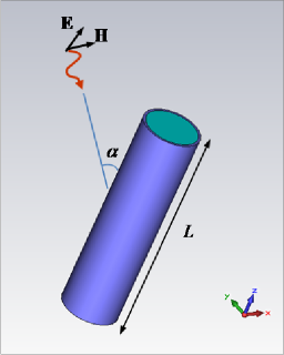
Consider the geometry of Fig. 1, depicting a circular cylinder of finite length , radius , permittivity and permeability , covered by a thin conformal cylindrical cloak shell of thickness , permittivity and permeability . In this section, we examine the limiting case of an infinite circular cylinder () illuminated by an arbitrary plane wave at oblique angle. The general scattering problem may be solved by expanding the impinging and scattered fields in cylindrical harmonics (see e.g. Refs. Balanis1989 ; Bohren1983 ; Yousif1994 ), which we apply to derive the scattering response as a function of incidence angle .
Without loss of generality, the incident wave may be decomposed into its transverse-magnetic (TMz) and transverse-electric (TEz) components, with respect to the cylinder () axis. By matching boundary conditions at the two radial interfaces, the problem may be solved exactly for each cylindrical harmonic Balanis1989 ; Bohren1983 ; Yousif1994 . Analytical results for normal incidence, specifically applied to the cloaking problem at hand, were derived in Ref. Silveirinha2007 . In that special case (), only two tangential field components are non-zero at each interface: for TM polarization, and for TE. This ensures that the scattering problem is easily solved as a set of four equations, and the TE and TM Mie scattering coefficients are easily expressed as a function of determinants, and Silveirinha2007 :
| (1) |
for either TM or TE polarization. We have assumed here and in the following an time dependence. The overall scattering efficiency, defined as the ratio of the total scattering cross section normalized to the cylinder’s physical cross section, is given by Bohren1983 :
| (2) |
As discussed in Silveirinha2007 , by tuning the cloak’s electrical and geometrical properties, the cylinder’s visibility can be minimized by canceling the dominant scattering orders, which is possible under the condition . In the quasi-static limit, i.e., for very thin cylinders, approximate closed-form expressions for these cloaking conditions for TE and TM incidence were reported in Refs. Alu2005b ; Irci2007 .
Scattering for oblique incidence is a more challenging problem, since polarization coupling is usually involved Yousif1994 , as discussed in the Appendix A. This implies that for oblique incidence purely TE or TM cylindrical waves may excite also TM and TE scattered waves, respectively. This feature will play an important role when analyzing the response of the cloak for different incidence angles. In the special circumstance for which this coupling may be absent, or minimized, e.g., as discussed in the Appendix, for azimuthally symmetric modes (), for conducting or high-contrast cylinders, or for small cross-sections, the scattering coefficients may be still expressed as in Eq. (1), where and have generalized expressions:
| (3) |
and
| (4) |
where and are the cylindrical Bessel functions of the first and second kind of order , are their derivatives with respect to the argument, and are the characteristic impedances of each region. The TE expressions may be found by electromagnetic duality: .
These expressions coincide with those in Ref. Silveirinha2007 for normal incidence (), as expected. The dependence on the angle of incidence is encoded in the transverse wavenumbers, . Specifically, , where is the wave number component along the cylinder axis. In particular, , as expected. In the general case, where polarization coupling will occur, Eq. 1 should be modified to include the TM–TE coupling coefficients, consistent with the derivation in the Appendix and the results reported in [36].
II.2 Quasi-Static Analysis
As in the spherical scattering scenario Alu2005a and cylindrical scenario at normal incidence Silveirinha2007 , it is instructive to first consider the case of electrically small cylinders, i.e. . In this limit, as we discuss in the following, the analysis is made simpler by the fact that: (a) the dependence of Eqs. (3,4) on the incidence angle is negligible; consequently, so is the cross-polarization effect on the cloaking conditions; (b) the scattered wave is dominated by a limited number of multipolar orders. The combination of these features makes the plasmonic cloaking easier to achieve, more effective and robust, compared to larger cylinders. This is expected, since satisfying the condition for only few dominant terms in Eq. (2) is easier to achieve, and such conditions are less dependent on the angle of incidence in this regime. In particular, it is easy to show that for regular dielectric cylinders (, ), the dominant terms in Eq. (2) are and , respectively for TM and TE excitations. For arbitrary polarization, scattering dominates. This also applies to a conducting cylinder, whose limiting case corresponds to and in Eqs. (3,4). For a magnetic cylinder (, ) dual considerations apply, so dominates.
II.2.1 Quasi-static cloaking conditions
As discussed in the Appendix, for electrically small cylinders (), the cross-coupling terms vanish for any angular order . We may thus derive the quasi-static cloaking condition by simply taking the first-order Taylor expansion of the coefficients of Eq. (1). This leads to simple closed-form solutions for the appropriate ratio of cloak to core radii to achieve cloaking in the quasi-static limit for each scattering coefficient, consistent with analogous formulas available in the spherical Alu2005a and cylindrical normal-incidence Silveirinha2007 scenarios:
| (5) | ||||
For perfectly electric conducting (PEC) cylinders, a case of particular interest for cloaking applications at radio frequencies, we find:
| (6) | ||||
We note that Ref. Irci2007 misreported that there is no possible quasi-static condition for . The correct formula, shown above, results from taking the proper limits in our previous analysis for and in . This is particularly relevant for oblique incidence, since enforcing only to model a PEC boundary, as suggested in Ref. Irci2007 , would not ensure zero normal component of the magnetic field on the boundary, as required in the PEC limit Sihvola2009 . As correctly reported in Irci2007 , there is no quasi-static condition for the coefficient in the PEC scenario.
A few important points should be highlighted regarding Eqs. (5-6). First of all, Eq. (5) for TE polarization formally coincides with the derivation of Ref. Alu2005a . The formulas here have been obtained for completely generic oblique incidence, generalizing the previously published result. They show that in the long wavelength limit, cloaking conditions are unaffected by an arbitrary variation of the angle of incidence. In this regime, the TM–TE polarization cross terms are of second-order (cf. Appendix A), thus Eq. (5) ensures that an electrically small magnetodielectric cylinder may always be cloaked using its dominant scattering order in the Taylor expansion, regardless of the angle of incidence. As in the spherical scenario, these quasi-static formulas split the role of permittivity and permeability between TM and TE polarizations. Special attention should be paid to the azimuthally symmetric modes, for which the role of permittivity or permeability is reversed compared to higher-order modes. Moreover, again as in the spherical case, the cloaking conditions depend only on the ratio , implying that a thin homogeneous shell may be employed to suppress the relevant scattering orders in this quasi-static scenario. It should be stressed that Eqs. (5-6) may not be met by arbitrary values of the constituent parameters. Rather, they should lie in specific ranges of permittivity, due to the simple physical constraint on geometry .
From a practical standpoint, an electrically thin dielectric cylinder, for which the coefficient is dominant, may always be cloaked by a thin shell with . Under the first of the conditions in Eq. 5, most of the scattering may be suppressed, although significantly negative may be required to achieve a very thin shell. By duality, an electrically thin magnetic cylinder will require .
For such infinite cylinders, the cloaking conditions may in general become trickier than in the spherical case, since the azimuthally symmetric cylindrical waves follow special cloaking conditions: they are permittivity-based for zeroth-order when higher order are permeability-based, and vice versa. This is particularly relevant for the conducting scenario, for which the dominant coefficient may not be canceled at all in the long-wavelength limit (cf. Eq. (6)). It should be emphasized that it is still possible to suppress scattering in the fully dynamic scenario, since it may always be canceled with its dynamic expression . However, in the long-wavelength limit, the required wave number in the cloak considerably grows, implying that quasi-static considerations such as those used in Eq. (6) may not be applied. However, it is evident that conducting objects are significantly more challenging to cloak for cylinders than spheres Alu2007a . The physical reason for this difference is evidently related to the fact that electrically thin cylinders are not electrically small objects. These systems are still infinite in the axial direction (for this analytical treatment), which implies that their scattering may not necessarily be small – above all when conduction currents may be induced in the direction, as with the TM cylindrical wave.
II.2.2 Validation of the quasi-static conditions: Electrically small dielectric cylinder
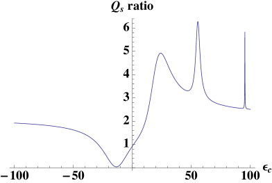
To assess the validity of the previous approximate cloaking conditions in the fully dynamic scattering problem, we present some numerical examples of interest in this section, solved using the exact analytical theory reported above. Consider first the case of a dielectric cylinder with and normalized diameter , covered by a thin uniform cloaking shell with . Fig. 2a shows the variation of the total scattering efficiency as a function of the cloak permittivity and of the angle of incidence of a TM illuminating plane wave. It is immediately apparent that the use of negative-permittivity thin cloaks may significantly reduce the overall scattering efficiency of the cylinder, and in particular minimum scattering is obtained very close to the corresponding quasi-static cloaking condition for in Eq. (5), which would yield . Moreover, minimum scattering is achieved at the same value of negative permittivity, independent of the angle of incidence, consistent with the previous theoretical results, despite some polarization coupling for oblique angles. Overall scattering reduction, compared to no cloak (), is especially significant in the normal incidence case, which provides over 50 dB reduction. For oblique incidence, the coupling with TE coefficients affects the cloaking performance and generates residual scattering at the cloaking condition, but it is seen that the same (negative) value of cloak permittivity may provide significant scattering reduction (over 10 dB) for a wide angular range without drastic changes.
For smaller incidence angles, we also observe excitation of a plasmonic resonance for slightly negative values of . This is associated with the condition , obtained here in the quasi-static limit for , consistent with findings on quasi-static plasmonic resonances in layered spheres and cylinders Alu2005b . It is evident that the resonance is not excited at normal incidence, but arises as soon as oblique incidence is considered, due to cross-polarization coupling. This explains the sharp peak for small negative values of in Fig. 2a. Analogously, for low positive values of , a second small dip in the scattering efficiency appears at , associated with the cloaking condition for = 0 in Eq. (5). Here, this provides the solution . Once again, this dip does not appear at normal incidence, due to the lack of coupling between polarizations for . To conclude this discussion, it should be underlined that, in absolute value, scattering is larger for normal incidence in the uncloaked scenario ( in the figure), as expected, due to the larger component. On the other hand, the proper cloak design may maximally suppress scattering in this worst-case condition, which is an inherent property of this cloaking approach.
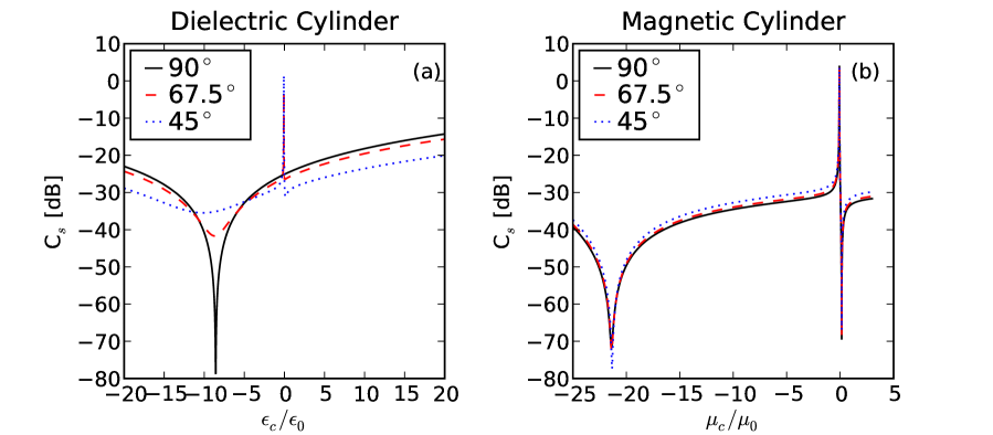
(a) dielectric (, ) and (b) magnetic (, ); for three different angles of incidence of TMz-polarized radiation. In the electrically thin limit, the cloaking conditions have weak dependence on the angle of incidence.
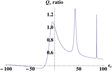
II.2.3 Validation of the quasi-static conditions: Electrically small magnetic cylinder
As a second example, consider the same cylindrical geometry, but with magnetic properties (), again excited by a TMz wave. All other parameters are kept the same. The cylinder’s scattering efficiency is shown in Fig. 2b. As anticipated above, this configuration gives much weaker scattering in the uncloaked scenario (), due to its small size and lack of dielectric contrast with the background. In fact, the coefficient is negligible in this case. Residual scattering is dominated by the higher-order coefficient, which may be canceled with or (note the dual behavior compared to in Fig. 2a). Two clear scattering dips are visible around these two values, which also in this scenario do not depend on the angle of incidence, consistent with Eq. 5. The absence of scattering from higher-order modes and of coupling for the modes ensures that overall cloak performance is unchanged by variations of the incidence angle , as evidenced by the different curves in Fig. 2b.
II.2.4 Quasi-Static Conditions: Conclusions
It should be stressed that the above numerical analyses neglect Ohmic absorption losses in the cloak and/or core materials. We include these effects in the following Sections. Regardless, the plasmonic cloaking technique has been shown to be inherently robust against moderate absorption [20], since it is not based on a resonant effect. This implies that the curves in Fig. 2 would remain practically unchanged near the cloaking regions when moderate losses are considered. On the other hand, the large scattering peaks associated with plasmonic resonances would be significantly dampened by realistic losses. This and the previous considerations imply that:
-
(a)
The plasmonic cloaking technique may be successfully applied to infinite cylinders.
- (b)
-
(c)
Cloaking conditions for electrically thin cylinders are very weakly dependent on .
Thus, cloak designs for electrically thin cylinders are robust against the angle of incidence for any scattering order and polarization. We explore numerically in the following Sections how these properties are affected by considering thicker geometries and truncation effects.
III Plasmonic Cloaking Design and Optimization
For a given infinite cylinder of radius and permittivity , a single-layer plasmonic cloaking shell may be optimized by varying its two design parameters (or ) and , using the analytical results derived in Section II. In general, it is preferable to choose thin shell thicknesses, since drastically increased cross-sections imply reduced bandwidths and larger sensitivities to the design parameters Alu2009b .
This simple cloaking design inherently limits the overall total thickness of cylinders that we may cloak, since only few scattering orders may be drastically suppressed independently. Magnetic properties of the cloak Alu2008b as well as multi-layer designs Alu2008e may be considered to increase the available degrees of freedom and size of objects to be cloaked. In this work, however, for sake of simplicity we limit our interest to non-magnetic cloaks, and we consider moderate cross-sections of the objects to be cloaked. In particular, in the following we consider cylinders with diameters and relative permittivities of 3 and 10 in the dielectric scenario, in addition to a PEC cylinder. Since the previous theoretical discussion shows that infinite cylinders may be effectively cloaked, as anticipated, we consider overall lengths L of several times the diameter, which may be comparable to or larger than the wavelength of operation.
Because of the TM–TE polarization coupling described in the previous Section (cf. also the Appendix A), completely general cloak optimization would be quite complicated, and in general depend on the incidence angle and polarization of excitation. We choose instead to optimize cloak response at normal incidence – which is usually the angle for which larger scattering is produced – then examine the response at oblique angles with numerical simulations. More extensive cloak optimization would involve the choice of a cost function and the application of global (e.g. genetic algorithms Kerkhoff2009 ) and local (e.g. Quasi-Newton) optimization techniques across all angles and polarizations, also as a function of the observer’s position. In general, further optimization may be achieved by considering magnetic cloaks, as discussed above. We will analyze these aspects in the near future.
III.1 Design Parameter Space: the View from Above
To provide insight into the effects of the various parameters involved in cloak design, we examine the variation of scattering efficiency with and for TE or TM plane wave normal incidence in the infinite (2D) scenario, using the formulation developed in the previous Section. To that end we write the scattering gain as:
| (7) |
is the scattering efficiency from Eq. (2), and the superscript represents the uncloaked case, calculated with Eqs. (1-4), in the limit and .
In general, the above discussions show that it is not possible to achieve large scattering reduction for both TM and TE illumination simultaneously with a single-layer permittivity cloak at the same frequency. For moderate cross-sections, however, such as those considered here, scattering is generally dominated by one of the two responses. It is thus best to design for maximal suppression of that polarization. Hence, we focus on TMz waves, which dominate scattering from infinite dielectric and conducting cylinders in the long wavelength limit (cf. quasi-static analysis in the previous Section). Ideally, the cloak is designed to provide minimized scattering gain for normal incidence.
For our calculations we used Mathematica Mathematica and truncated the Mie summations at order , which ensured convergence for the cross-sections considered here. Fig. 3 shows scattering gain contour plots for infinite cylinders of diameter , relative permittivities (Fig. 3a) and (Fig. 3b), and TM normal incidence. The plots show alternating loci of resonant peaks (large , light color) and cloaking regions (near-zero , dark color). As expected, thinner cloaks (smaller ) yield larger bandwidths, reflected by wider cloaking regions. This implies that the ideal cloak design would utilize , as expected from the results in Sec. II, from simple physical considerations and analogous results in the spherical scenario Alu2005a . The cloaking loci for large positive values of are associated with anti-resonances that arise when the shell thickness is comparable to the wavelength in the shell material. These anti-resonances are narrow-bandwidth and highly sensitive to the design parameters, and they necessarily lie in close proximity with scattering resonant peaks, which makes them not suitable for a robust cloaking design. Fig. 4 shows constant slices of Fig. 3 to better illustrate these characteristics. These slices illustrate how choices typically produce lower scattering gain, i.e. better cloaking, away from dangerous resonant enhancements. This is especially true when cloaking low-density dielectric cylinders.
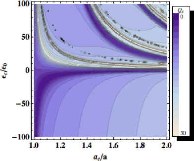
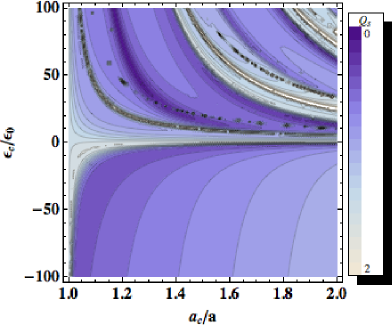
(a) (b)
We also considered optimization of plasmonic cloaks for PEC cylinders of the same size. However, as noted in the quasi-static limit, here the dominant scattering contribution (via the coefficient), may not be canceled in the long-wavelength regime. This implies that in the corresponding contour plots there would not be cloaking regions for thin negative-permittivity shells, as in the dielectric scenario. Moderate scattering reduction may be achieved with large- thick shells, but as outlined above this implies large sensitivity to frequency, design variations and closely-spaced resonant peaks, which may be excited at different incidence angles. It is thus evident that a simple permittivity cloak may not be sufficient to adequately cloak a PEC cylinder and, as in the spherical scenario Alu2005a , it may require magnetic permeability different from the background for robust scattering reduction. In the following, therefore, we mainly focus our design efforts on dielectric cylinders.
III.2 Cloak Design
The previous results show that optimal cloak configurations for dielectric cylinders are based on negative permittivity metamaterials and thin cloak shells. We should point out that negative values of effective permittivity may indeed be achieved in the microwave or THz frequency ranges using various metamaterial geometries, such as wire media or parallel-plate implants Silveirinha2007 , and they are naturally available at larger frequencies. In particular, the parallel-plate implant technology may be particularly well-suited for cloaking incident TMz waves, as it has been already demonstrated theoretically and verified experimentally for normal incidence at microwave frequencies Silveirinha2007 ; Edwards2009 . We assume here, for sake of simplicity, that the required value of effective permittivity is available for the shell geometry of interest and that the cloak material is isotropic. Possible anisotropy for a specific metamaterial realization, inherent in some proposed realizations Silveirinha2007 ; Edwards2009 , may affect cloak performance for different incidence angles, but our preliminary results show that for thin cloaks such effects may be minor. Thus, for simplicity we always assume idealized isotropic metamaterials in the following. The requirement that any passive metamaterial has a frequency dispersion ensuring is met here by assuming a Drude dispersion model of the form:
| (8) |
Here and in the numerical simulations in the next Section, we calculated the plasma frequency to ensure that at the design frequency the real part of yields the required value. The damping frequency , associated with the level of losses in the metamaterial, has been always assumed in the following to be . This value provides a moderate amount of loss, comparable with practically-realizable metamaterial geometries at these frequencies.
Table 1 summarizes an extensive campaign of optimizations that we performed to cloak different cylindrical geometries, as outlined above, considering several cloaking designs. Inspecting Table I, we see that thin cylinders (), consistent with the previous quasi-static analysis, require optimized cloaks with negative permittivity in the case of dielectric objects, and a large positive permittivity for conducting materials. The corresponding scattering gain may become extremely low, since only few Mie coefficients effectively contribute to the total scattering, and they are properly canceled by the optimized cloak design. As a general rule of thumb, consistent with the previous considerations, thinner cloaks require larger values of permittivity, either positive or negative. Relatively thicker cloaks relax the requirements on very negative permittivity of the cloak, but, as highlighted above, larger thickness also tends to produce additional scattering terms, which limits overall performance. However, lower absolute values of negative (in the case of dielectric) or positive (for PEC) permittivity may be easier to achieve and be less sensitive to loss. A trade-off between cloak thickness, material reliability and overall cloaking performance should be considered. Larger dielectric objects may be cloaked by thicker cloaks with positive values of permittivity, since the dynamic nature of the wave in the cloak may produce a negative polarizability even with positive materials in larger shells. However, the overall scattering reduction is less dramatic; residual scattering is indeed expected for larger objects. In particular, as discussed above, conducting cylinders are most challenging to be cloaked against TM waves, due to the axial conduction currents induced on their surface. Scattering reduction of around 3 dB, however, may still be achieved even for conducting cylinders. Moreover, large values of core permittivity are harder to cloak, and the residual scattering is larger than for a lower-permittivity core of the same size.
Our cloak designs in Table 1 were optimized for TM normal incidence, the scenario with maximum scattering for the considered objects. At oblique incidence, however, TM–TE coupling excites additional scattering modes, which may affect the overall response, in particular for thicker objects and moving toward grazing incidence. We discuss these features in detail in the next Section.
| Core diam. () | Core | Cloak | Cloak | |
|---|---|---|---|---|
| 3 | 1.10 | -8.16 | 0.26 | |
| 3 | 1.40 | 22.45 | 0.13 | |
| 10 | 1.05 | 13.37 | 0.22 | |
| 10 | 1.10 | 6.91 | 0.22 | |
| PEC | 1.10 | 95.48 | 0.47 | |
| 3 | 1.05 | -27.88 | 0.031 | |
| 3 | 1.10 | -13.55 | 0.038 | |
| 10 | 1.10 | -35.00 | 0.36 | |
| 10 | 1.20 | 74.57 | 0.16 | |
| PEC | 1.50 | 14.01 | 0.37 | |
| 3 | 1.05 | -20.26 | 0.00076 | |
| 3 | 1.10 | -9.45 | 0.00092 | |
| 10 | 1.10 | -56.25 | 0.0017 | |
| 10 | 1.30 | -17.87 | 0.0034 | |
| PEC | 1.40 | 88.92 | 0.096 |
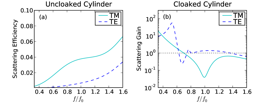
Fig. 5 considers the typical frequency dependence of cloak performance on wave polarization. The left panel shows the uncloaked scattering widths for an infinite dielectric cylinder with and for TM and TE normally-incident plane waves. As expected, the TM polarization is more strongly scattered, thus it is of more relevance in designing an optimized cloak. However, despite the much smaller response to TE waves, it is interesting to analyze the behavior of a TM-optimized cloak to TE polarization, since a portion of the TM scattered power may be coupled to TE waves for TM oblique incidence, in particular for smaller incidence angles. The right panel shows the normalized scattering gain for TM and TE incidence, considering a conformal shell cloak with and at design frequency with Drude dispersion, which coincides with the optimized design at for TM normal incidence. We see how the cloak is very effective over a relatively broad range of frequencies around for TM incidence, despite the natural dispersion of the cloak material. However, this same cloak does not provide scattering reduction at the same frequency for impinging TE waves, supporting instead a small cloaking dip at lower frequencies. Although this per se is not a major issue, since the absolute value of the TE scattering is much smaller (left panel), and the quantities in the right panel are normalized to the corresponding uncloaked scattering, this issue may cause an overall dependence of the cloaking response to the incidence angle for TM excitation, due to the TM-TE polarization coupling. We verify these issues in the next Section, which considers the performance of finite-length cylinders illuminated at oblique incidence.
IV Numerical Results for Finite-Length Cylinders and Oblique Incidence
After having considered the optimization of cloaks for dielectric and conducting infinite cylinders, we consider in this Section the effects of finite length and varying angle of incidence on the performance of cylindrical plasmonic cloaks, using full-wave numerical simulations CST . To keep the design simple, in our numerical simulations we simply truncated the cloaked cylinder, as optimized in the previous section, consistent with the geometry in Fig. 1, leaving the ends uncovered. This is expected to cause additional scattering, especially for more oblique incidence (smaller ). However, since this cloaking technique is based on an integral effect Alu2007a , for moderate cross-sections these effects are not expected to significantly deteriorate the overall cloaking performance. This intuition is confirmed by the following numerical results. Improved performance may be obtained by locally tailoring the cloak around the edges, and covering the ends, as described for conical geometries in Tricarico2010 . The small improvements achievable with this fine-tuning of the cloak design are in any case not relevant to the following general discussion.
IV.1 Dielectric Cylinder at Normal Incidence
Consider first the dielectric cylinder of Fig. 2a (, , diameter cm), but with finite length cm. Our objective is to reduce its scattering cross-section at the design frequency GHz, for which this object has cross-sectional width and length ; cm is the free-space wavelength at frequency . In this frequency range, the object may produce significant scattering, since its length and electrical size are comparable to the incident wavelength. Scattering at normal incidence is dominated by the TMz polarization (cf. Sec. II), so we excite the cylinder with an impinging TM wave, and use a cloak with permittivity ( GHz) at and thickness , obtained in Sec. III. Note the relatively large negative permittivity required by such thin layer. For a thicker cloak, may be reduced, but at the price of possible excitation of higher-order cylindrical harmonics, which may slightly deteriorate the cloak performance.
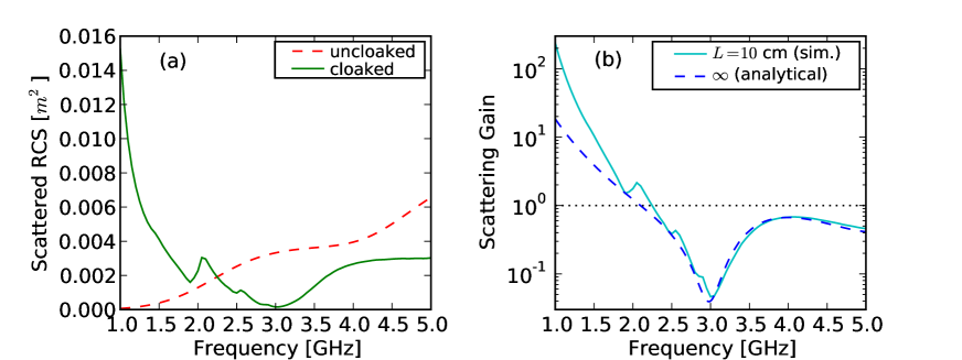
Fig. 6a plots the total 3D radar cross section (RCS) Balanis1989 , obtained by integrating the scattering cross section over all angles, calculated using commercial software based on the finite-integration technique CST . It compares the cloaked (solid green curve) and uncloaked (red dashed curve) scenarios for normal incidence (). Despite the cylinder’s finite electrical length and its non-negligible cross-section, scattering at the design frequency may be significantly suppressed with a proper cloak design. As expected, the scattering is a minimum at , and the bandwidth of operation is moderately large, as is common for plasmonic cloaks Alu2007a . Significant scattering reduction is achieved over a fractional bandwidth of over . Fig. 6b plots the corresponding scattering gain, defined as the ratio between the total RCS of the cloaked and uncloaked geometries. The curves effectively show the overall scattering reduction achieved by adding the cloak to the bare cylinder for different frequencies. The plot compares the full-wave simulations for finite-length cylinders calculated using CST , with the infinite-cylinder analytical formulation derived in the previous section. The overall scattering reduction is dB at , and the analytical result for an infinite cylinder agrees extremely well with the full-wave simulation for a finite cylinder, despite the truncation effects. At lower frequencies, GHz, the plasmonic nature of the cloak and its negative permittivity induces a plasmonic wave along the cylinder, which actually increases the overall scattering compared to the uncloaked scenario. This is predicted in both the infinite and finite-length cases, and readily observed in Fig. 6b. There, the contribution is even stronger for the finite-length truncated cylinder, due to plasmonic radiation at the ends.
Table 2 summarizes the calculated overall suppression at for the dielectric-core cloak designs of Table 1 illuminated by TM waves at normal incidence. In particular, the table compares the simulated scattering gain for finite lengths with the theoretical value predicted analytically for infinite cylinders . We observe excellent agreement between predicted results from the analytical formulas for the infinite cylinder, and full-wave numerical simulations for the truncated geometries. This implies that truncation effects are not significant in several realistic setups when cloaking dielectric cylinders with the plasmonic cloaking technique.
| Core diam. () | Core | Cloak | |||
|---|---|---|---|---|---|
| 2 | 3 | -8.16 | 0.17 | 0.27 | |
| 4 | 3 | -13.55 | 0.038 | 0.046 | |
| 4 | 10 | -35.00 | 0.17 | 0.38 | |
| 4 | 3 | -9.45 | 0.0049 | 0.042 |
IV.2 Varying Angle of Incidence
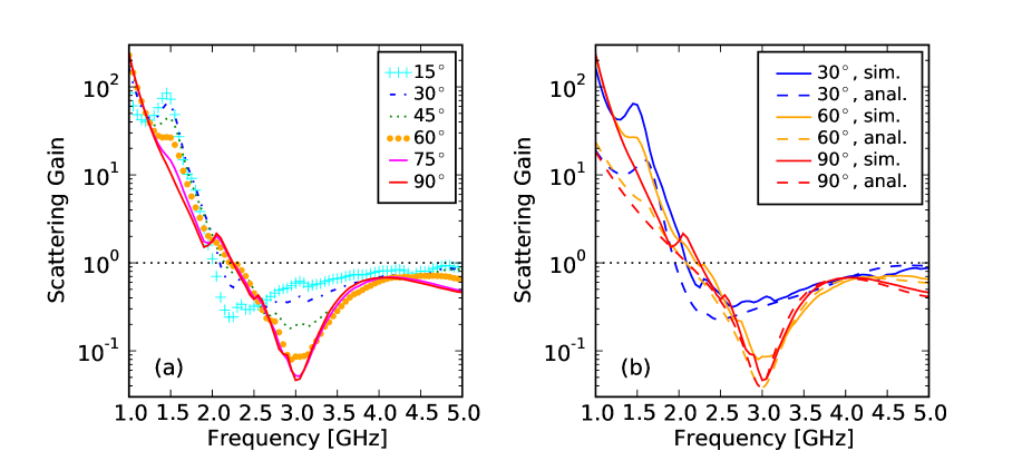
Fig. 7 shows the variation of scattering gain for the cylinder of Fig. 6 varying the incidence angle , as depicted in Fig. 1. Even for small (near grazing) incidence angles, the cloaking effects are barely different from the normal-incidence case. For smaller values of , cloaking is somewhat reduced at , due to the excitation of TE scattered waves via cross-polarization coupling, as discussed in Sec. II. These results demonstrate strong agreement between the analytical calculations for infinite cylinders and the numerical simulations for finite , although some expected minor deviation does appear at small angles, due to end effects. We emphasized that, although the normalized scattering gain is reduced less for smaller angles, the overall RCS is significantly smaller in these cases, since the electric field component along the cylinder is comparatively shorter, consistent with the discussion in the previous Section. The results of Fig. 7 demonstrate convincingly that plasmonic cloaking may be applied to finite-length dielectric cylinders at oblique excitation, although at small one may be required to cloak the TE contribution separately for improved performance. This is consistent with our findings in Fig. 5.
IV.3 Varying Diameter
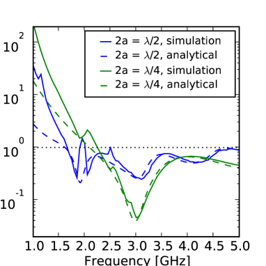
The left panel of Fig. 8 shows the scattering gain under normal-incidence TMz illumination for the cylinder of Sec. IV.1 (cf. Fig. 6) next to that for a cylinder with twice that diameter, (cf. Table 1 for cloak parameters). The figure also compares these results with the infinite-cylinder analytical result of Sec. II. End effects are negligible except at low , and the analytical results match very well the numerical simulations – especially at frequencies where plasmonic resonances are not excited. Cloaking is effective over a relatively broad bandwidth, even for the thicker cylinder. This implies that the designed cloaks may be effective over a relatively broad range of object size. The excellent agreement between the analytical curves for infinite cylinders and the simulation results for truncated geometries indicate that truncation effects are negligible for cloaking performance and suggest the use of the previously derived analytical formulas for fast cloak optimization. A simple permittivity cloak, as considered here, is effective for significant scattering reduction for cylinders with diameters of the order of the wavelength. Thicker cylinders may require the use of multilayer and/or magnetic cloaks, as discussed in Ref. Alu2008b for spherical geometries.
IV.4 Varying Object Permittivity
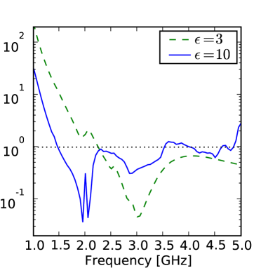
The right panel of Fig. 8 shows the scattering gain for the cylinder of Sec. IV.1 (cf. Fig. 6), for the same dielectric and also with a denser core, (see Table 1). In the large- limit, this comparison underscores some of the challenges that may be involved in cloaking a conducting object, which would coincide with a dielectric core in the limit of very large permittivity. There is significant scattering reduction around the design frequency also in the denser scenario, but this example simultaneously supports even stronger cloaking at a lower frequencies, GHz. This effect, predicted by the analytical results for infinite cylinders, is associated with the frequency dispersion of the cloak, which matches the cloaking condition for the coefficient at lower frequencies (for more negative values). Effectively, this scenario presents a coincidental cloaking effect at another frequency. This does not imply that one could tune the second suppression arbitrarily, since its position depends on the natural metamaterial dispersion. However, one could tune its separation from to a limited degree if the cloak thickness were not fixed at .
IV.5 Varying Cylinder Length
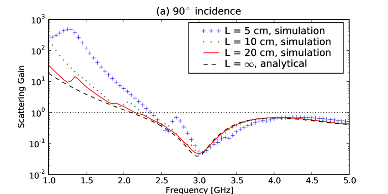
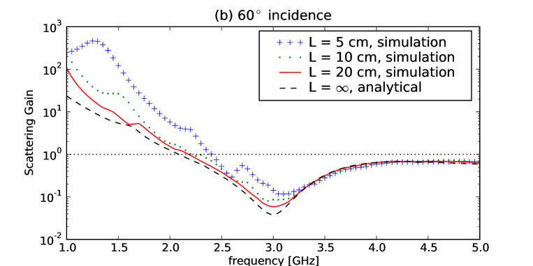
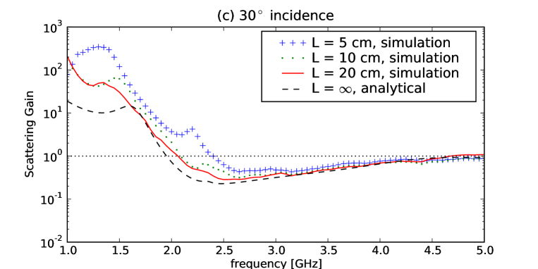
Fig. 9 analyzes in more detail the effects of truncation for the case of Fig. 6 in Sec. IV.1, by considering different truncation lengths for several incidence angles: for the three panels, respectively. Each compares different lengths, including the analytical result for infinite cylinders. The cloaking effect is indeed robust against variations in incidence angle, and truncation effects are quite moderate, as the scattering gain follows the line calculated analytically in the infinite cylinder geometry. Even for the shortest length ( cm, a 2:1 aspect ratio), the full-wave simulation still follows the infinite-length case with surprising accuracy, above all near . In this case, scattering is characterized by small resonant peaks at lower frequencies, associated with longitudinal resonances due to the finite length. The results are nevertheless extremely encouraging, in particular for shorter cylinders, for which the cloaking design works extremely well in the frequency range of interest.
IV.6 Near- and Far-Field Plots
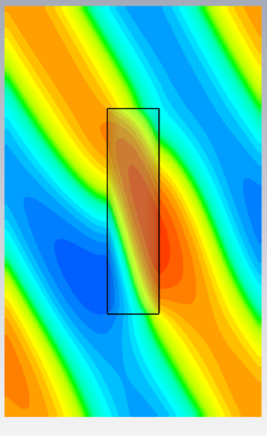
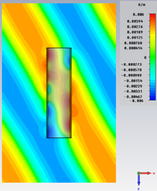
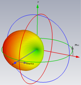
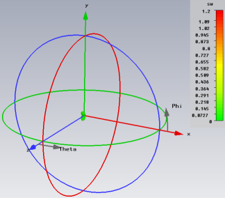
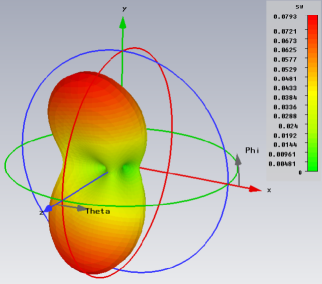
Figs. 10-11 illustrate the full-wave near- and far-field numerical results for the cylinder of Sec. IV.1 (Fig. 6), illuminated by a TM wave impinging at an angle . The various figures compare in panel (b) the cloaked configuration at the design frequency with the uncloaked case (a). Consistent with Fig. 2a, the overall calculated RCS reduction at the central frequency is -14.2 dB, and the following figures depict the effective functionality of the cloak in its near- and far-field regions. We have chosen to indicate the performance of the cloak to oblique excitation; similar considerations apply for any other angle of incidence, which we have verified via detailed study.
Fig. 10 shows the (normal) magnetic field distribution on the E plane (snapshot in time), comparing the uncloaked scenario (a) with the cloaked one (b). Several interesting features are noteworthy. In the uncloaked case, the wave penetrates the dielectric rod and experiences a wavelength shortening that effectively distorts the planar wave fronts on the back of the cylinder, producing significant shadow and scattered fields all around the object. The thin plasmonic metamaterial shell is able to re-establish the proper planar fronts just outside the cloak (b), ensuring reduced scattering and suppressed visibility for an outside observer positioned anywhere in the near- or far-field of the object. It should be noted that this effect is obtained for oblique incidence, and the cylinder ends are uncloaked. Additional improvement may be achieved by proper cloaking of these terminations. We may also easily observe how the plasmonic layer supports surface-plasmon waves traveling along the shell, as expected due to its negative permittivity. It is interesting to observe how these waves effectively cancel the residual scattering and restore the phase fronts to almost exactly match those of the original plane wave, had it traveled through free space instead.
Fig. 11 illustrates the far-field radiation patterns for this same cylinder, comparing on the same scale scattering from the uncloaked (a) and cloaked (b) objects, showing drastic suppression of the bistatic RCS at all angles. Uncloaked scattering exhibits itself mainly as a shadow on the cylinder backside; various higher-order scattering harmonics contribute to this residual scattering pattern. Most of the scattering is suppressed by the cloak. Panel (c) shows the cloaked residual scattering on a much smaller scale: as expected, scattering is not identically zero, and small lobes, associated with higher-order (and more directive) cylindrical harmonics not completely suppressed, are still present. Their relevance, however, is very limited compared to the original scattering levels.
(a) uncloaked cylinder
(b) cloaked cylinder
(a) uncloaked cylinder
(b) cloaked cylinder
(c) cloaked cylinder (zoomed in)
V Conclusions
We have presented an extensive investigation of the application of the plasmonic cloaking technique to circular cylinders illuminated by plane waves of arbitrary polarization and angle of incidence. We have derived analytical formulas for the general oblique-angle scenario, and showed that in the electrically-thin limit there is no angular dependence on the cloaking response, i.e. the design formulas are independent on the angle of incidence.
To study the characteristics of cylindrical cloaks, we have designed a set of TMz-optimized cloaks for a wide range of parameters and cylinders of interest, using the normal-incidence analytical formulas with realistic losses and metamaterial frequency dispersion implemented in a Drude model. For the cloak design, we have focused on TM polarization because it dominates the scattering of moderately thick dielectric and conducting cylinders, which is of interest for several applications within the radar community. The optimized cloaks’ drastic scattering reduction was corroborated with full-wave numerical simulation, taking into account variations of the angle of incidence, core permittivity, cylinder diameter, and most importantly truncation effects due to finite length.
We have found that, as predicted by the analytical formulas presented here, for elongated objects with diameters up to one-half the wavelength (for which our cloaking technique is most effective), but with length comparable with the wavelength of operation, a simple one-layer permittivity cloak is very effective, providing significant scattering reduction highly robust to variations in the angle of incidence. Performance is slightly weakened at near-grazing angles, for which TM–TE polarization coupling partially affects the overall performance of a single-layer cloak optimized for TM polarization alone. We note, however, that scattering approaching grazing angles is the weakest in absolute value, thus less important for achieving overall scattering reduction.
The analytical theory developed here for infinite cylinders has been strongly corroborated by our numerical simulations for finite lengths, implying that the truncation effects do not significantly perturb the cloaking effect. We are currently working on the extension of these concepts to multi-layered metamaterial cloaks for suppression of multiple scattering coefficients, and contemporary suppression of TE and TM scattered waves, which may increase the size of the cloaked objects and the angular range of operation. We are also currently pursuing an experimental realization of the plasmonic cloaking concept at radio frequencies for practical finite cylinders and cloaks.
*
Appendix A Analytical Solution of the Scattering from a Two-Layer Circular Cylinder for Oblique Incidence
Consider the geometry of Fig. 1, consisting of a circular cylinder of radius , permittivity and permeability , covered by a thin conformal cylindrical cloak shell of thickness , permittivity and permeability . When excited by an impinging infinite plane wave of arbitrary incidence angle and polarization, the general scattering problem may be solved in the limit of long cylinders () by expanding the impinging and scattered fields in terms of cylindrical harmonics Balanis1989 ; Bohren1983 ; Yousif1994 . The problem may be split into the orthogonal polarizations with -field transverse to the cylinder axis (TEz) and -field transverse (TMz).
For a TMz plane wave impinging at an angle from the cylinder axis , the incoming magnetic field may be written as:
| (9) |
where is the electric field amplitude, and are the free-space characteristic impedance and wave number, is the wave number component along the cylinder axis, is the transverse component of the wave number, and the corresponding impinging electric field may be calculated using the curl Maxwell’s equations. Expanding in cylindrical waves, we may write electric and magnetic fields as:
| (10) |
where
| (11) |
and is the cylindrical Bessel function of order . Analogous expressions for TEz waves may be derived using duality.
Using the orthogonality of cylindrical waves, the boundary conditions at the radial interfaces may be met by assuming the existence of transmitted cylindrical waves in the two dielectric regions and a scattered wave in free-space, which may be written consistently with Eq. (10), using the scalar potentials:
| (12) | |||||
for the fields induced in the core region, shell, and for the the scattered field, respectively. The core and cloak regions are labeled “1” and “2”, respectively, and “s” represents the scattered wave outside the cloak; are the relevant transverse wave numbers for each region and . and are the cylindrical Bessel functions of the first and second kind, for incoming and outgoing waves, while is the cylindrical Hankel function. The complex scattering coefficients are the unknowns. Analogous equations may be written for TEz waves.
For normal incidence (), for PEC objects, or for the azimuthally symmetric mode , the problem is easily solved by matching the two non-zero tangential field components at each radial interface:
| (13) |
for TMz(TEz) polarization. This yields the familiar rank-four determinant expressions reported in Eqs. (3,4). Consistent expressions for the TEz coefficients may be obtained by applying duality. In the general case of oblique incidence on a dielectric cylinder, however, the higher-order modes are characterized by all four independent tangential components of the fields at each interface, which may not be matched independently for each TEz or TMz harmonic. The boundary conditions may instead be met, as derived in Yousif1994 , by linearly combining TEz and TMz harmonics of same order . The corresponding solution of an eight-by-eight system of equations, derived in Yousif1994 , provides the exact expression of the scattering coefficients in the general case, to be used in Eq.( 2) to derive the total scattering width of the cylinder. This form of polarization coupling is inherently associated with the asymmetry introduced by the oblique excitation for higher-order modes, and it may be avoided only in the case of conducting objects or for . In the quasi-static limit, however, the dependence of the arguments of the Bessel functions in Eqs. 12 on the transverse wave number is negligible as well; therefore this form of cross-polarization coupling is negligible. In this limit, Eqs. (3-4) may be used for any angle of incidence, at the basis of the derivation of Eqs. (5-6), which do not depend on .
Acknowledgements.
A. A. was partially supported by the National Science Foundation (NSF) CAREER award ECCS-0953311. A. K. and D. R. were supported by an internal research award at ARL:UT.References
- (1) J.B. Pendry, D. Schurig and D.R. Smith, Science 312, 1780 (2006).
- (2) D. Schurig et al., Science 314, 977 (2006).
- (3) W. Cai, U.K. Chettiar, A.V. Kildishev and V.M. Shalaev, Nature Photonics 1, 224 (2007).
- (4) U. Leonhardt, Science 312, 1777 (2006).
- (5) G.W. Milton, N.A. Nicorovici, R.C. McPhedran and V.A. Podolskiy, Proc. Roy. Soc. Lond. 461, 3999 (2005).
- (6) G.W. Milton and N.A. Nicorovici, Proc. Roy. Soc. Lond. A: math. Phys. Sci. 461, 3027 (2006).
- (7) A. Greenleaf, Y. Kurylev, M. Lassas and G. Uhlmann, Comm. in Math. Phys. 275, 749 (2007).
- (8) D.A.B. Miller, Opt. Expr. 14, 12457 (2006).
- (9) A. Yaghjian and S. Maci, New Journal of Physics 10, 115022 (2008).
- (10) P. Alitalo et al., IEEE Trans. Antennas Propagat. 56, 416 (2008).
- (11) S. Tretyakov, P. Alitalo, O. Luukkonen and C. Simovski, Phys. Rev. Lett. 103, 103905 (2009).
- (12) G. Castaldi et al., Opt. Expr. 17, 3101 (2009).
- (13) Y. Lai et al., Phys. Rev. Lett. 102, 253902 (2009).
- (14) Y. Lai et al., Phys. Rev. Lett. 102, 093901 (2009).
- (15) A. Alù and N. Engheta, Phys. Rev. E 72, 016623 (2005).
- (16) P. Alitalo and S.A. Tretyakov, Mat. Today 12, 212 (2009).
- (17) A. Alù and N. Engheta, J. Opt. A 10, 093002 (2008).
- (18) M. Kerker, J. Opt. Soc. Am. 65, 376 (1975).
- (19) A. Alù and N. Engheta, Phys. Rev. E 78, 045602 (2008).
- (20) A. Alù and N. Engheta, Optics Express 15, 3318 (2007).
- (21) A. Alù and N. Engheta, Radio Science 43, RS4S01 (2008).
- (22) A. Alù and N. Engheta, Electromagnetics 28, 464 (2008).
- (23) A. Alù and N. Engheta, Optics Express 15, 7578 (2007).
- (24) A. Alù and N. Engheta, Phys. Rev. Lett. 100, 113901 (2008).
- (25) A. Alù and N. Engheta, New J. Phys. 10, 115036 (2008).
- (26) A. Alù and N. Engheta, Phys. Rev. Lett. 102, 233901 (2009).
- (27) A. Alù, Phys. Rev. B 80, 245115 (2009).
- (28) S. Tricarico, F. Bilotti, A. Alù and L. Vegni, Phys. Rev. E 81, 026602 (2010).
- (29) E. Irci and V.B. Ertürk, Phys. Rev. E 76, 056603 (2007).
- (30) E. Irci, “Wave propagation in metamaterial structures and retrieval of homogenization parameters”, M.§. Thesis, 2007.
- (31) H. Wang and X. Zhang, J. Appl. Phys. 106, 053302 (2009).
- (32) M.G. Silveirinha, A. Alù and N. Engheta, Phys. Rev. E 75, 036603 (2007).
- (33) B. Edwards, A. Alù, M.G. Silveirinha and N. Engheta, Phys. Rev. Lett. 103, 153901 (2009).
- (34) F. Bilotti, S. Tricarico and L. Vegni, New Journal of Physics 10, 115035 (2008).
- (35) F. Bilotti, S. Tricarico and L. Vegni, IEEE Trans. Nanotecnol. 9, 55 (2010).
- (36) C.A. Balanis, Advanced Engineering Electromagnetics (Wiley, New York, 1989).
- (37) C.F. Bohren and D.R. Huffman, Absorption and Scattering of Light by Small Particles (Wiley, New York, 1983).
- (38) H.A. Yousif, R.E. Mattis and K. Kozminski, Appl. Opt. 33, 4013 (1994).
- (39) A. Alù and N. Engheta, J. Appl. Phys. 97, 094310 (2005).
- (40) A. Sihvola, H. Wallen, and I.V. Lindell, Dig. Metamaterials Conference, London, UK (2009).
- (41) A. Kerkhoff and H. Ling, Radio Sci. 44, RS6006 (2009).
- (42) Mathematica 7, http://www.wolfram.com/mathematica.
- (43) CST Design Studio 2009, http://www.cst.com.