11email: mmocak@ulb.ac.be 22institutetext: Max-Planck-Institut für Astrophysik, Postfach 1312, 85741 Garching, Germany
22email: ewald@mpa-garching.mpg.de
Rayleigh-Taylor finger instability mixing in hydrodynamic shell convection models
Abstract
Context. Mixing processes in stars driven by composition gradients as a result of the Rayleigh-Taylor instability are not anticipated. They are supported only by hydrodynamic studies of stellar convection. We find that such mixing occurs below the bottom edge of convection zones in our multidimensional hydrodynamic shell convection models. It operates at interfaces created by off-center nuclear burning, where less dense gas with higher mean molecular weight is located above denser gas with a lower mean molecular weight.
Aims. We discuss the mixing under various conditions with hydrodynamic convection models based on stellar evolutionary calculations of the core helium flash in a 1.25 M⊙ star, the core carbon flash in a 9.3 M⊙ star, and of oxygen burning shell in a star with a mass of 23 M⊙ .
Methods. We simulate the hydrodynamic behavior of shell convection during various phases of stellar evolution with the Eulerian hydrodynamics code HERAKLES in two and three spatial dimensions. Initial models for this purpose are obtained by state-of-the-art stellar evolutionary codes, namely GARSTEC, STAREVOL, and TYCHO for the core helium flash, core carbon flash, and oxygen shell burning, respectively. Most of our analysis is performed for two-dimensional hydrodynamic models of shell convection during the core helium flash at its peak covering approximately 250 convective turnover timescales or 1.4 days of stellar evolution.
Results. The mixing manifests itself in the form of overdense and cold fingers enriched with matter of higher mean molecular weight, originating from density fluctuations at the lower boundary of the convective shell, and “shooting” down into the core. The fingers are neither produced by overshooting from the convection zone nor by thermohaline mixing. Instead, they result from the Rayleigh-Taylor instability at the lower convection zone boundary due to a negative mean molecular weight gradient (molecular weight decreasing in the direction of gravity). They do not appear when the mean molecular weight gradient is positive. We call this process Rayleigh-Taylor finger instability mixing or RTFI mixing for short.
Key Words.:
Stars: evolution – hydrodynamics – convection – mixing1 Introduction
The hydrodynamic approach to model certain phases of stellar evolution, like e.g., a nuclear core flash, by numerically solving the Euler or Navier-Stokes equations is essentially built upon first principles in physics, and thus (almost) parameter-free. This approach is advantageous compared to (1D) stellar evolutionary calculations when modelling phenomena related to flow instabilities which are inherently multidimensional in nature. One of these instabilities is the Rayleigh-Taylor (RT) instability (Rayleigh 1883; Taylor 1949), caused by the buoyancy force which acts on fluid/gas elements (blobs) of matter that are over-dense or over-light with respect to the matter surrounding them.
One consequence of the RT instability in stellar evolution is the occurrence of convection (Kippenhahn & Weigert 1990; Weiss et al. 2004), whose role for stellar evolution is even nowadays still mainly known from 1D hydrostatic stellar evolutionary calculations. However, convection is a genuine multidimensional phenomenon, i.e., its properties can be reliably inferred only on the basis of multidimensional hydrodynamic simulations. To this end several hydrodynamic studies of shell convection in the cores of stars (hence sometimes called core convection) have been performed in recent years studies, with interesting conclusions (Deupree 1996; Dearborn et al. 2006; Herwig et al. 2006; Meakin & Arnett 2007; Mocák et al. 2009). These simulations also considered the effects of composition gradients, but without investigating their influence in much detail, except for the work of Meakin & Arnett (2007) highlighting the importance of turbulent entrainment (Fernando 1991) at the boundaries of convection zones.
Composition gradients play an important role during the evolution of stars of all masses. They can instigate double-diffusive instabilities (Kippenhahn et al. 1980; Turner 1985) i.e., “salt-fingering” or the occurrence of vibrational overstability known as semi-convection (Grossman & Taam 1996, ;and references therein) and can trigger gravitational settling (Stancliffe & Glebbeek 2008) thereby influence the evolution of a star. Chemical gradients are also likely responsible that a star becomes a red giant (Stancliffe et al. 2009), and they lead to deep mixing in envelopes of low-mass red giants (Eggleton et al. 2006).
Stellar layers with a negative mean molecular weight gradient (i.e., the molecular weight decreases in the direction of gravity) can develop a shell where thermohaline mixing occurs (Kippenhahn et al. 1980), which is driven by a double-diffusive instability. Thermohaline mixing can be regarded as a diffusion process where blobs of gas with higher molecular weight sink down, while other material rises and mixes with neighboring gas, eventually providing further rising and sinking elements. Such a situation is encountered, e.g., during the off-center ignition of helium in the helium core during the core helium flash, where a convective shell forms above the ignition point which is continuously enriched by nuclear ashes with a higher molecular weight (mainly 12C). This creates a negative mean molecular weight gradient at the base of the convection zone, which should cause thermohaline mixing within a thermal timescale (Kippenhahn et al. 1980). Thermohaline mixing is supposed to manifest itself in the form of finger-like structures (Turner 1985), which are indeed observed, e.g., in oceanography Williams (1974); Gargett & Schmitt (1982). On the other hand, results from experimental chemo-hydrodynamics often reveal instabilities that have a finger-like structure as well, but which are not regarded as thermohaline mixing. Well known in this context (De Wit 2004, 2008) is viscous fingering where a less viscous fluid is displacing a more viscous one in porous media (Saffamn-Taylor instability), and density fingering driven by a Rayleigh-Taylor instability in systems, where a denser solution resides above a lighter one.
In the following we discuss a mixing process characterized by sinking dense blobs of gas that carry matter of higher mean molecular weight rapidly and presumably adiabatically downwards (in the direction of gravity) into matter of lower , leaving behind trails which resemble finger-like structures. This process that has not been anticipated by stellar evolutionary calculations is neither the result of thermohaline mixing, nor viscous fingering, nor density fingering. The mixing process operates below the base of convection zones where the mean molecular weight gradient is negative, i.e., where “lighter” matter resides above “denser” matter. Hence, it does not occur below convection zones where the mean molecular weight gradient is positive. As it is caused by a Rayleigh-Taylor instability, we call it Rayleigh-Taylor Finger Instability mixing, or RTFI mixing for short. Intrinsic properties of the finger-like structures inferred mainly from our hydrodynamic simulations of shell convection during the core helium flash rule out an explanation within the framework of thermohaline mixing as the finger-like structures are not hotter, but colder than the ambient medium. This fact also supports findings of Kippenhahn et al. (1980), who estimated based on calculations of Thomas (1967) for the non-central core helium flash of a 1.3 M⊙ star that the timescale for thermohaline mixing (the time it takes diffusion to double the geometrical thickness of the partially mixed region below the convection zone) is of the order 10yrs, which is much too slow to be seen in our hydrodynamic simulations. It is neither expected that the timescale will drastically change (decrease) with improved stellar models nor during the flash as the conditions are in general very similar (Sweigart & Gross 1978).
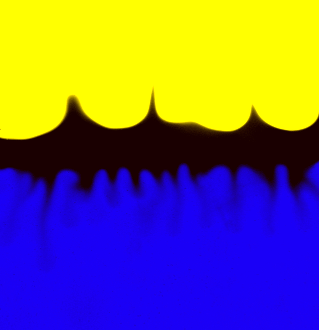
Contrary to the thermohaline instability, a dynamic mixing process like RTFI mixing is unknown in experimental chemo-hydrodynamics. It is unexpected as matter is mixed from a less dense layer into a denser one. However, similarly looking buoyancy-driven instabilities were indeed found in the laboratory at the interface between a solution of lighter hydrochloric acid (HCl) residing above a heavier solution of sodium hydroxide (NaOH) oriented vertically in the gravitional field by Zalts et al. (2008). The reaction of these two solutions at their common interface leads to the production of salt (NaCl), and to over-dense (with respect to the horizontal average) fingers of NaCl extending into the NaOH solution as shown in a snapshot from the experiment of De Wit (2008) or Almarcha et al. (2010) in Fig. 1. Such systems resemble principle similarities with the stellar shell convection models where lighter gas of higher mean molecular weight is residing above denser gas of lower mean molecular weight. Proposed explanations for this kind of laboratory mixing range from amplified local density fluctuations due to salt production, a local density decrease due to a temperature rise up to differences in the mass diffusion coefficients of the reacting species (Zalts et al. 2008). Recent work seems to favor the latter one (Almarcha et al. 2010). However, mass diffusion in stars is too slow to be responsible for the mixing observed in our simulations (see e.g., Michaud et al. (2008)).
| Model | Pop. | |||||
|---|---|---|---|---|---|---|
| M | I | |||||
| L | I | |||||
| O | I |


The paper is organized as follows. In Sect. 2 we discuss the input models for our simulations. Our hydrodynamic code and the hydrodynamic shell convection models together with the local and temporal properties of the RTFI mixing are described in Sect. 3. A possible theoretical explanation of RTFI mixing is discussed in Sect. 4, while the breaking of dynamic stability in stars is analyzed in Sect, 5. Finally, a summary of our findings is given in Sect. 6.
2 Initial Data
We used three initial models for our simulations (Tab. 1, Fig. 2), which correspond to the helium core of a 1.25 M⊙ star during the peak (maximum core luminosity) of the core helium flash computed with the GARSTEC code (Weiss & Schlattl 2000, 2007), the carbon-oxygen (C-O) core of a 9.3 M⊙ star at peak of the core carbon flash computed with the STAREVOL code (Siess 2006), and the core of a 23 M⊙ star during oxygen shell burning (Meakin & Arnett 2007) computed with the TYCHO code (Young & Arnett 2005). The thermodynamic structure of all three initial models is qualitatively similar exhibiting of an off-center temperature maximum due to nuclear burning in a partially electron degenerate stellar core. Directly outside this temperature maximum the inner boundary of a convective shell is located which extends towards larger radii.
The core helium flash occurs in low-mass stars () due to an off-center ignition of helium by the triple- reaction after central hydrogen exhaustion in the semi-degenerate helium core. The core carbon flash ensues after central helium exhaustion and is characterized by off-center carbon ignition in a semi-degenerate carbon core of a rather massive star (), the dominant nuclear reactions being 12C (12C, )Ne and 12 C(12C, p)Na followed by 16O (, )Ne. Oxygen shell burning is typical for massive stars () close to core collapse, when oxygen and carbon burn in a convective shell above a silicon-sulfur rich semi-degenerate core possessing an off-center temperature maximum (Arnett 1994; Bazan & Arnett 1998; Asida & Arnett 2000; Meakin & Arnett 2006, 2007).
During the core helium flash the convective shell is enriched mainly by 12C which results in a negative mean molecular weight gradient below its base (Fig. 2 a) 111The gradient grows for roughly 10 000 years since the onset of the core helium flash.. The situation is similar during the core carbon flash, where the nuclear ash from carbon burning increases the mean molecular weight inside its convective shell relative to that of the unburned inner carbon core (Fig. 2 b). Oxygen shell burning, which follows oxygen core burning, causes a positive composition gradient, i.e., the mean molecular weight increases in the direction of gravity at the bottom of the convective shell (Fig. 2 c).
3 Hydrodynamic Simulations
| model | Nr | Nθ | Nϕ | r | t | ||
|---|---|---|---|---|---|---|---|
| [cm] | [∘] | [∘] | [103s] | ||||
| hefl.2d.1 | 180 | 90 | - | 5.55 | 1.33 | - | 30 |
| hefl.2d.2 | 270 | 180 | - | 3.70 | 1 | - | 30 |
| hefl.2d.3 | 360 | 240 | - | 2.77 | 0.75 | - | 120 |
| hefl.3d | 180 | 90 | 90 | 5.55 | 1.33 | 1.33 | 3 |
| cafl.2d | 360 | 180 | - | 1.95 | 0.5 | - | 10 |
| oxfl.2d | 400 | 320 | - | 1.75 | 0.28 | - | 1 |
The numerical simulations were performed with a modified version of the hydrodynamic code Herakles (Mocák et al. 2008). The code employs the PPM reconstruction scheme (Colella & Woodward 1984), a Riemann solver for real gases according to Colella & Glaz (1984), and the consistent multi-fluid advection scheme of Plewa & Müller (1999). Self-gravity, thermal transport and nuclear burning are included in the code. Nuclear reaction networks are generated using a tool of Thielemann (private communication). In Table 2 we summarize some characteristic parameters of our 2D and 3D simulations based on the initial models given in Tab. 1.
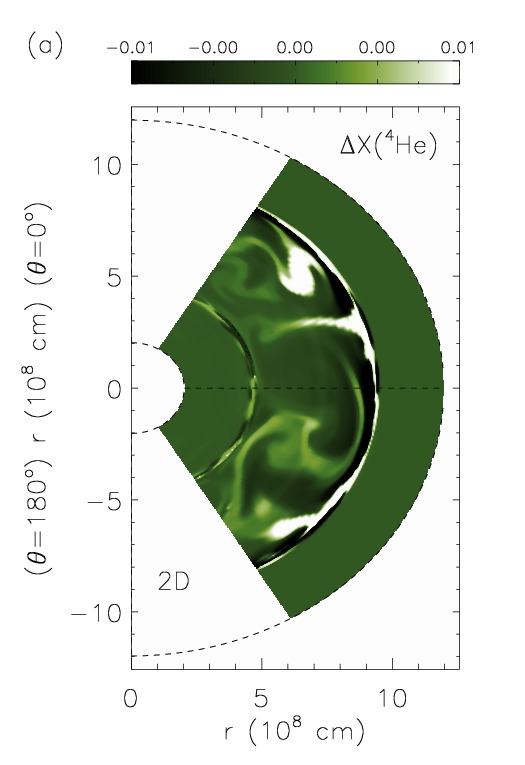
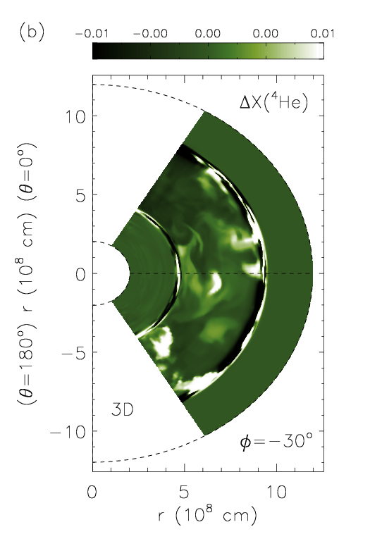
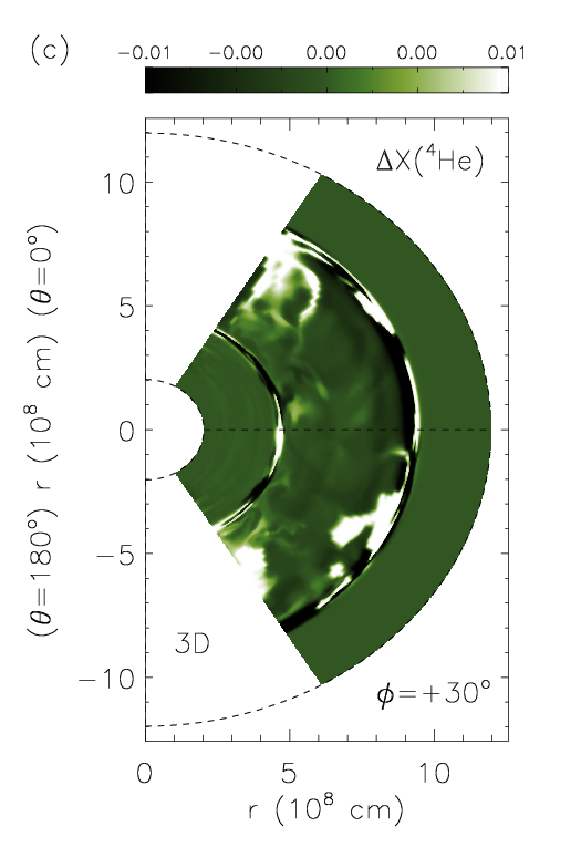
The core helium flash simulations were performed on an equidistant spherical polar grid in 2D () and 3D (). While the angular grid of the axisymmetric 2D simulations hefl.2d.2 and hefl.2d.3 covered the full angular range, i.e., , the 2D simulation hefl.2d.1 was restricted to the angular region . The 3D simulation hefl.3d was performed within an angular wedge given by and , respectively. This allowed us to simulate the 3D model with a reasonable amount of computational time using a radial and angular resolution comparable to that of the 2D model hefl.2d.1 for several convective turnover timescales (Fig. 3). In all core helium flash simulations the radial grid ranged from cm to cm. Boundary conditions were reflective in all directions except for simulations hefl.2d.1 and hefl.3d, where we utilized periodic boundary conditions in angular direction(s) to avoid a numerical bias in case of wide angular convective structures. Abundance changes due to nuclear burning were described by a reaction network consisting of the four -nuclei 4He, 12C, 16O, and 20Ne coupled by seven reactions.
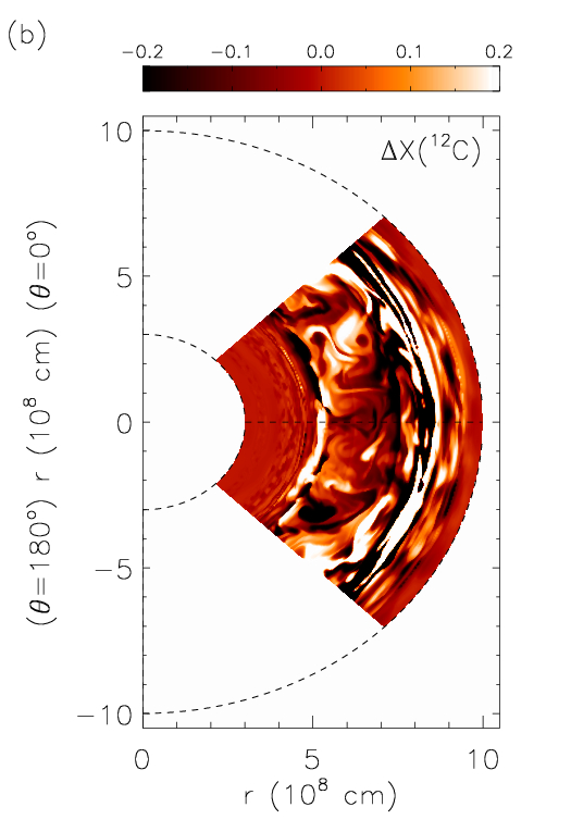
The core carbon flash simulation cafl.2d was performed on a 2D equidistant spherical polar grid () covering a 90∘ angular wedge centered at the equator (), and a radial grid ranging from cm to cm (Fig. 4). Boundary conditions were reflective in radial direction and periodic in angular direction. Abundance changes due to nuclear burning were described by a reaction network consisting of 1H, 4He, 12C, 14N, 16O, 20Ne, 22Ne, 23Na, and 24Mg coupled by 17 reactions.
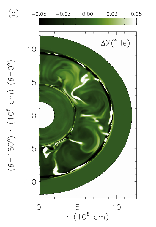
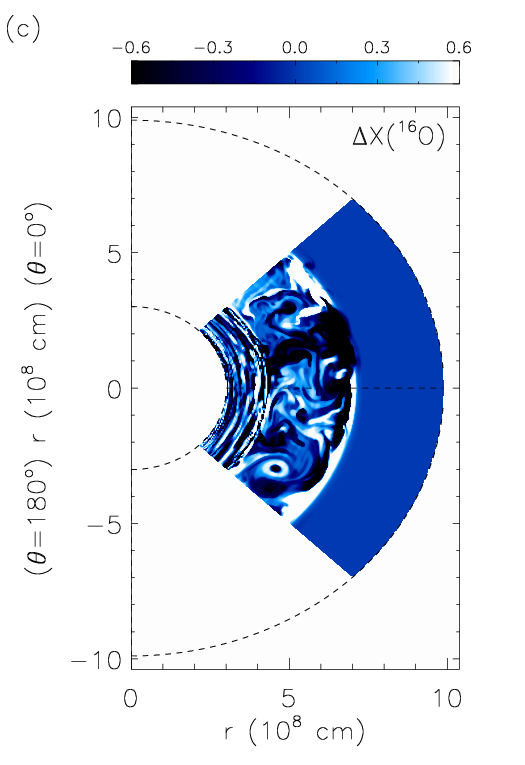
Oxygen shell burning simulation oxfl.2d was performed on a 2D equidistant spherical polar grid covering a 90∘ wedge centered at the equator, and a radial grid ranging from cm to cm (Fig. 4). Boundary conditions were reflective in radial direction and periodic in angular direction. Abundance changes due to nuclear burning were described by a reaction network consisting of neutrons, 1H, 4He, 12C, 16O, 20Ne, 23Na, 24Mg, 28Si, 31P, 32S, 34S, 35Cl, 36Ar, 38Ar, 39K, 40Ca, 42Ca, 44Ti, 46Ti, 48Cr, 50Cr, 52Fe, 54Fe, and 56Ni coupled by 76 reactions.
In the following subsections, we will briefly discuss one by one the main properties of our hydrodynamic shell convection models of the core helium flash, the core carbon flash, and the oxygen shell burning. This provides the basis for an assessment of RTFI mixing and its importance in a wider context.
3.1 Shell convection
3.1.1 Core helium flash
The hydrodynamic properties of shell convection during the core helium flash are described in detail in Mocák et al. (2008, 2009). Convection starts early (s) and quickly extends over the whole convectively unstable region as predicted by mixing length theory (MLT). In axisymmetry, the convection is characterized by fast and large circular vortices, while in 3D the convective flow is less ordered showing slower and smaller turbulent features. The relative fluctuations of density , temperature , and carbon 12C with helium 4He in the convection zone are of the order of 10-4, 10-4, 10-2 and 10-5, respectively (Fig. 3). The convective velocities in our 3D model match those predicted by MLT quite well (), whereas the velocities in our 2D models exceed those by up to a factor of four. Turbulent entrainment (Meakin & Arnett 2007) leads to a growth of the width of the convection zone on a dynamic timescale in both the 2D and 3D models due to an exchange between the potential energy contained in the stratified layers at the boundaries of the convection zone and the kinetic energy of the turbulent flow inside the convection zone.


3.1.2 Core carbon flash
An analysis of the hydrodynamic properties of shell convection during the core carbon flash, based on our 2D model cafl.2d, shows that the convective flow is dominated by small circular vortices. The maximum angular averaged velocities inside the convection zone exceed those predicted by MLT by about an order of magnitude. This is an unusual result, as in general, velocities inferred from 2D hydrodynamic simulations of shell convection typically exceed MLT velocities by a factor of five at most. The relative angular fluctuations of density and temperature are of the order of in the convection zone, while those of the carbon mass fraction C) are of the order of (Fig. 4). Whether turbulent entrainment is operative could not be decided, as the simulated timescales are too short. However, we intend to address this issue elsewhere.
3.1.3 Oxygen shell burning
The hydrodynamic properties of shell convection during oxygen shell burning are discussed in detail in Meakin & Arnett (2007). The findings of these authors are confirmed by our 2D model oxfl.2d very well. The angular averaged amplitudes of the convective velocities inferred from model oxfl.2d are . Turbulent entrainment has been detected in model oxfld.2d, too, but we have not further analyzed this phenomenon; for more details see Meakin & Arnett (2007). The relative angular fluctuations of density and temperature are of the order of in the convection zone, while for example those of the oxygen mass fraction O) are of the order of (Fig. 4). The similarity of these values with those in our models of the core helium and core carbon flash implies that the fluctuations of thermodynamic quantities seem not to depend on the specific type of shell convection.
3.2 Mixing below the convection zone in case of


We discovered a new mixing process operating below shell convection zones during degenerate, off-center helium and carbon burning (the core helium and carbon flash, respectively).
The process is characterized by a steep negative mean molecular weight gradient with , where lighter gas with a higher mean molecular weight resides above a denser gas of lower mean molecular weight. The (negative) gradient results from nuclear burning in the convection zone, and the assumption of instantaneous mixing used to calculate the corresponding stellar models.
In the following, we present the thermodynamic characteristics of such a mixing process during the core helium flash inferred from our 2D model hefl.2d.3, which was simulated with the highest grid resolution. Mixing is caused by overdense blobs enriched by material from the convection zone (e.g., carbon 12C) with higher mean molecular weight literally shooting down from the base of the convection zone towards the center of the star (i.e., in the direction of gravity). The blobs penetrate into denser layers of the core thereby creating finger-like structures (Fig. 5 a, b) which we also find in our 3D core helium flash model hefl.3d (Fig. 5 c, d). The properties of the mixing found in our hydrodynamic core carbon flash model are similar. Therefore, we discuss them only briefly at the end of this section.
A detailed analysis of the flow in the layers just beneath the base of the convection zone in model hefl.2d.3 revealed sinking dense blobs enriched by material with higher mean molecular weight than that of the ambient matter into which they penetrate. Resulting finger-like structures become visible immediately after convection starts in the layers below the temperature maximum. The finger-like structures can easily be spotted in maps showing relative angular fluctuations of the mean molecular weight, density, and temperature, respectively (Fig. 6 a - c). 222Note that in Figs. 5 and 6, which show the elongated finger-like structures, the maps are displayed in spherical coordinates ( and in cm and degree) using a rectangular projection. They grow continuously (Figs. 7 a), and reach a length of almost cm within the first s of evolution. Their width remains almost constant at a value of roughly 1-2cm during the entire simulation.
Although, the finger-like structures created by heavy sinking blobs of gas at earlier times eventually diminish 333The typical lifetime of a sinking heavy blob is about 350 s when our simulations have progressed for about 60 000 s., they are being constantly replaced by new heavy blobs again leaving behind trails of gas enriched by matter of larger . Thus, the layers into which the fingers penetrate are enriched by material of higher . Consequently, the initial value of rises by below the convective shell until the end of the simulation (Figs. 7a and 8) at a steadily increasing rate 444At the peak of the flash rises at a rate of s-1 within the convection zone, which is only twice faster than the rate of enrichment due to RTFI mixing below the convective shell..
The sink velocities of the overdense blobs are initially roughly reaching approximately at the end of the simulation at hrs. The blobs are always cooler and denser than the ambient matter by roughly and , respectively. Thus, the observed finger-like structures cannot be caused by the double diffusive instability which leads to ”salt-fingers”, as these are hotter than the surrounding matter leading to heat diffusion that is fast compared to diffusion of composition (Schmitt 1994).
Using the size of relative density fluctuations within the region where RTFI mixing takes place we can derive an analytic estimate for the velocity of the dense blobs causing the finger-like structures, if we assume that the blobs arise from a Rayleigh Taylor instability (Weiss et al. 2004). With , inferred from our simulation (Fig. 6 a), we find
| (1) |
where is the gravitational acceleration at the base of the convection zone, and the approximate length of the fingers (Fig. 7).
The above estimate agrees well with the results of an analysis of our simulation, where the gas inside the fingers sinks at a bit smaller velocities ranging from cm s-1up to cm s-1(Fig. 6 and 7). It confirms that the “buoyancy work” () is consistent with the acceleration of gas seen in the simulation, and suggests that the mixing is the result of the Rayleigh-Taylor instability. Hence, we propose to call it Rayleigh-Taylor finger instability mixing (RTFI). The velocities observed inside the finger-like structures (Fig. 6 e) are smaller than those predicted by Eq. (1), likely because of the friction caused by our numerical scheme between the ambient medium and the sinking overdense blob.


Note that the initial density fluctuations can result from wrinkling of the contact discontinuity at the boundary of the convection zone due to the convective flow, turbulence, g-modes or p-modes.
Eggleton et al. (2006) also found Rayleigh-Taylor instabilities driven by a molecular weight inversion caused by the 3He He,2p) 4He reaction in hydrodynamic simulations of the hydrogen-rich layers residing above the hydrogen burning shell in low-mass red giants. The corresponding mixing is qualitatively similar to RTFI mixing. The mixing velocities observed by Eggleton et al. (2006) agree very well with those theoretically estimated for a RT instability according to the formula , where equal relative density and composition fluctuations, i.e., , were assumed. However, any density fluctuation will necessarily lead to composition and temperature fluctuations as well. Moreover, the formula of Eggleton et al. (2006) holds only for an ideal gas, and only if the blobs are in pressure equilibrium with the ambient medium and have the same temperature as the surrounding matter.
The finger-like structures resulting from RTFI mixing in our simulations are in pressure equilibrium with the surrounding gas, as they move with subsonic velocities (the speed of sound is in the corresponding layers). However, they are always cooler than the ambient medium, i.e., , where is the temperature of the ambient medium. Allowing also for fluctuations of the mean molecular weight , pressure equilibrium ( implies for an ideal gas equation of state
| (2) |
Solving for this relation should provide an improved estimate for the relative density variation in Eq. (1):
| (3) |
However, in our models RTFI mixing operates in a partially electron-degenerate core, i.e., the assumption of an ideal gas equation of state is not justified as it was the case in Eggleton et al. (2006). Using the formula of Eggleton et al. (2006) the velocity of the sinking overdense blobs of RTFI mixing can be estimated to be v (), while Eqs. 1 and 3 lead to the considerably larger value (, ), because the density contrast inferred from Eq. 3 is roughly an order of magnitude larger than that observed in the simulations.
We point out here once more that although the finger-like structures resemble overshooting, they actually originate from density fluctuations just beneath the lower boundary of the convection zone (Fig. 9 a) where the gas is already cold compared to that in the convection zone (Fig. 9 b), but still partially enriched by matter from the adjacent convection zone. The fingers are also neither directly connected with sinking plumes inside the convection zone nor with large density fluctuations seen at the lower convection zone boundary (Fig. 9 c).


There exists a correlation 555The correlation is not very clear during the first s, as it is difficult to determine the number of fingers during this early epoch. To identify a finger one searches for overdense regions below the base of the convective shell that correspond to sinking blobs. Focusing on fluctuations in is misleading, as these often exist only as traces behind sinking heavy blobs. between the maximum value of the square of the Brunt-Väisälä frequency and the number of new fingers (heavy blobs) appearing at a given time (Fig. 7 b). varies between and for the 2D model hefl.2d.3. This can be understood, as the fingers are caused by overdense blobs of gas and the Brunt-Väisälä frequency can be related to the amplitude of the density oscillations according to
| (4) |
Another well known interpretation of relates it to the frequency of g-modes or internal gravity waves:
| (5) |
where is the logarithmic temperature gradient in the ambient surrounding, gives the temperature change for an adiabatic displacement, and the corresponding logarithmic composition gradient. Furthermore, we have and , where the partial derivatives are evaluated at constant values of and , respectively. Finally, is the pressure scale height.
The correlation tells us that larger density fluctuations (larger values of ) result in the formation of denser and therefore heavier blobs of gas at the bottom edge of the convection zone, which sink more easily down into the core. Such blobs do not have to be extremely heavy (dense) initially. It is sufficient when their density remains higher than that of the ambient medium on length scales comparable with the size of the observed finger-like structures. The dense blobs sink down from the bottom edge of the convection zone to layers, which are about denser than those from where the blobs are created (Fig. 9). This is possible as the sinking blobs are compressed, because they remain in pressure equilibrium with the ambient medium. Thus, the situation is exactly opposite to that encountered in the case of convection, where hot blobs of relatively dense gas rise from the bottom of the convection zone over large distances because they expand, although their initial density is much higher than that of the layers where they eventually end up.
No or only a weak correlation can be recognized between the flow in the convection zone and the occurrence of sinking dense blobs (causing the finger-like structures) when comparing the temporal evolution of the total kinetic energy of the convective flow and the number of fingers appearing at a given time (up to six) or the maximum of the Brunt-Väisälä frequency squared (Fig. 7 c). However, there exists a correlation between the positions of the hot spots at the base of the convection zone and the locations where the fingers appear. Fingers occur more frequently at the positions of the temperature maxima (by ) as compared to any other place beneath the convection zone, the temperature maxima being typically connected with convective upflows.
We have no explanation for the observed periodic behavior of , and for the occurrence period of the finger-like structures (Fig. 7 b), which is roughly s (or convective turnover timescales) at s and decreases at later times. The periodicity seems to be uncorrelated with the convection as the total kinetic energy of the convective flow and are not clearly correlated (Fig. 7 c).
We have also found RTFI mixing in multidimensional models of shell convection during the core carbon flash, which suggested to us that a crucial ingredient for the operation of the instability is the presence of a composition gradient, not necessarily coinciding with the bottom of convection zone. During the core carbon flash mixing leads to the formation of several layers enriched by matter of a larger mean molecular weight separated by interfaces with high values of (Fig. 10, a) indicating large density fluctuations (Eq. 4). The bottom two layers are completely detached from the convection zone whose lower edge is located at cm. The radial distribution of across these layers shows a staircase-like behavior, which is similar to that observed in experiments of thermohaline mixing, i.e., a thermohaline staircase (Krishnamurti 2003).
3.3 Mixing below the convection zone in case of
In order to test our preliminary conclusion based on 2D shell convection models of the core helium flash and the core carbon flash, which both have a negative composition gradients at the base of the convection zone, we have simulated in addition a 2D hydrodynamic model of shell convection during the oxygen shell burning in a massive star. The corresponding stellar model is characterized by a layer having a positive mean molecular weight gradient at the base of the convection zone. For this situation we do not find the finger-like structures of RTFI mixing beneath the base of the convection zone (cm) (Fig. 10 b).
4 Stability Versus Local Perturbations
For assessing the dynamic stability of a stellar layer we consider a fluid element which is radially displaced by an amount from its initial position (Kippenhahn & Weigert 1990). The density of the fluid element will differ at its new position from that of its surrounding by
| (6) |
where is the density change of the fluid element when it rises a distance , and is the density gradient of the surrounding matter.
According to e.g., Kippenhahn & Weigert (1990) a stellar layer is unstable against convection, if a fluid element that is initially lighter than its surrounding will continue to rise when it is displaced against the direction of gravity (i.e., ). Hence convection sets in when the following criterion is fulfilled:
| (7) |
where the differentials refer to changes in radial direction. If it is assumed that the fluid element moves sufficiently fast, it moves adiabatically, and hence . Note that the same criterion also holds for a fluid element that is initially heavier than its surrounding, and hence sinks downward (i.e., ) in the direction of gravity. Note further that such an over-dense fluid element will sink downward as long as its density remains higher than that of the surrounding matter.
Allowing also for (radial) composition gradients within the stellar layers Eq. 7 leads to the well known Ledoux instability criterion (see e.g., , Kippenhahn & Weigert (1990))
| (8) |
where , , , and are defined above (see paragraph after Eq. 5).
The Ledoux criterion determines dynamically unstable regions in a star. Hence, if we could identify layers in our hydrodynamic models beneath the base of the convection zone where the inequality Eq. 8 holds, we could prove that the over-dense blobs which start sinking downward from there and causing RTFI mixing, are the result of a Ledoux unstable stratification. Indeed we find that the left term of Eq. 8 i.e., is positive in our 2D core helium flash model in most grid zones where we observe RTFI mixing (see white regions in Fig. 6 f).


As mentioned before RTFI mixing is similar to mixing by convection in stars characterized by hot blobs except that it is caused by sinking cold dense blobs enriched with gas of larger mean molecular weight. However, there exists another important difference between both dynamic mixing processes. In convection the surrounding gas has to have a superadiabatic temperature gradient in order for convection to set in, while RTFI mixing sets in even if the correspoding layers are initially dynamically stable and Ledoux instability criterion is not fullfilled. In the latter case becomes the stability broken only subsequently in our simulations, when convection boundary becomes partially enriched by material with higher from convection zone and its enriched dense blobs start to sink.
As it seems that, the -gradient is the reason for the observed instability, we analyzed in more detail the dependence of on near the boundary of the convection zone. Using the equation of state ), we rewrite the relative (radial) variation of the density as
| (9) |
where the partial derivative is taken at constant and . Layers are stable as long as their density gradient does not exceed the density change experienced by a displaced fluid element (Eq. 7), which we assumed to be equal to the adiabatic gradient .
The radial distributions of and are shown in Fig. 11(a) for our 2D oxygen shell burning model oxfl.2d near the base of the convection zone . We analyzed the stability of these layers by calculating the total differential (Eq. 9), which depends on the pressure, temperature, and composition gradients (, and , respectively). Given the positive -gradient of the model, we find that is always smaller than at the boundary of the convection zone implying dynamic stability. Assuming for the composition gradient the same absolute value, but the opposite sign, we find that exceeds below the lower edge of the convection zone, i.e., the corresponding stellar layers at cm become unstable.
The positive -gradient therefore reduces , making the layer more stable. The effect of a negative -gradient is exactly opposite leading to an increase of and a less stable situation compared to that with a positive -gradient.
The destabilizing effect at the base of our core helium flash model is rather small ( ) due to the smallness of the -gradient, but apparently strong enough to instigate RTFI mixing. This can be infered from Fig. 11(b), where exceeds its adiabatic counterpart below the convection zone for cm.
Hence, the driving element behind RTFI mixing is a negative -gradient.
5 Discussion
Despite the observed existence of dynamic mixing in stars driven by chemical gradients, its inclusion into stellar evolutionary calculations imply non existing observational evidence. Motivated by mixing driven by the 3He inversion found in hydrodynamic simulations of hydrogen layers in low-mass red giants by Eggleton et al. (2006), Denissenkov & Pinsonneault (2008) discovered that the time which stars spend in the bump while climbing the red-giant branch is significantly prolonged.
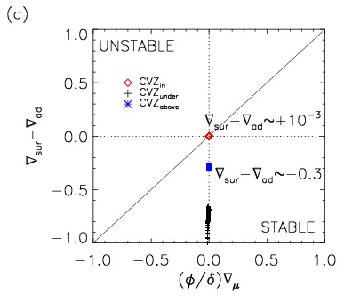
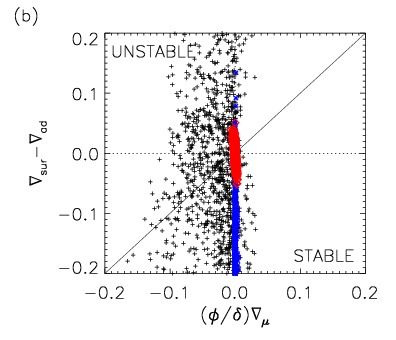
These finding suggests that layers with a negative gradient of the mean molecular weight should not become unstable on dynamical timescales. However, we observe just the opposite in our hydrodynamic simulations, where is a very common situation, as demonstrated by Fig. 12. It depicts the stability properties of individual grid zones in the temperature () composition gradient plane.
Initially, all grid zones above and below the convection zone have a sub-adiabatic temperature gradient () and thus are stable, while for grid zones in the convective shell the temperature gradient exceeds the adiabatic one by 10-3 rendering them unstable (Fig. 12 a). After the onset of convection the situation changes considerably (Fig. 12 b). Whereas the temperature gradient remains super-adiabatic in many grid zones inside the convection zone, some of these zones become sub-adiabatic and their composition changes. This can be understood by realizing that convection consists of rising hot plumes (super-adiabatic) of gas enriched by nuclear ash from nuclear burning and sinking cold plumes (sub-adiabatic) mixed with gas from layers further out. Chemical species are mixed quite uniformly throughout the evolved convection zone,i.e., the corresponding grid zones tend to gather at . On the other hand, some zones from below the base of the convection zone become dynamically unstable as their is positive. These are the zones which participate in RTFI mixing.
6 Summary
We have performed multidimensional hydrodynamic simulations of shell convection based on three different initial models. These correspond to helium core at the peak of the core helium flash in a low-mass star, carbon core during the core carbon flash and oxygen burning shell above silicon-sulfur rich core of a massive star.
We find a mixing process under the base of convection zones manifesting itself as over-dense blobs sinking in the direction of gravity and originating in the convection boundary, which lead to appearance of overdense fingers enriched by gas of higher mean molecular weight. This mixing is likely a result of the Rayleigh-Taylor instability operating due to the presence of negative mean molecular weight gradient () . This is mainly confirmed by approximate match between theoretical velocity estimate for an element of matter with excess density over the average of its surrounding and observed velocities in our 2D simulation with highest resolution. The theoretical velocities based on observed amplitude of density fluctuations in the fingers give us a value of cm s-1, which is close to the observed velocities reaching values v cm s-1. The fingers are denser and colder than their surrounding, which rules out their possible explanation as the thermohaline mixing. The observed fingers lead to a mixing of material with higher mean molecular weight from convection boundary partially enriched by gas from above-lying convection zone deeper to stellar cores and we call it Rayleigh-Taylor finger instability mixing or the RTFI mixing. The sinking over-dense blobs which cause the fingers are literally shooting from the convection boundary downwards. The number of such fingers appearing at given time is correlated with maximum of square of Brunt-Väisälä frequency in the convective boundary, as it is proportional to the amplitude of density fluctuations. If the regarded amplitude of N2 is higher in the convection boundary, the fluctuations there are stronger (heavier) too. This in turn increases the likelihood of having heavy blobs of gas which can sink and create the fingers. The frequency at which the fingers appear is not clearly correlated with above-lying convection. However, preferred spots from where the fingers start are correlated with temperature maxima just above the convection boundary, which one can associate with up-flows in the convection zone.
We find similar mixing below the base of the convection zone in the carbon core during the core carbon flash, too. However, we did not observe it below the base of the convection zone in our model of shell convection in oxygen burning shell. The only qualitative difference of the oxygen burning shell model compared to the others is a positive mean molecular weight gradient (i.e., increasing in direction of gravity) at the bottom of its convection zone. Hence, we conclude that the condition must be the driving element of RTFI mixing. We could confirm this also analytically for the oxygen shell burning model by examining the dependence of density fluctuations on the -gradient at the lower convection zone boundary.
Implications of RTFI mixing for stellar evolution have still to be explored. While it almost certainly will not influence the core helium flash considerably, it could, for instance, have some important influence on the properties of the deflagration flame during the core carbon flash.
Acknowledgements.
The simulations were performed at the computer center of the Max-Planck-Society in Garching (RZG). Miroslav Mocák acknowledges financial support from the Communauté francaise de Belgique - Actions de Recherche Concertées, and from the Institut d’Astronomie et d’Astrophysique at the Université Libre de Bruxelles (ULB). The authors thank Lionel Siess and Casey Meakin for providing us with initial stellar models. We also want to thank Christophe Almarcha and Anne De Wit for enlightning discussions on chemo-hydrodynamics, and for supplying Figure 1 to us. Finally, we express our gratitude to Lionel Siess, Rob Izzard, and Casey Meakin for valuable discussions, and for helpful comments on the manuscript.References
- Almarcha et al. (2010) Almarcha, C., Trevelyan, P. M. J., Riolfo, L. A., et al. 2010, The Journal of Physical Chemistry Letters, 1, 752
- Arnett (1994) Arnett, D. 1994, ApJ, 427, 932
- Asida & Arnett (2000) Asida, S. M. & Arnett, D. 2000, ApJ, 545, 435
- Bazan & Arnett (1998) Bazan, G. & Arnett, D. 1998, ApJ, 496, 316
- Colella & Glaz (1984) Colella, P. & Glaz, H. H. 1984, J.Comp.Phys., 59, 264
- Colella & Woodward (1984) Colella, P. & Woodward, P. R. 1984, J.Comp.Phys., 54, 174
- De Wit (2004) De Wit, A. 2004, These d’Agregation de l’Enseignement Superieur (Habilitation)
- De Wit (2008) De Wit, A. 2008, Chimie Nouvelle, 99, 1
- Dearborn et al. (2006) Dearborn, D. S. P., Lattanzio, J. C., & Eggleton, P. P. 2006, ApJ, 639, 405
- Denissenkov & Pinsonneault (2008) Denissenkov, P. A. & Pinsonneault, M. 2008, ApJ, 684, 626
- Deupree (1996) Deupree, R. G. 1996, ApJ, 471, 377
- Eggleton et al. (2006) Eggleton, P. P., Dearborn, D. S. P., & Lattanzio, J. C. 2006, Science, 314, 1580
- Fernando (1991) Fernando, H. 1991, Ann.Rev.Fluid Mech., 23, 455
- Gargett & Schmitt (1982) Gargett, A. E. & Schmitt, R. W. 1982, J. Geophys. Res., 87, 8017
- Grossman & Taam (1996) Grossman, S. A. & Taam, R. E. 1996, MNRAS, 283, 1165
- Herwig et al. (2006) Herwig, F., Freytag, B., Hueckstaedt, R. M., & Timmes, F. X. 2006, ApJ, 642, 1057
- Kippenhahn et al. (1980) Kippenhahn, R., Ruschenplatt, G., & Thomas, H. 1980, A&A, 91, 175
- Kippenhahn & Weigert (1990) Kippenhahn, R. & Weigert, A. 1990, Stellar Structure and Evolution (Stellar Structure and Evolution, XVI, 468 pp. 192 figs.. Springer-Verlag Berlin Heidelberg New York. Also Astronomy and Astrophysics Library)
- Krishnamurti (2003) Krishnamurti, R. 2003, J.Fluid Mech., 483, 287
- Meakin & Arnett (2006) Meakin, C. A. & Arnett, D. 2006, ApJ, 637, L53
- Meakin & Arnett (2007) Meakin, C. A. & Arnett, D. 2007, ApJ, 667, 448
- Michaud et al. (2008) Michaud, G., Richer, J., & Richard, O. 2008, ApJ, 675, 1223
- Mocák et al. (2008) Mocák, M., Müller, E., Weiss, A., & Kifonidis, K. 2008, A&A, 490, 265
- Mocák et al. (2009) Mocák, M., Müller, E., Weiss, A., & Kifonidis, K. 2009, A&A, 501, 659
- Plewa & Müller (1999) Plewa, T. & Müller, E. 1999, A&A, 342, 179
- Rayleigh (1883) Rayleigh, L. 1883, Proceedings of the London mathematical society
- Schmitt (1994) Schmitt, R. W. 1994, Annual Review of Fluid Mechanics, 26, 255
- Siess (2006) Siess, L. 2006, A&A, 448, 717
- Stancliffe et al. (2009) Stancliffe, R. J., Chieffi, A., Lattanzio, J. C., & Church, R. P. 2009, Publications of the Astronomical Society of Australia, 26, 203
- Stancliffe & Glebbeek (2008) Stancliffe, R. J. & Glebbeek, E. 2008, MNRAS, 389, 1828
- Sweigart & Gross (1978) Sweigart, A. V. & Gross, P. G. 1978, ApJS, 36, 405
- Taylor (1949) Taylor, G. 1949, Proceedings of the Royal Society of London. Series A, Mathematical and Physical Sciences
- Thomas (1967) Thomas, H.-C. 1967, Zeitschrift fur Astrophysik, 67, 420
- Turner (1985) Turner, J. 1985, Ann.Rev.Fluid Mech., 17, 11
- Weiss et al. (2004) Weiss, A., Hillebrandt, W., Thomas, H.-C., & Ritter. 2004, Cox and Giuli’s Principles of Stellar Structure (Gardners Books)
- Weiss & Schlattl (2000) Weiss, A. & Schlattl, H. 2000, A&AS, 144, 487
- Weiss & Schlattl (2007) Weiss, A. & Schlattl, H. 2007, Ap&SS, 341
- Williams (1974) Williams, A. J. 1974, Science, 185, 941
- Young & Arnett (2005) Young, P. A. & Arnett, D. 2005, ApJ, 618, 908
- Zalts et al. (2008) Zalts, A., C.El., H., Rubio, D., Ureña, A., & D’Onofrio, A. 2008, Physical review E