Pulse trapping inside one-dimensional photonic crystal with relaxing cubic nonlinearity
Abstract
We theoretically study the effect of pulse trapping inside one-dimensional photonic crystal with relaxing cubic nonlinearity. We analyze dependence of light localization on pulse intensity and explain its physical mechanism as connected with formation of dynamical nonlinear cavity inside the structure. We search for the range of optimal values of parameters (relaxation time and pulse duration) and show that pulse trapping can be observed only for positive nonlinearity coefficients. We suppose that this effect can be useful for realization of optical memory and limiting.
pacs:
42.65.Tg 42.65.Re 42.65.Hw 42.70.QsI Introduction
Photonic-band-gap structures are actively studied as promising elements for different devices of nonlinear and quantum optics Yabl ; Bert ; Joan . Study of nonlinear photonic crystals is connected with the possibility of dynamical adjustment of the parameters of the system. Photonic crystals (including two- and three-dimensional) allow to control dispersion and diffraction properties of light Stal ; Chutinan , obtain pulse reshaping Vujic , pulsed high-harmonic generation Scalora , etc. The processes of light self-action in such systems result in localization effects such as gap solitons formation, discrete mode existence or light energy localization (see, for example, Ming00 ; Ming01 ; Ming02 ; Sukh ).
The simplest example of one-dimensional photonic crystal can be represented as a periodic set of alternating dielectric layers with large depth of refractive index modulation. One of the most prominent effects of nonlinear optics of such structures is strong pulse compression in photonic crystals with non-resonant cubic nonlinearity Eggl ; Zhelt . The effect of light pulse localization, or trapping, in one-dimensional photonic crystal with a defect was studied in Ref. Good and, in more general form, in Refs. Mak1 ; Mak2 .
In this paper we study pulse propagation in photonic crystal with relaxing cubic nonlinearity. It is obvious that if we reduce incident pulse duration, the inertial properties of medium nonlinearity should be taken into account. Indeed, the lowest values of relaxation time connected with the electronic Kerr mechanism (a few femtoseconds Akhm ) appear to be comparable with pulse durations obtained at the modern set-ups. As it was shown in Ref. Vlasov , relaxation of nonlinearity results in vanishing of the effect of femtosecond pulse compression which can be obtained in relaxation-free case.
In our research we use numerical simulations of the Maxwell wave equation taking into account the process of nonlinearity relaxation. The method used allows to obtain numerical solutions of the problem without any assumptions about medium parameters modulation or rate of variation of field envelope. We show that, in a certain region of pulse amplitudes, relaxation times and pulse durations, the pulse can be trapped inside a nonlinear cavity dynamically formed by the light. Appearance of the cavity is connected with local change of reflective properties of the photonic structure. In other words, dynamical shift of band spectrum occurs. Trapping pulse inside the photonic crystal is a prospective effect for such possible applications as optical limiters (which transmit light only with proper intensity), optical buffers or memory (which allows to store light for time, large in comparison with characteristic transmission time). Large advantage of the scheme considered is absence of necessity to introduce nonuniformity or any imperfections in the structure of nonlinear photonic crystal.
The article is divided into several sections. In Section II the main equations are given and the approach for numerical solving the wave equation is considered. Section III is devoted to some phenomenological aspects of pulse trapping effect. In Section IV the physical mechanism of pulse trapping in photonic crystal with relaxing cubic nonlinearity is discussed. Finally, in Section V we consider some conditions for pulse trapping observation connected with the proper choice of pulse duration and relaxation time.
II Main equations and numerical method
In this paper we consider ultrashort pulse interaction with one-dimensional photonic crystal made of substance with relaxing cubic (Kerr) nonlinearity. Light propagation along -axis is governed by the Maxwell wave equation
| (1) |
where is electric field strength, is medium refractive index that depends on light intensity as
| (2) |
Here is a linear part of refractive index. Time dependence of nonlinear term is responsible for relaxation process and is described by the first-order differential equation due to the Debye model of nonlinearity Akhm
| (3) |
where is Kerr nonlinear coefficient, is the characteristic relaxation time. We consider fast relaxing media (electronic Kerr mechanism) with relaxation times as small as few femtoseconds. Representing field strength as , where is a carrier frequency, is the wavenumber, and introducing new, dimensionless arguments and , we come to the wave equation for the pulse amplitude ,
| (4) |
Usually, second-order derivatives are neglected at this point resulting in slowly varying envelope approximation. However, in the case of abrupt changes of refractive index (photonic crystal) it may fail, so that we should solve the full Eq. (4). In addition, this equation allows to describe the behavior of electric field in the structure without division into forward and backward waves. Equation (4) and the computational scheme considered below are similar to those of Refs. Cren96 ; Novit where they were implemented to consider light propagation in a dense resonant medium and a photonic crystal containing it.
Equation (4) can be solved numerically by using the finite-difference time-domain (FDTD) approach. The computational scheme is based on calculation of amplitude value at every mesh point as
| (5) |
Here the auxiliary values are
The values of refraction index at the mesh points can be obtained in terms of finite-difference representation of Eqs. (2)-(3),
| (6) |
where , and are the values of the background refraction index and nonlinearity coefficient at .
To correctly set the boundary conditions we use the total field / scattered field (TF/SF) method and the perfectly matched layer (PML) method which allows to apply the so-called absorbing boundary conditions at the edges of the calculation region Anantha .
III Pulse trapping effect
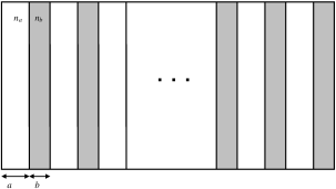


Let us consider propagation of ultrashort (femtosecond) light pulse in one-dimensional photonic crystal shown in Fig. 1. Spatial periodic modulation of the background refractive index defines the structure of it, so that it can be treated as a set of alternate layers. The parameters used in calculations are as follows: refractive indices of the layers , ; their thicknesses , m; number of layers . Nonlinear coefficient of the material is defined as , i.e. the pulse amplitude is normalized by the value . This value of cubic coefficient provides refraction index change of thousandth and hundredth of unity and was used in calculations of Ref. Vlasov . Note that nonlinear coefficient is positive (focusing nonlinearity), so that refractive index increases with the intensity. The incident pulse is assumed to have Gauss envelope . Here is a pulse duration which further takes on the value of fs, while the carrier frequency lies on the wavelength m.
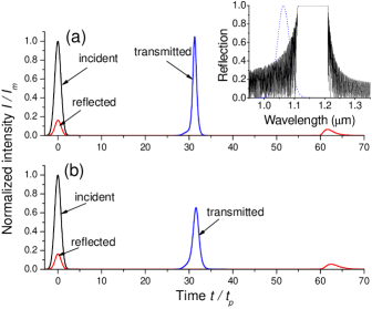
Figure 2 shows the results of calculations of pulse interaction with nonlinear photonic structure with and without relaxation. One can easily see that the effect of pulse compression (obtained at ) is completely absent when fs. This result is in strict accordance with the conclusions of Ref. Vlasov .
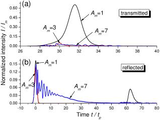
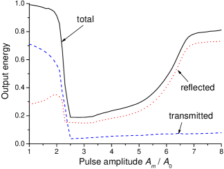
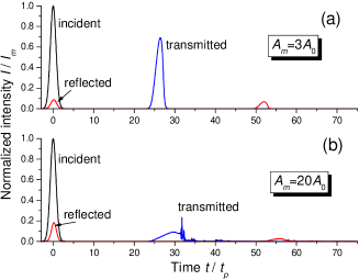
Vanishing of compression effect in Fig. 2 was obtained for pulse peak intensity , where is the value of intensity corresponding to . If we take greater , the transmitted pulse continues to decrease. As it is seen in Fig. 3(a), only small part of incident light can pass through the nonlinear photonic crystal at . This situation is observed at as well, though the reflected pulse gets larger in this last case [Fig. 3(b)]. When we integrate intensity of reflected and transmitted light over a certain time interval ( in our calculations, i.e. large enough in comparison with time required for pulse to pass through the photonic crystal which is about , see Fig. 2), we obtain the characteristic energy curves (Fig. 4) that describe the change in behavior of pulses as their peak intensity is increasing. It is seen that, when gets larger than , reflected, transmitted and overall (summarized) energies demonstrate dramatic decrease. After reaching the minimum (output energy is about percent of the input one), the curves begin to rise slowly. This slow growing of transmitted energy continues, while, for reflected and total ones, rise becomes more steep (especially, when ) and, finally, the plateau is observed for . Thus, the input energy almost entirely transforms to reflected light at high intensities of incident pulse.
It is obvious that the energy of pulses with amplitudes between and is confined inside the photonic crystal. Figure 5(a) demonstrates light intensity distributions along the length of the structure at different instants of time for the pulse peak amplitude . At first (), the most part of pulse energy is localized in a narrow region of the nonlinear photonic crystal, near the position m (the total length of the structure is about m). As time goes by, energy tends to redistribute more uniformly. Nevertheless, there is still pronounced maximum of intensity distribution, moreover it is shifted towards larger positions, namely m at . At large time points this distribution stays almost invariant, or stationary. Its maximum only slightly decreases, which seems to be connected rather with further redistribution than with output radiation. Anyway, even at approximately percent of pulse energy is still confined inside the photonic structure, just as at (see Fig. 4). This time is more than 100 times higher than the interval needed for pulse to pass through the system. Recalling that , this delay time in absolute units is greater than ps. Therefore we can say about pulse trapping in this case. Only for the system starts to slowly emit light so that the sharp distribution shown in Fig. 5(a) becomes violated. More detailed calculations show that even at about percent of the initial energy is still inside the photonic crystal, though it is distributed much more uniformly.
Now let us consider the pulse with . The corresponding spatial distributions are shown in Fig. 5(b). It turned out that in this case the pulse is localized near the very beginning of the structure. In this position it rapidly loses energy which is mainly radiated through the front (input) end of the system. So this radiation gives significant contribution to reflection [see Fig. 3(b)]. After light intensity becomes lower than a certain threshold, the pulse starts moving and widening. It moves quite slowly, so that some part (about percent) of the input energy is confined inside the photonic crystal for a long time, but the peak intensity of the distribution is very low if we compare with the case of .
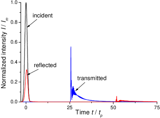
It is interesting to compare pulse behavior considered with pulse propagation in photonic crystal with relaxation-free nonlinearity, i.e. at . Intensity distributions inside the system for this case are demonstrated in Fig. 6. It is seen that there is no any long-term energy localization in non-relaxing photonic structure. Light exhibits only chaotic ”wander” inside it and simultaneous attenuation due to emitting through input and output ends. Finally, almost all energy of the pulse is already radiated by the instant of time . Therefore we can say that relaxation of nonlinearity is a necessary condition to obtain the effect of pulse trapping inside a photonic crystal.
IV Physical mechanism of pulse trapping
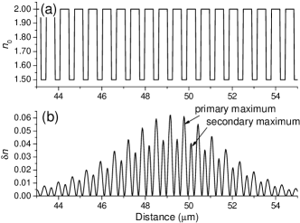

What is the physical reason, or mechanism, of this phenomenon? As pulse propagates inside the photonic crystal possessing cubic nonlinearity, refractive index of the structure changes dynamically according to light intensity. If nonlinearity is relaxation-free, these changes are instantaneous and depend entirely on field distribution at current instant of time. In the case of relaxing nonlinearity, nonlinear variation of refractive index ( in our notation) can form a certain stable structure due to retardation in its change. Appearance of this nonlinear dynamical ”cavity” results in pulse trapping: light tends to change the distribution of and leave the cavity, but inertia of nonlinearity stabilizes it so that intensity is transformed to provide steady spatial distribution . The example of this is shown in Fig. 7(b). One can see that maximal values of nonlinear variation of refractive index (so-called primary maxima) are achieved in the layers with low linear refractive index [see Fig. 7(a)]. This is in accordance with the effect of light concentration in low refractive index regions of photonic crystal for radiation tuned to high-frequency side of reflection spectrum Bert as it is in the case considered (see the inset in Fig. 2). On the other hand, high refractive index layers of the structure contain minor (secondary) maxima of .
Obviously, low-intensity initial pulses are insufficient to produce high enough nonlinear contribution , so that pulse is mainly transmitted and reflected during short time after pulse incidence. For higher intensities [e.g. as in Fig. 5(a)] pulse forms nonlinear cavity inside the photonic crystal which localizes the most part of pulse energy. Though this cavity slowly tends to uniformity of and loses its energy, it allows to trap pulse light for relatively large time interval. This behavior is obtained in wide range of pulse amplitudes, approximately from to . As pulse intensity increases, cavity formation position moves towards the front end of the photonic structure. Finally, for the nonlinear cavity appears so close to the entrance of the system [Fig. 5(b)] that it rapidly emits almost all its energy in the form of reflected light. That is why only intermediate intensities of pulse (not too low and not too high) are suitable to obtain the effect of trapping pulse inside the structure considered.
Finally, we should explain the role of photonic crystal in this process. Is it necessary to use photonic-band-gap structure or, maybe, the effect of pulse trapping can be observed in a uniform cubic medium? To clarify this question we performed calculations of pulse interaction with the medium possessing relaxing nonlinearity and mean refractive index . One can see [Fig. 8(a)] that in this case there is no any light localization for pulse amplitude . Only much more intensive pulses start to lose considerable part of energy inside the medium. For example, about percent of pulse energy is found to be trapped for [Fig. 8(b)]. This part of energy stays inside the uniform medium for a long time and is connected with corresponding nonlinear variation of refractive index (see Fig. 9 for the instant of time ). However, the distribution of light intensity in the uniform medium seems to be stochastic and does not resemble pulse envelope as in the case of nonlinear photonic crystal [compare the distributions in Figs. 9(a) and 5(a)]. Therefore we cannot call light localization in the uniform medium with relaxing nonlinearity by the pulse trapping in the full sense of this term. Moreover, in photonic crystals we need pulse intensities which are less by an order of magnitude than in the case of the uniform medium.
Perhaps, the nonlinear cavity formation is connected with local change of reflective properties of photonic crystal. This results in dynamical shift of the band spectrum of the structure. To examine this situation we consider the refractive properties (for the central wavelength m) of the structure with refractive index variations shown in Fig. 10(a) [it corresponds to intensity distribution of Fig. 5(a) at ]. We calculate reflectivity of the partial structures, which include the layers from the input to a certain final position (inside the whole photonic crystal), and compare it with the case of linear structure. Difference between reflectivities in this two cases as a function of final position is demonstrated in Fig. 10(b). It is seen that the structure with modified refractive index modulation provides locally large reflectivity deviations from the linear case. This deviations mainly appear at large positions inside the crystal where is high enough, so that they can prevent light propagation in forward direction. Similar situation is observed if we consider backward propagation. Hence, it turns out that light is trapped in the central region of the structure. Finally, it is worth noting that this picture of refractive index variations and reflectivity deviations is permanently changing, though it is stabilized by the relaxing properties of nonlinearity.

V On optimal conditions of pulse trapping
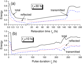

In previous sections we considered the effect of pulse trapping in photonic crystal with relaxing cubic nonlinearity only for a single set of time parameters: fs and fs. Fig. 11(a) shows the dependence of output energies (reflected, transmitted and total) on relaxation time at fixed value of pulse duration fs. The behavior of these dependencies is similar to that of the curves in Fig. 4: abrupt drop in the range of small (less than fs), smooth increasing and, finally, steep rise of the curves for reflected and total energies. The full range of relaxation times where the pulse trapping can be observed is rather wide: from a fraction of femtosecond (relaxation is so fast that it does not influence the pulse) to about fs that is much greater than (medium reacts so slowly that the nonlinear cavity forms near the very entrance of the system). The optimal value is fs.
If we fix relaxation time fs and vary pulse duration, the behavior of output energies is quite different [Fig. 11(b)]. As in the previous case, it demonstrates abrupt decrease for small times, namely, pulse durations fs which correspond to only a few optical cycles. Such very short pulse is not able to create a stable nonlinear cavity. On the other hand, if is increasing, there is only stepless growth of output energies, reflected and transmitted ones being approximately of the same magnitude. The reason is the same: nonlinear cavity is not formed as long as a whole pulse cannot be placed inside the structure. The optimal value of pulse duration is about fs.
Since the limits of pulse trapping region are due to different reasons in the cases of fixed and , the width of this region will be different, too. In Fig. 12 we plotted the curves of Fig. 11 versus the ratio . This figure shows explicitly that relaxation time can be varied in much more wide range than pulse duration. This also implies that we can use media with relatively slow relaxing nonlinearities to obtain the effect of pulse trapping.
Another question is connected with the role of sign of nonlinearity. So far we considered only positive nonlinearity coefficient such that . If we take (defocusing nonlinearity), there is no any symptoms of pulse trapping as one can see in Fig. 13 for the amplitude . Though this problem should be studied in detail, the preliminary conclusion is that trapping can be observed only for , at least for comparatively low intensities.
VI Conclusion
To summarize, we have analyzed the possibility of trapping pulse in photonic crystal with relaxing cubic nonlinearity. By using numerical simulations, we showed that this process is due to the balance between light spreading and inertia of nonlinearity which results in steady nonlinear cavity formation and pulse trapping within it. Photonic crystal is a necessary element for this cavity to appear, due to the processes of dynamical local change of reflection and transmission of the nonlinear structure, and, in addition, leads to decreasing of pulse intensity required to observe trapping. We discussed the reasons for pulse trapping disappearance at high and low values of both pulse duration and relaxation time resulting in existence of the range of optimal magnitudes of these parameters.
Acknowledgements
Author wants to thank Dr. Andrey Novitsky for fruitful discussions. The work was partially supported by the State Complex Program for Scientific Research ”Photonics”.
References
- (1) E. Yablonovitch, J. Mod. Opt. 41, 173 (1994).
- (2) M. Bertolotti, J. Opt. A 8, S9 (2006).
- (3) J.D. Joannopoulos, R.D. Meade, and J.N. Winn, Photonic crystals (Princeton University Press, Princeton, 1995).
- (4) K. Staliunas, C. Serrat, R. Herrero, C. Cojocaru, and J. Trull, Phys. Rev. E74, 016605 (2006); Yu. Loiko, R. Herrero, and K. Staliunas, J. Opt. Soc. Am. B24, 1639 (2007).
- (5) A. Chutinan, S. John, and O. Toader, Phys. Rev. Lett. 90, 123901 (2003); A. Chutinan and S. John, Phys. Rev. E71, 026605 (2005).
- (6) D. Vujic and S. John, Phys. Rev. A72, 013807 (2005).
- (7) M. Scalora, M.J. Bloemer, A.S. Manka, J.P. Dowling, C.M. Bowden, R. Viswanathan, and J.W. Haus, Phys. Rev. A56, 3166 (1997).
- (8) S.F. Mingaleev, Yu.S. Kivshar, and R.A. Sammut, Phys. Rev. E62, 5777 (2000).
- (9) S.F. Mingaleev and Yu.S. Kivshar, Phys. Rev. Lett. 86, 5474 (2001).
- (10) S.F. Mingaleev and Yu.S. Kivshar, J. Opt. Soc. Am. B19, 2241 (2002).
- (11) A.A. Sukhorukov and Yu.S. Kivshar, Phys. Rev. E65, 036609 (2002).
- (12) B.J. Eggleton, R.E. Slusher, C.M. de Sterke, P.A. Krug, and J.E. Sipe, Phys. Rev. Lett. 76, 1627 (1996).
- (13) A.M. Zheltikov, N.I. Koroteev, S.A. Magnitskiy, and A.V. Tarasishin, Quantum Electron. 28, 861 (1998).
- (14) R.H. Goodman, R.E. Slusher, and M.I. Weinstein, J. Opt. Soc. Am. B19, 1635 (2002).
- (15) W.C.K. Mak, B.A. Malomed, and P.L.Chu, Phys. Rev. E67, 026608 (2003).
- (16) W.C.K. Mak, B.A. Malomed, and P.L.Chu, J. Opt. Soc. Am. B20, 725 (2003).
- (17) S.A. Akhmanov, V.A. Vysloukh, and A.S. Chirkin, Optics of Femtosecond Laser Pulses (AIP Press, New York, 1992).
- (18) R.A. Vlasov and A.G. Smirnov, Phys. Rev. E61, 5808 (2000).
- (19) V. Anantha and A. Taflove, IEEE Trans. Antennas Propag. 50, 1337 (2002).
- (20) M.E. Crenshaw, Phys. Rev. A54, 3559 (1996).
- (21) D.V. Novitsky, Phys. Rev. A79, 023828 (2009).