Non-Resonant X-ray Magnetic Scattering on Rare-Earth Iron Borates RFe3(BO3)4
Abstract
Hard x-ray scattering (HXS) experiments with a photon energy of 100keV were performed as a function of temperature and applied magnetic field on selected compounds of the family. The results show the presence of several new diffraction features, in particular non-resonant magnetic reflections in the magnetically ordered phase, and structural reflections that violate the diffraction conditions for the low temperature phase of the rare-earth iron borates. The temperature and field dependence of the magnetic superlattice reflections corroborate the magnetic structures of the borate compounds obtained by neutron diffraction. The detailed analysis of the intensity and scattering cross section of the magnetic reflection reveals details of the magnetic structure of these materials such as the spin domain structure of and . Furthermore we find that the correlation length of the magnetic domains is around 100 Å for all the compounds and that the Fe moments are rotated off from the hexagonal basal plane in .
pacs:
Valid PACS appear hereI Introduction
The family of rare-earth compounds with the chemical formula (R = Rare Earth or Y) has triggered a considerable attention in the last few years. From a fundamental point of view, already the presence of two different magnetic ions ( and elements) which form two interacting magnetic sub-lattices, suggests a subtle interplay of complex magnetic ground states. In addition, a rich variety of interesting structural and dielectric properties has been observed in these materials, partially coupled to the systems’ magnetism, which is evidenced by a plethora of structural and magnetic phase transitions which depend on the rare-earth ion Vasiliev et al. (2006); Tristan et al. (2007); Popova et al. (2007a); Kadomtseva et al. (2005); Krotov et al. (2006); Fausti et al. (2006); Vasiliev and Popova (2006); Yen et al. (2006). Furthermore, magneto-electric coupling and multiferroic features, i.e., the coexistence of elastic, magnetic, and electric order parameters have been reported for the Nd and Gd based compounds Zvezdin et al. (2005); Zvezdin et al. (2006a, b); Yen et al. (2006).
At room temperature compounds crystallize in the space group Jouber et al. (1968). For ”light” rare-earth ions from La to Sm, this structure is kept until low temperatures. ”Heavier” rare-earth ions from Eu to Yb, and also Y cause a symmetry reduction to space group upon lowering temperature which is manifested as a sharp peak at the transition temperature in specific heat measurements Popova et al. (2007a); Vasiliev et al. (2006); Popova et al. (2008). The transition temperature depends basically on the size of the R-type ion present in the structureFausti et al. (2006) and one observes a decreasing by increasing the R radius. In particular, one finds K, 155 K, 445 K for the Tb, Gd, Y based compounds, respectively.Fausti et al. (2006) Note, that does not undergo the symmetry reduction and remains in the space group.
The main elements of the crystal structure of the high symmetry phase are spiral chains of edge-sharing octahedra running along the -axis. Each rare-earth ion is coordinated by six oxygen ions forming a triangular prism. These prisms are separated from each other by regular triangles with no common oxygen ions. Both the triangles and prisms connect three chains Jouber et al. (1968). For the low symmetry phase there are two nonequivalent iron positions, and one of the iron chains is shifted along the -axis with respect to the other two chains in the unit cellKlimin et al. (2005).
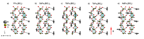
Regarding magnetic ordering, several interesting features are present in these materials. Previous measurements of magnetization Popova et al. (2007a), specific heatVasiliev et al. (2006) and other techniques like Mössbauer Hinatsu et al. (2003) spectroscopy and infrared absorption spectroscopy Chukalina et al. (2004) have revealed a second order antiferromagnetic (AFM) ordering transition of the iron sub-lattice at low temperatures (in the range K to 40 K). The orientation of the Fe moments depends on the rare-earth ion present in the structure. More specifically, at low temperature ( K) the Fe moments lie within the planeRitter et al. (2008); Fischer et al. (2006); Popova et al. (2010) for the Y and Nd based compounds, while for the Gd and Tb based they are parallel to the -direction (figure 1c). Furthermore, a first order magnetic phase transition is present in the Tb, Dy and Gd compounds, where the antiferromagnetically ordered iron moments undergo a spin flop from the easy axis state along the -direction to an easy plane one along the plane when a magnetic field along the -axis is applied at low temperature.Balaev et al. (2003); Popova et al. (2007a) In the case of the Fe spin flop is accompanied by a reconfiguration of the Tb moments from an antiparallel to a parallel arrangement (cf. Fig. 1d)Popova et al. (2007a); Ritter et al. (2007). Interestingly, in the case of there is also a temperature-driven reorientation of the Fe moments from -axis orientation to an -plane one, which occurs already in zero magnetic field at K. Here, the Gd moments are polarized along the axis by a biasing internal magnetic field created as a result of the Fe3+-Gd3+ exchange interaction.Pankrats et al. (2004); Yen et al. (2006) The resulting spin structure is sketched in figure 1b.
Recently and have been reported to exhibit a significant magneto-dielectric couplingZvezdin et al. (2005); Zvezdin et al. (2006a). For electric polarization to appear, small distortions or displacements of the atoms from their symmetry position are necessary. Therefore for the magnetically induced polarization present in these samples, a lattice distortion is expected which has not yet been seen experimentally. Magnetostriction measurementsKrotov et al. (2006); Zvezdin et al. (2006a) have shown a clear relation between lattice and magnetoelectric properties, but a proper description of the lattice distortions that produce the observed polarization is still lacking. In recent neutron scattering investigations which confirm the afore described spin structures, no new information is obtained regarding structural displacements which would explain the observed electric polarization, mainly due to the low q resolution of neutrons as compared to x-rays. Moreover it is not clear if the observed superstructures are purely magnetic or also structural. In this respect detailed x-ray diffraction studies are necessary to elucidate small structural and magnetic features.
In this paper we present a comprehensive hard x-ray scattering study on with RGd, Tb, Nd and Y in order to better understand the structural and magnetic properties of the material. Our data reveal a weak superstructure reflection at , i.e., at the antiferromagnetic ordering vector seen in neutron scattering. This reflection is clearly correlated to an in-plane ordering of the Fe spins and – depending on the material – can thus be induced by an external magnetic field. Through a careful analysis of the dependence of this reflection we rule out that it is related to a distortion of the lattice and demonstrate its purely magnetic character. Detailed analysis of the integrated intensities of the Bragg and superlattice reflections, together with their scattering cross section, allows us to determine the size of the spin component of the magnetic moments which are perpendicular to the scattering plane and their relative orientation with respect to the hexagonal basal plane. Moreover, in the earlier reported low-symmetry structural phase we observe additional reflections at that violate the diffraction conditions of and thus are suggestive of an overlooked symmetry reduction when indexing the crystal structure, or the appearance of a structural distortion that induces a lattice modulation.
The paper is organized as follows: In section II a short introduction into x-ray magnetic scattering (XMS) is given followed by a discussion of the non-resonant scattering cross section of x-rays by magnetic materials at high photon energies, in the frame of our experimental setup. Experimental details are given in section III, while the results of the observations and their discussion are presented in section IV. This section is divided in two parts. One concerns the structural phase transition while the second part focuses on the magnetic ordering of the system, which causes a superlattice peak with Miller indices (0,0,1.5). The nature of which is demonstrated to be magnetic. Finally the work is summarized in section V.
II X-ray magnetic diffraction
Neutron diffraction has been, since the determination of the magnetic structure of MnO by Shull and coworkersShull et al. (1951), the primary tool for revealing the magnetic structure of magnetic materials. The main reason for this is the direct interaction between the neutron dipolar moment with the atomic magnetic moment of the sample. The cross section of this is comparable with the neutron-nuclei interaction, and thus explains comparable intensities of magnetic and nuclear reflections. On the other hand the intensity of an x-ray beam scattered by unpaired electrons in a sample is much smaller than pure charge scattering by a significant factorBlume (1985) as is demonstrated in the following equation:
| (1) |
with the number of magnetic electrons per atom, the number of electrons per atom. and are the magnetic and charge form factors, respectively. is the expectation value of the spin quantum number and and are the photon energy and electron’s rest mass, respectively. Apart from using resonant x-ray magnetic scattering (RXMS), which has advanced to become a very successful tool in the past yearsPaolasini et al. (2001); Nandi et al. (2008); Mo et al. (2008), one can overcome this difference in intensities only by using high brilliance, collimated and polarized sources like synchrotron radiation. This so-called non-resonant x-ray magnetic scattering (NRXMS) has only rarely been applied in the past years to study magnetic structuresBergevin and Brunel (1972); Brückel et al. (1996); Strempfer et al. (1996); Chatterji et al. (2004). However, compared to neutron scattering this technique offers some advantages since it is possible to separate spin and angular momenta from the scattered intensities. This intriguing property is associated with the matrix elements in the non-resonant cross sectionBlume and Gibbs (1988), which depend in different ways on the scattering geometry, photon energy and initial and final polarization states of the x-ray beam, as will be discussed in detail below.
II.1 The Non-Resonant X-ray Magnetic Scattering Cross Section
Out of various discussions of the non-resonant cross section of x-ray magnetic scatteringBlume and Gibbs (1988); Brückel et al. (1996); Strempfer et al. (1996) we follow the one of Brückel et al.Brückel et al. (1996). The elastic cross section for scattering of photons with initial incident polarization and final polarization can be written as
| (2) |
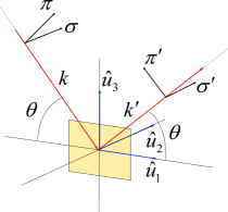
where is the electron classical radius and is the Compton length of the electron. The matrices and describe the polarization dependence of the magnetic and charge scattering amplitudes, respectively. Figure 2 depicts the reference frame for the diffraction experiments performed in this work. Here, and refer to the incoming and outgoing x-ray beams respectively. The and vectors correspond to polarization perpendicular and parallel to the scattering plane. Finally, , and are the unitary vectors of the reference frame as defined in ref. Brückel et al., 1996. Note that is parallel to , which defines the scattering vector. If we only consider pure magnetic diffraction (), in the frame sketched in figure 2, and taking into account that our diffraction measurements were performed with -polarized incoming photons (see figure 2) at an energy of 100 keV ( Å). The matrix that describes the magnetic scattering amplitude reduces to Strempfer et al. (1996):
| (3) |
Where is the projection of the spin moment in the direction. This means that under high energy diffraction conditions, non-resonant magnetic reflections can be observed at positions of the reciprocal space where no charge scattering is present, if the spin moments of the atoms have a component perpendicular to the x-ray scattering plane. Note that the incoming/outgoing beam polarization plays no role for the analysis of the diffracted intensities. Therefore, the cross section of a pure magnetic reflection under the above discussed conditions has the following form:
| (4) |
III Experimental details
Single crystals of with R = Y, Nd, Gd, Tb have been grown using a -based fluxBalaev et al. (2003); Bezmaternykh et al. (1984) and characterized by specific heat and magnetic susceptibility measurements using a physical property measurement system and a SQUID magnetometer, respectively, from Quantum DesignTristan et al. (2007); Popova et al. (2010, 2007b, 2007a). High energy x-ray diffraction experiments were performed at beamline BW5 in Hamburg (HASYLAB at DESY) using an incident photon energy of 100 keV. The penetration depth of the x-rays at this energy is of the order of millimeters, enabling the study of bulk properties of large single crystals. The triple-axis diffractometer is equipped with a cryomagnet mounted on a double-tilt table with eulerian geometry and a solid state Ge detector (energy resolution of 500 eV at 100 keV)Bouchard et al. (1998). The sample was mounted inside the cryomagnet where temperatures down to 1.5 K can be reached and horizontal magnetic fields up to 10 T can be applied parallel and perpendicular to the scattering vector. The samples were aligned with the horizontal scattering plane being perpendicular to the plane of the samples. Magnetic fields up to 8 T were applied along the -direction and perpendicular to it.
The full integrated intensity of the observed reflections was extracted from the raw data by performing reciprocal lattice scans (e.g -scans) at a given reflection, followed by scans along the -direction at the maximum intensity of the former scan. The and -scans were made extended to the peak sides until a constant background was reached. The scans were fitted using a Gaussian profile.
IV Results and discussion
IV.1 Structural Transition at TS
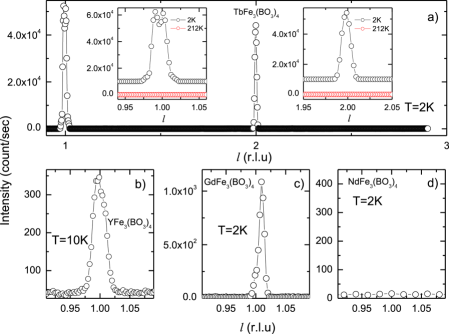
In order to search for superlattice reflections in our diffraction experiments, we performed overview scans along with and along with at various temperatures. Figure 3a shows a representative example of the -scan for at low temperature (2 K) and at 212 K (Figure 3a insets), i.e., in the reported and symmetries of the crystal structure, respectively. Along this direction, the reflection conditions of both symmetries are identical, viz. () with integer . As can be seen in the figure, the reflection conditions for the high symmetry space group are perfectly fulfilled. Interestingly, this is not the case for the low temperature data, where clear superlattice peaks at ( and ( are observed, thus violating the reflection conditions of the space group.
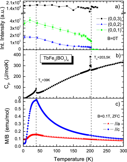
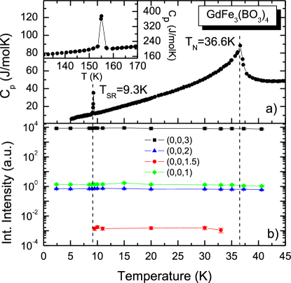
We have studied the temperature dependence of these two unexpected reflections in comparison with the Bragg peak in detail as is shown in Fig. 4. The data shown in part a) of the figure clearly reveal that the new superlattice peaks appear abruptly at the structural transition temperature K which is accompanied by a pronounced peak in the specific heat (cf. Fig. 4b). Upon lowering the temperature, both reflections persist down to the lowest investigated temperature, where both peak intensities gradually increase without significant further changes, suggesting a stabilization of the structural distortion. The compound undergoes antiferromagnetic order at K as is evidencedPopova et al. (2007a) by a further anomaly in the specific heat and a rapid decrease of the magnetic susceptibility (cf. Fig. 4c). However, no significant change of the peak intensities occurs when crossing through this temperature. The occurrence of these new, in the symmetry forbidden reflections at is not a particular feature of , but it is a common feature of all compounds investigated in this study that experience a structural transition towards a symmetry lower than . This can be clearly seen in the panels b, c, and d of Fig. 3, which depict -scans around for the Y, Gd, and Nd pendants of . Indeed, pronounced peaks centered around ) are observed for both the Y and Gd based compounds but not for .
Our observation clearly implies that materials undergo a symmetry reduction at which results in a low temperature phase that is inconsistent with the space group assigned so far. The new reflections at have not been reported earlier, which is probably due to the fact that their intensities are about four orders of magnitude weaker than that at and thus can easily be overlooked unless the experiment relies on single crystals and x-rays from high brilliance sources like synchrotron radiation which probe the crystal’s bulk.
No possible symmetry subgroup of the space group yields conditions that satisfy the presence of the and reflections. There are only two possible reasons that could explain them. The first possibility is related to the spiral chains of octahedra which run along the -axis and yield the three-fold screw axis () symmetry feature. The presence of the reflection can be interpreted as a superlattice reflection resulting from a slight deviation of the Fe atom positions from the symmetry positions generated by the screw axis, e.g., by a slight displacement in the vertical direction from the symmetry position, resulting in a modulation that requires a tripling of the unit cell in order to fully describe the symmetry of the structure. The second possible explanation is based on a special case of multiple diffraction. More precisely, the symmetry reduction to could, in principle, allow multiple scattering by planes in other orientations within the crystal, with a condition that is not possible at the higher symmetry. In general, multiple scattering requires special geometry conditions which are already violated at small changes of the azimuth angle. In order to discard multiple scattering events, azimuth scans on the reflection were performed with the result that the reflection remains observable even at azimuth angles larger than 90∘. Since multiple scattering is rapidly suppressed by rotating the crystal along the azimuth direction, multiple scattering can be disregarded as the origin of reflections. Our data thus implies that the superlattice reflections come from small structural distortions, as previously discussed, and not from multiple scattering events.
Coming back to , this compound shows the largest magnetic induced electric polarization measured among the ferroborates. Since in this compound no structural transition is present, i.e. no reflections are observed (cf. Fig. 3d). Thus, we can easily rule out the distortions responsible for these reflections as the origin of the electric polarization present in some of these compounds.
IV.2 Superlattice reflections in the antiferromagnetic phase
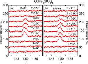
Upon close inspection of the scans in the antiferromagnetically ordered phase () we observe further weak superlattice reflections at with an intensity about six to seven orders of magnitude smaller than the main reflection. A representative example for this reflection is shown in Fig. 5a for the case of . Judging from the Miller indices of this reflection, the ordering of the magnetic ions generates an additional symmetry (super-lattice) which is commensurate with the chemical structure and involves a doubling of the unit cell along the -direction. As can be seen in the data for , the peak gradually emerges from the background a few degrees below K and persists below 30 K with constant intensity down to 10 K. Upon cooling further the peak abruptly vanishes and remains absent at K. Fig. 6 shows the temperature dependence of the peak intensity in comparison with the specific heat. Obviously, the disappearance of the peak occurs exactly at the spin reorientation transition at K where the Fe-spins turn from an easy-plane configuration in to an easy-axis one along the -axis. This suggests that the superstructure which gives rise to the new superlattice reflections is related to the in-plane orientation of the iron spins.
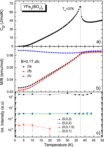
This conjecture is corroborated by further investigations on the Y, Nd and Tb based compounds which exhibit in-plane Fe spin order (Y, Nd) and -axis oriented moments (Tb), respectively. Fig. 7 shows the temperature dependence of the specific heat, magnetic susceptibility and diffraction peak intensities for . The onset of antiferromagnetic order of the iron spin with -orientation below K can clearly be inferred from the strong peak in the specific heat at this temperature and the strong decrease of the in-plane magnetic susceptibilitiesHinatsu et al. (2003). Similarly as in , the peak emerges below . We point out, however, that the peak could be resolved only below 20 K.
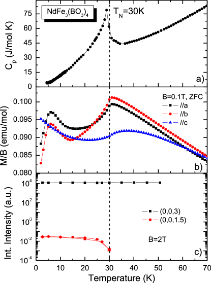
We find a very similar result for as is shown in Fig. 8. The magnetic ordering temperature K is somewhat reduced in this material as compared to the previous discussed cases. As in , the spin configuration is in-planeFischer et al. (2006) as is signaled by the magnetic susceptibility shown in Fig.8b and a superlattice reflection at is observed throughout the antiferromagnetic phase (cf. Fig.8c). Note that in contrast to the other compounds the crystal symmetry remains down to lowest temperature.
In contrast to these previous cases, in the Fe moments are parallel to the -axis and no superlattice reflection is present in the whole zero magnetic field phase at K. Thus, the afore discussed conjecture of in-plane oriented Fe-moments as the required condition for observing the superlattice peaks is further substantiated.
IV.3 Field dependence of the (0,0,1.5) reflection
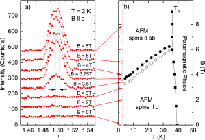
In order to manipulate the Fe spin orientation and thereby investigate the field dependence of the reflection we applied external magnetic fields. In , which exhibits AFM order with as the easy axis in zero field, the metamagnetic transition which occurs upon the application of an external magnetic field parallel induces an in-plane configuration of the iron spinsPopova et al. (2007a). Fig. 9b reproduces the magnetic phase diagram of this compound from Ref. Popova et al., 2007a which allows to elucidate the temperature and magnetic field dependence of the metamagnetic transition. Fig. 9a shows that at low temperature K the peak emerges from the background at magnetic fields T, i.e., as soon as the Fe moments are oriented in-plane, it quickly gains intensity up to saturation at higher magnetic fields (see Fig. 10b). The peak width does not change when increasing the field, supporting the picture of a spin-flop where there is no significant change of the spin correlation length, but only of the spin direction. The inset in figure 10b shows the intensity of this peak as a function of temperature at a fixed external field of T parallel to , which corresponds to a horizontal cut through the phase diagram in Fig. 9. As can be seen in the figure, the peak intensity is constant at K, rapidly decreases at higher and eventually vanishes at K. Note, that upon crossing this temperature the Fe-moments reorient from the in-plane to the parallel configuration of the AFM phase.
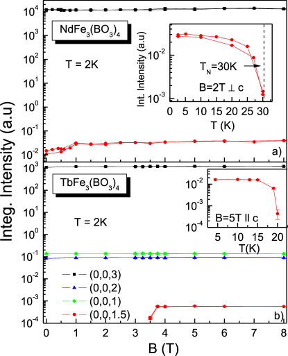
We have performed a similar measurement also for . As has been discussed already above, in zero magnetic field, the reflection appears only in the temperature range between and (Figure 6b). According to Yen et al.Yen et al. (2006) the spin reorientation temperature decreases if a magnetic field parallel to the direction is applied. As can be seen in Fig. 6b for the case of T, the downshift of also leads to a shift of the lowest temperature at which the reflection appears. To be specific, at the applied magnetic field the reflection is well resolved at K, i.e. in perfect agreement with the phase diagram reported by Yen et al Yen et al. (2006).
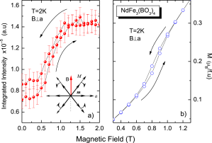
Both examples where the superlattice reflection is induced by an external magnetic field unambiguously demonstrate that there is a clear one-to-one correlation between this reflection and the in-plane orientation of the Fe spins. In the following we point out that even more subtle changes of the magnetic structure have an impact on the intensity of the reflection. Figure 10a shows the integrated intensity of the magnetic reflection as a function of magnetic field for with the magnetic field oriented in-plane. It can be seen that the magnetic peak intensity increases with increasing the field, until it reaches saturation at T. Results of a detailed measurement in this field range are shown in figure 11a and reveal that the peak intensity exhibits a steep increase at T, while it is constant at lower and higher fields. Interestingly this increase of peak intensity coincides with an increase of magnetization as is shown in Fig. 11b. The small jump in magnetization is the signature of a spin flop of both Fe and Nd moments, along a direction perpendicular to the external field within the basal planeVolkov et al. (2007).
IV.4 Discussion
The magnetic structure of (, Nd, Tb) has been studied in a number of different neutron diffraction experimentsFischer et al. (2006); Ritter et al. (2007, 2008). Depending on the compound, either a spin spiral () propagating along the axisFischer et al. (2006) or a Néel stateRitter et al. (2007, 2008) ( and ) have been inferred from the data. In all cases commensurate magnetic superlattice reflections occur at , i.e. the magnetic supercell is doubled along the axis. Hence, at first glance two possible origins of the x-ray superlattice reflections should be considered. Firstly, the observed superlattice reflections could be of magnetic nature and thus represent the x-ray pendant of the magnetic reflections seen in neutron scattering. Secondly, the superlattice reflections could result from a weak structural distortion that is imposed by the magnetic ordering. An appealing scenario for the latter which reasonably explains the observed correlation between the occurrence of the superlattice reflections and the orientation of the Fe-spins is a magnetic spiral state which propagates along the -axis (as is concluded from neutron data for Fischer et al. (2006)) and thus could in principle lead to a structural distortion following the spin spiral. This spiral state (including the assumed lattice distortion) requires the Fe moments or a component of them to lie in the -plane and thus it has to vanish as soon as the Fe moments are fully oriented along .
On the other hand, there are compelling reasons to rationalize the superlattice reflection in terms of purely magnetic scattering. The Bragg angle for this reflection at keV is , i.e. close to . As discussed in section II.1, the cross section for magnetic scattering under this experimental conditions allows to observe magnetic scattering when the spins of the unpaired electrons have a component perpendicular to the scattering plane (eq. 3). In our experimental setup this is indeed the case if the iron spins lie in the plane of the sample. Thus, the surprising dependence of the peak intensity on the spin orientation is naturally explained without further assumptions. Moreover, the intensity of this reflection is around seven orders of magnitude weaker than the Bragg peak, which is just the expected order of magnitude for magnetic reflections (cf. equation 1). Thus it seems more reasonable to assign a magnetic origin to the superlattice reflection.
q and azimuth dependence of the magnetic reflection

In order to verify the latter conclusion we have performed measurements of the q-dependence of the intensity of both the structural Bragg reflections and of the reflections, where we studied as a representative case (see Fig. 12). As a function of q, the measured intensity of the structural Bragg reflections (filled triangles) evolves as it is expected from structure factor calculations (open triangles). One can see that even at large q values the charge reflections are still strong. A much faster decrease of intensity with increasing q is expected for magnetic reflections as is shown in the figure by the open diamonds, which agrees well with the observed intensities of the reflections and thus allows to unambiguously identify the peak as magnetic. 111The charge and magnetic form factors were calculated using the tabulated magnetic and charge form factors reported in the international tables of crystallographyWilson ((1992). The atom positions were obtained from single crystal x-ray diffraction (SCXRD) measurements performed at T=100K, using a Bruker Kappa APEX II diffractometer with Mo radiation. The data were refined using the program SHELXSheldrick (1990). The magnetic structure factor was calculated taking into account only the Fe atoms, since these are the ones which have the major contribution to the magnetization, and assuming .
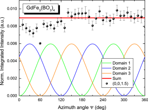
In principle, the peak intensity at should depend on the azimuth angle if an easy axis exists when the Fe spins lie within the plane. Measurements at different azimuth angles at are presented in Fig. 13. Since the integrated intensity of the magnetic peak shows a constant azimuth dependence, only two possible scenarios are in agreement with the experiment. The first possible interpretation involves an equally populated domain structure, where the three equivalent domains in the basal plane are rotated 120∘ relative to each other. Figure 13 shows the expected signal for the three different domains and the red line refers to the summation of the three domain signals. The second possible reason of such azimuth dependence is the formation of a spin spiral as suggested from neutron diffraction dataFischer et al. (2006).
It is interesting to point out in this regard the afore described effect of an external magnetic field on the reflection where the field was applied in-plane. Since in our setup the field direction lies in the scattering plane, a spin flop of the iron moments will definitely manipulate the number of spins perpendicular to the scattering plane. More specifically in , following a spin model suggested by Volkov et al,Volkov et al. (2007) one should expect three equivalent easy directions of magnetization in the basal plane (see inset in fig. 11a). The applied magnetic field causes the spins to flop into a direction perpendicular to the applied field, i.e perpendicular to the x-ray scattering plane. From equation 3 it is clear that an increase of the spin component perpendicular to the scattering plane enlarges the magnetic scattering cross section and therefore yields an increase of the intensity. Figure 11a actually shows the enhancement of the magnetic intensity due to the rotation of the magnetic moments along the scattering plane normal.
Correlation length of the magnetic domains
The width of the magnetic reflection is around twice the width of the nearest Bragg reflection, as shown by the dashed lines in figure 9a for . This suggests that the correlation length, or size of the magnetic domains within the crystal, has a finite size. Experimentally, the measured diffracted signal is a convolution of the experimental resolution function and the intrinsic diffracted signal from the crystal. Hence, the measured signal can be expressed as:
| (5) |
Where denotes the convolution of the experimental resolution function and the intrinsic signal . If we consider the Gaussian fit profile of the (0,0,3) Bragg reflection as our experimental resolution function where FWHM(0,0,3) = 0.0072(1) r.l.u., an estimation of the intrinsic magnetic diffracted signal can be obtained by a deconvolution from the measured signal. As the measured signal can also be expressed by a Gaussian, thus the intrinsic function is also a Gaussian with full width at half maximum (FWHM) equal to:
| (6) |
After deconvolution, the correlation length of the magnetic domains along the direction was estimated assuming a perfect crystal with no strain, assumption supported by the small crystal mosaicity, 0,0060(1)∘, determined from the 2 scan of the (0,0,3) Bragg reflection. For all compounds we find (cf. table 1 for details). The correlation length was calculated using the following relation:
| (7) |
| Sample | (Å) | |
|---|---|---|
| 107 33 | T=5 K | |
| 99 5 | T=10 K | |
| 101 1 | T=2 K, B 3.5 T | |
| 93 2 | T=2 K, B=0 | |
| 104 2 | T=2 K, B 2 T |
The magnetic structure factor and the spin-moment in GdFe3(BO3)4
Finally, according to equation 4 it is possible to determine the size of the component of perpendicular to the scattering plane from the measured integrated intensity of a magnetic reflection. In the kinematical approximation, the magnetic and charge reflectivity ratio of a crystal in a Laue symmetry has the following form:
| (8) |
, , and are the measured integrated intensities of the magnetic and charge reflections, and the magnetic and charge structure factors, respectively. and are the Bragg angles of the magnetic and charge scattering, is the interatomic spacing of the magnetic reflections and is a correction factor that compensates for the three equally populated domains in which the magnetic moment lies in the hexagonal basal plane. The direct measurement of the intensity of the Bragg peak is not possible since the strong intensity saturates the detector. It is necessary to measure this peak at different radiation absorbers and finally extrapolate to absorber 0. Using the calculated value of and knowing that only the iron atoms contribute to the magnetic scattering in the sample, the solution of equation 8 for yields an estimated value of . Since this values is a projection of along the scattering plane normal, which coincides with the plane as discussed before, one can calculate the angle between the iron moments and the basal plane. Taking as reported from magnetization measurementsYen et al. (2006), this angle is , which is in close agreement with the angle found by resonant scattering experimentsMo et al. (2008) which is around . Deviation from this values could arise from experimental restrictions, since the determination of the primary intensity of the (0,0,3) reflection is indirect and also that the weakness of the magnetic intensity can bring some systematic error while data acquisition.
V Summary
Structural and magnetic properties on compounds of the form (, Tb, Nd and Y) have been studied by means of high energy x-ray diffraction. Due to the high energy photons used during the experiment, NRXMS could be observed on all the compounds at temperatures below the magnetic order temperature when the AFM vector lies in the plane. The study of the magnetic reflection as a function of temperature and applied magnetic field shows the different metamagnetic transitions such as spin flops and spin reorientation transitions in , and . Moreover NRXMS allowed us to corroborate the magnetic structures obtained from neutron scattering experiments. Detailed analysis of the magnetically diffracted intensities as a function of magnetic field and azimuth angle in and respectively, suggests that the magnetic moments of the Fe ions are aligned in the crystallographic axis, leading to a domain structure formation since there are three equivalent directions in the hexagonal basal plane. For we extracted an out-of-plane angle of for the iron moments and for all the compounds, a correlation length of the magnetic domains of 100 Å was estimated.
Furthermore, we observed the presence of new superlattice reflections at . These suggest that the symmetry of the crystal has not been properly assigned, as these reflections violate the reflection conditions for the until now accepted space group.
VI Acknowledgments
This work was supported by the Deustche Forschungsgemeinschaft, through the Forschergruppe FOR520 (grant HE3439/6) and HASYLAB at the Deutsches Elektronen-Synchrotron (DESY).
The authors would like to acknowledge Dr. Sergio Valencia and Dr. Ralf Feyerherm from HMI Berlin and specially to Dr. Jörg Strempfer from HASYLAB at DESY in Hamburg for valuable discussions.
References
- Vasiliev et al. (2006) A. Vasiliev, E. Popova, I. Gugim, L. Bezmaternykh, and Z. Hiroi, J. Magn. Magn. Mat. 300, e382 (2006).
- Tristan et al. (2007) N. Tristan, R. Klingeler, C. Hess, B. Büchner, E. Popova, I. Gudim, and L. Bezmaternykh, J. Magn. Magn. Mat. 316, e621 (2007).
- Popova et al. (2007a) E. Popova, D. Volkov, A. Vasiliev, A. Demidov, N. Kalkova, I. Gudim, L. Bezmaternykh, N. Tristan, Y. Skourski, B. Büchner, et al., Phys. Rev. B 75, 224413 (2007a).
- Kadomtseva et al. (2005) A. M. Kadomtseva, Y. F. Popov, S. S. Krotov, G. P. Vorob’ev, E. A. Popova, A. K. Zvezdin, and L. N. Bezmaternykh, Low Temperature Physics 31, 807 (2005).
- Krotov et al. (2006) S. Krotov, A. Kadomtseva, Y. Popov, G. Vorobev, A. Kuvardin, K. Kamilov, L. Bezmaternykh, and E. Popova, J. Magn. Magn. Mat. 300, e426 (2006).
- Fausti et al. (2006) D. Fausti, A. A. Nugroho, P. H. M. van Loosdrecht, S. A. Klimin, M. N. Popova, and L. N. Bezmaternykh, Phys. Rev. B 74, 024403 (2006).
- Vasiliev and Popova (2006) A. Vasiliev and E. Popova, Low Temp. Phys. 32, 735 (2006).
- Yen et al. (2006) F. Yen, B. Lorenz, Y. Y. Sun, C. W. Chu, L. N. Bezmaternykh, and A. N. Vasiliev, Phys. Rev. B 73, 054435 (2006).
- Zvezdin et al. (2005) A. Zvezdin, S. Krotov, A. Kadomtseva, G. Vorobev, Y. Popov, A. Pyatakov, L. Bezmaternykh, and E. Popova, JETP Lett. 81, 272 (2005).
- Zvezdin et al. (2006a) A. K. Zvezdin, G. P. Vorobev, A. M. Kadomtseva, Y. F. Popov, A. P. Pyatakov, , L. N. Bezmaternykh, A. V. Kuvardin, and E. Popova, JETP Letters 83, 509 (2006a).
- Zvezdin et al. (2006b) A. Zvezdin, A. Kadomtseva, S. Krotov, A. Pyatakov, Y. Popov, and G. Vorob’ev, Journal of Magnetism and Magnetic Materials 300, 224 (2006b), ISSN 0304-8853, the third Moscow International Symposium on Magnetism 2005.
- Jouber et al. (1968) J.-C. Jouber, W. White, and R. Roy, J. Appl. Cryst 1, 318 (1968).
- Popova et al. (2008) E. A. Popova, N. Tristan, A. N. Vasiliev, V. L. Temerov, L. N. Bezmaternykh, N. Leps, B. Buechner, and R. Klingeler, The European Physical Journal B - Condensed Matter and Complex Systems 62, 123 (2008).
- Klimin et al. (2005) S. Klimin, D. Fausti, A. Meetsma, L. Bezmaternykh, P. van Loosdrecht, and T. Palastra, Acta Cryst. 61, 481 (2005).
- Hinatsu et al. (2003) Y. Hinatsu, Y. Doi, K. Ito, M. Wakeshima, and A. Alemi, J. Solid State Chem. 172, 438 (2003).
- Chukalina et al. (2004) E. P. Chukalina, D. Y. Kuritsin, M. N. Popova, L. N. Bezmaternykh, S. A. Kharlamova, and V. L. Temerov, Phys. Lett. A 322, 239 (2004).
- Ritter et al. (2008) C. Ritter, A. Vorotynov, A. Pankrats, G. Petrakovskii, V. Temerov, I. Gudim, and R. Szymczak, Journal of Physics: Condensed Matter 20, 365209 (9pp) (2008).
- Fischer et al. (2006) P. Fischer, V. Pomjakushin, D. Sheptyakov, L. Keller, M. Janoschek, B. Roessli, J. Schefer, G. Petrakovskii, L. Bezmaternikh, V. Temerov, et al., Journal of Physics: Condensed Matter 18, 7975 (2006).
- Popova et al. (2010) E. A. Popova, A. N. Vasiliev, V. L. Temerov, L. N. Bezmaternykh, N. Tristan, R. Klingeler, and B. Buechner, Journal of Physics: Condensed Matter 22, 116006 (2010), URL http://stacks.iop.org/0953-8984/22/i=11/a=116006.
- Balaev et al. (2003) A. D. Balaev, L. N. Bezmaternykh, I. A. Gudim, V. L. Temerov, S. G. Ovchinnikov, and S. A. Kharlamova, J. Magn. Magn. Mat. 258-259, 532 (2003).
- Ritter et al. (2007) C. Ritter, A. Balaev, A. Vorotynov, G. Petrakovskii, D. Velikanov, V. Temerov, and I. Gudim, Journal of Physics: Condensed Matter 19, 196227 (2007).
- Pankrats et al. (2004) A. I. Pankrats, G. A. Petrakovskii, L. N. Bezmaternykh, and O. A. Bayukov, Journal of Experimental and Theoretical Physics 99, 766 (2004).
- Shull et al. (1951) C. G. Shull, W. A. Strauser, and E. O. Wollan, Phys. Rev. 83, 333 (1951).
- Blume (1985) M. Blume, Journal of Applied Physics 57, 3615 (1985).
- Paolasini et al. (2001) L. Paolasini, S. D. Matteo, C. Vettier, F. de Bergevin, A. Sollier, W. Neubeck, F. Yakhou, P. A. Metcalf, and J. M. Honig, Journal of Electron Spectroscopy and Related Phenomena 120, 1 (2001), ISSN 0368-2048.
- Nandi et al. (2008) S. Nandi, A. Kreyssig, L. Tan, J. W. Kim, J. Q. Yan, J. C. Lang, D. Haskel, R. J. McQueeney, and A. I. Goldman, Physical Review Letters 100, 217201 (2008).
- Mo et al. (2008) H. Mo, C. S. Nelson, L. N. Bezmaternykh, and V. T. Temerov, Physical Review B 78, 214407 (2008).
- Bergevin and Brunel (1972) F. D. Bergevin and M. Brunel, Physics Letters A 39, 141 (1972).
- Brückel et al. (1996) T. Brückel, M. Lippert, T. Köhler, J. R. Schneider, W. Prandl, V. Rilling, and M. Schilling, Acta Crystallographica Section A 52, 427 (1996).
- Strempfer et al. (1996) J. Strempfer, T. Brückel, U. Rütt, J. R. Schneider, K.-D. Liss, and T. Tschentscher, Acta Crystallographica Section A 52, 438 (1996).
- Chatterji et al. (2004) T. Chatterji, K. Liss, T. Tschentscher, B. Janossy, J. Strempfer, and T. Brueckel, Solid State Communications 131, 713 (2004).
- Blume and Gibbs (1988) M. Blume and D. Gibbs, Phys. Rev. B 37, 1779 (1988).
- Bezmaternykh et al. (1984) L. N. Bezmaternykh, V. G. Mashchenko, N. A. Sokolova, and V. L. Temerov, Journal of Crystal Growth 69, 407 (1984).
- Popova et al. (2007b) E. A. Popova, N. Tristan, C. Hess, R. Klingeler, B. Büchner, L. N. Bezmaternykh, V. L. Temerov, and A. N. Vasiliev, Journal of Experimental and Theoretical Physics 105, 105 (2007b).
- Bouchard et al. (1998) R. Bouchard, D. Hupfeld, T. Lippmann, J. Neuefeind, H.-B. Neumann, H. F. Poulsen, U. Rütt, T. Schmidt, J. R. Schneider, J. Süssenbach, et al., Journal of Synchrotron Radiation 5, 90 (1998), URL http://dx.doi.org/10.1107/S090904959701457X.
- Volkov et al. (2007) D. V. Volkov, A. A. Demidov, and N. P. Kolmakova, Journal of Experimental and Theoretical Physics 104, 897 (2007).
- Wilson ((1992) A. Wilson, ed., Int. Tables of Cryst. Vol C (The International Union of Chrystallography, (1992)).
- Sheldrick (1990) G. M. Sheldrick, Acta Crystallographica Section A 46, 467 (1990).