On the incompatibility of strains and its application to mesoscopic studies of plasticity
Abstract
Structural transitions are invariably affected by lattice distortions. If the body is to remain crack-free, the strain field cannot be arbitrary but has to satisfy the Saint-Venant compatibility constraint. Equivalently, an incompatibility constraint consistent with the actual dislocation network has to be satisfied in media with dislocations. This constraint can be incorporated into strain-based free energy functionals to study the influence of dislocations on phase stability. We provide a systematic analysis of this constraint in 3D and show how three incompatibility equations accommodate an arbitrary dislocation density. This approach allows the internal stress field to be calculated for an anisotropic material with spatially inhomogeneous microstructure and distribution of dislocations by minimizing the free energy. This is illustrated by calculating the stress field of an edge dislocation and comparing it with that of an edge dislocation in an infinite isotropic medium. We outline how this procedure can be utilized to study the interaction of plasticity with polarization and magnetization.
pacs:
05.70.-a, 61.72.Lk, 63.70.+h, 75.85.+t, 81.30.KfI Introduction
Physical properties of solids are mainly determined by crystal defects. Their strain fields couple to the microstructure and thus often deteriorate the properties of the underlying perfect crystal. The coupling of point defects with microstructure can give rise to variation in the twin wall widths of ferroelastic martensites Lee et al. (2005). Similarly, dislocations through their long-range strain fields affect the spatial evolution of the microstructure and are typically responsible for shifts of the transformation temperature Sato et al. (1982); Miyazaki et al. (1986); Gröger et al. (2008). To guarantee phase stability, one needs to understand how the phase diagram changes as a function of the density of dislocations. This can be accomplished efficiently using the continuum theory of dislocations Kröner (1958); Kroupa (1962); Kosevich (1979) in which dislocations are viewed as sources of incompatibility of strains and stresses Teodosiu (1982); Kleinert (1989).
The concept of incompatibility of strains was used as a basis for the development of field dislocation mechanics Acharya (2001) and continues to serve as a template for the development of mesoscopic models of self-organization of dislocation networks Bakó (1999); El-Azab (2000); Zaiser et al. (2001); Limkumnerd and Sethna (2006). It has been readily incorporated within the Landau continuum approach to study spinodal decomposition mediated by dislocations Haataja and Léonard (2004) as well as the effects of dislocations on the stability of phases in martensites Gröger et al. (2008). These studies have been in two dimensions where only one incompatibility relation constrains the spatial variation of order parameter fields Kerr et al. (1999); Lookman et al. (2003). Analyses of the three-dimensional compatibility constraint, which guarantees integrability of the strain field in dislocation-free media, can be found in Malyi (1986); Borg (1990); Selvadurai (2000). In three dimensions, the compatibility constraint is represented by six equations whereas only three are required to make the strain field integrable Rasmussen et al. (2001). It has not been apparent how this reduction can be justified and this lack of understanding has led to conflicting statements about the mutual dependencies of these equations Andrianov and Awrejcewicz (2003). Nevertheless, a systematic analysis that examines the structure of the three-dimensional incompatibility constraint as applied to a finite density of dislocations, is lacking. This has not allowed for the generalization of two-dimensional models of plasticity to three dimensions. The primary objective of this paper is to provide a systematic analysis of the full set of six incompatibility equations assuming periodic boundary conditions and to show how they can be reduced to three incompatibility constraints that represent an arbitrary dislocation network. This makes it possible to develop strain-based free energies Barsch and Krumhansl (1984); Kartha et al. (1995) in 3D that describe the spatial evolution of the microstructure at the length and time scales that are not amenable to atomistic or continuum approaches.
The elastic free energy due to a distortion from a high symmetry parent phase to a lower symmetry product phase is typically written in terms of a finite number of order parameters that characterize this change. Thus, the transformation from a cubic symmetry to the tetragonal, orthorhombic or monoclinic symmetries involves symmetry-allowed invariants in the free energy, the mathematical structure of which is the same for all materials that undergo the same type of phase transition. Materials undergoing the same crystal symmetry change are distinguished by the coefficients of these invariants that reflect the temperature and pressure dependencies of elastic constants, martensitic strain at the transition or curvature of soft phonon modes that drive the transition. This is extremely valuable since a single formulation of the free energy then describes a large class of materials. In this paper, we consider the strain-based formulation of the Landau-Ginzburg functional Landau and Lifshitz (1986) for the cubic to tetragonal transformation that was developed by Barsch and Krumhansl Barsch and Krumhansl (1984) and successfully applied in a number of theoretical studies Bishop et al. (2003); Ahluwalia et al. (2006); Gröger et al. (2008).
II Incompatibility constraint
We begin by defining a set of six symmetry-allowed combinations of the components of the elastic strain tensor which can serve as order parameters to characterize the symmetry change from the parent (typically cubic) phase to an equal or lower symmetry phase. The free energy is then written in terms of these order parameters and its minimization yields the homogeneous ground state as well as spatial variations in the order parameter fields due to any inhomogeneities, such as gradient terms. However, in order to keep the deformed body continuous (i.e. without cracks), the components of the total distortion tensor cannot be independent ( is the symmetric elastic-plastic strain tensor and the antisymmetric tensor of elastic-plastic rotations). Instead, they satisfy the equation Kröner (1958) , where the total distortion is . Here, is the permanent plastic distortion of the lattice due to the spatially inhomogeneous distribution of dislocations. It is then customary to write , where is the Nye tensor that represents the density of infinitesimal Burgers vectors Nye (1953). However, the cohesive forces of the matter cause elastic relaxation of the lattice, . In order for the total distortion tensor to be curl-free, it follows that . This tensor is non-symmetric and its components, , correspond to a dislocation whose line direction is parallel to and the Burgers vector parallel to . Hence, the diagonal components of correspond to the three screw dislocations with their line directions parallel to the three axes, while the six off-diagonal components describe the density of the six variants of edge dislocations. Taking the symmetric part of the curl of yields the so-called incompatibility constraint
| (1) |
where is the incompatibility tensor.
When developing models of phase transformations based on strains, the condition (1) has to be enforced Kröner (1958). In components, Eq. (1) represents two sets of three equations,
| (2) |
where and . The comma means a partial derivative and no summation of the repeated indices is performed here. In two dimensions, only one equation is not satisfied trivially and this represents the constraint for the internal strains. The situation is more complicated in three dimensions since all six equations have to be enforced. However, only three equations are needed and the main problem is to find a rigorous way to reduce the six equations to three.
In order to find the minimum number of constraints for a spatial variation of the internal elastic strain field that complies with a given dislocation density, assuming periodic boundary conditions, we begin by writing (2) in k-space. In the augmented matrix representation, this linear system takes on a block-symmetric form
| (3) |
where tilde () denotes a Fourier image, and is the k-space vector. If no additional constraints on the components are supplied, this system of equations would be internally inconsistent. The three conditions that make this system consistent are obtained from the Bianchi identity which is only true for a permissible dislocation density, i.e. if dislocations do not begin or end inside the body. In order to gain insight into the structure of (3), let us begin by splitting the system into two sets of three equations each, where the first set is obtained from (3) by taking rows number 1-3 and the second set from rows number 4-6. Performing the row reduction on each of these subsystems separately converts them into the following forms:
| (4) |
where the matrices of both systems are given by
| (5) |
However, the right-hand sides of (4) are different:
| (6) |
It is important to emphasize that the right-hand side of the first system contains only the diagonal components of . If an edge dislocation is present, only is nonzero whereas . Similarly, the right-hand side of the second system contains only the off-diagonal components of . Hence, for a screw dislocation is nonzero whereas . Clearly, the first set of equations can be used to incorporate edge dislocations, while the second set incorporates screw dislocations. However, one cannot solve these systems to obtain the strain field in terms of the components of the incompatibility tensor . They only represent constraints that the internal strain field has to satisfy if a finite density of dislocations is present. It is also very important to emphasize that since the right-hand sides of these systems are different, the constraints imposed on strains by the two systems are in general different. Hence, we denote by and the total elastic strain fields due to all edge and screw dislocations, respectively. Because the two systems are linear, the superposition of the two sets yields
| (7) |
where is the Fourier image of the total elastic strain tensor. Eq. (7) represents a linear system of three incompatibility constraints whose right-hand side contains in general all components of the incompatibility tensor. Hence, in three dimensions (7) are three conditions the internal strain field has to satisfy due to the existence of an arbitrary distribution of the dislocation density. If these equations are written as constraints, i.e. and , one can write the free energy density for a ferroelastic material in k-space as
| (8) |
where is the k-space expression of the free energy density, the Lagrange multipliers, and the volume of the k-space. Recall that for two-dimensional problems, the sum in (8) contains only one term, namely that corresponding to , where is the direction of the (straight) dislocation line. However, in three dimensions, this sum contains three terms that impose the three conditions embodied in (7). The development above is completely general, applicable to any kind of displacive phase transformation and an arbitrary (but permissible) dislocation density. Below, we use this formulation to outline the development of a self-consistent mesoscopic model for a cubic to tetragonal transformation in which the microstructure is coupled to the density of dislocations.
III Cubic to tetragonal transition
We begin by defining a set of six order parameters (), one of which corresponds to a hydrostatic distortion, two to the change of shape from cubic to tetragonal, and three are shear components. The concrete expressions for these order parameters can be found in Barsch and Krumhansl (1984). Here, the primary order parameters are those that represent the tetragonal distortion of the lattice, while all others are secondary order parameters. If one considers the cubic structure as a reference phase of zero energy, then the strain energy density of a distorted phase relative to this reference structure can be written as . Since this is harmonic, its minimum corresponds to the reference cubic structure. In order to allow for a phase transition to occur, one augments the free energy by higher order terms of the primary order parameters that respect the cubic symmetry. Finally, the length scale is included by adding gradient terms of the primary order parameters. The free energy density is then written as , where is a vector of the six order parameters. Similarly, we can obtain an equivalent expression for the three incompatibility conditions in terms of the order parameters. The stationary order parameter fields corresponding to a fixed dislocation density (i.e. incompatibility field ), are then obtained by variational minimization of the free energy equivalent to (8). Since the components of the elastic strain tensor are defined in terms of the order parameters, the internal elastic strain field is straightforward to calculate. The conjugate stress field is then obtained at once using the Hooke’s law.
(a) (b)
(c)
Our objective in the following is to demonstrate how the internal strain field is disturbed when a single edge dislocation is present. It can be shown that without dislocations, the minimum of the free energy corresponds to a twinned microstructure with the normal parallel to the direction. Due to the rotational symmetry of the parent cubic lattice, we may consider that the normal of the martensite plate is parallel to . If we further consider a straight edge dislocation whose line direction is parallel to , all fields are functions of and but not of . This allows us to reduce the problem to the two dimensional plane strain case.
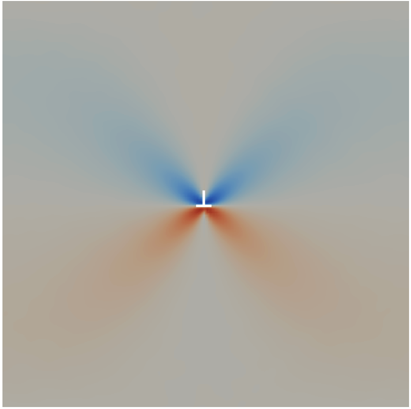
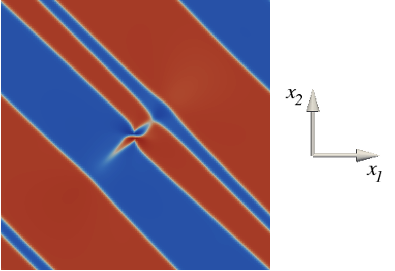
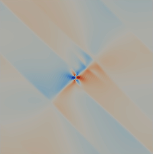
Let us now insert a edge dislocation into the middle of the block, as shown in Fig. 1a. Here, the Burgers vector of the dislocation is taken artificially as the edge length of one unit cell used to discretize the space in our simulation. Due to the periodic boundary conditions, this represents an array of straight edge dislocations whose line directions are parallel to and the Burgers vectors point in the positive direction. Hence, the only nonzero component of the Nye tensor is and the only nonzero component of the incompatibility tensor is . This incompatibility is incorporated into the free energy by the procedure explained above. Minimization of the free energy then yields the equilibrium internal strain field. This is represented using the order parameters . Since we are interested in the phase transformation from the parent cubic phase to the product tetragonal phase, we will be concerned with the spatial variation of , which is proportional to the deviatoric strain . This minimization was first performed above and Fig. 1a shows the calculated spatial variation of the order parameter field . If the dislocation was not present, the minimum of the free energy would correspond to the cubic phase (gray color). However, if the dislocation is present, the spatially homogeneous microstructure is frustrated by the strain field of the dislocation. One can imagine that the dislocation was created by sliding into the block an extra half-plane at which terminates in the middle of the block. Hence, the surrounding lattice at is under compression in the direction. Because and , the order parameter becomes negative and this corresponds to the blue region in Fig. 1a. Due to the termination of the extra half-plane at , the lattice at is under tension in the direction. Since and the order parameter is positive here and this gives rise to the red part of the butterfly shape in Fig. 1a. If the minimization of the free energy was performed below and the body was free of dislocations, the equilibrium field would represent a twinned microstructure in which the two tetragonal variants would be separated by twin boundaries of the cubic symmetry. As shown in Fig. 1b, the presence of the dislocation causes a local distortion of this twinned microstructure. This results in a misorientation of the direction of the tetragonal distortion and an emergence of curvature, both in the neighborhood of the dislocation and also farther away where the tip of the distortion meets another twin boundary. In addition to this distortion, the microstructure accommodates the dislocation as a part of the twin boundary. The distortion around the dislocation thus represents signatures of the dislocation in the order parameter field above and below . For distances large compared to the unit cell in the calculation, both fields in Figs. 1a,b approach those for the dislocation-free body above and below , respectively.
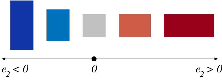
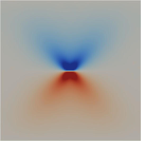
For completeness, we show in Figs. 2a-c and Figs. 2d-f the three components of the calculated internal stress field above and below , respectively. Here, red represents positive stresses, gray the unstressed regions, and blue negative stresses. Above , the stress field in Figs. 2a-c agrees qualitatively with that obtained from analytical expressions of the stress field around an edge dislocation in an infinite isotropic mediumHirth and Lothe (1982). Below , the stress field in Figs. 2d-f includes nonlocal interactions of the the stress field of the dislocation with the microstructure. No analytical expression for the stress field exists due to the complexity of the problem. As we showed already in Fig. 1b, an edge dislocation below is responsible for developing curvature in the system. This shows up in the stress field by local bending of the twin walls in the vicinity of the dislocation and reversals of the state of stress in the direction perpendicular to the twin wall.
Although the calculation above has been performed for one edge dislocation, this approach is completely general in that the right-hand side of (7) can represent an arbitrary dislocation network.
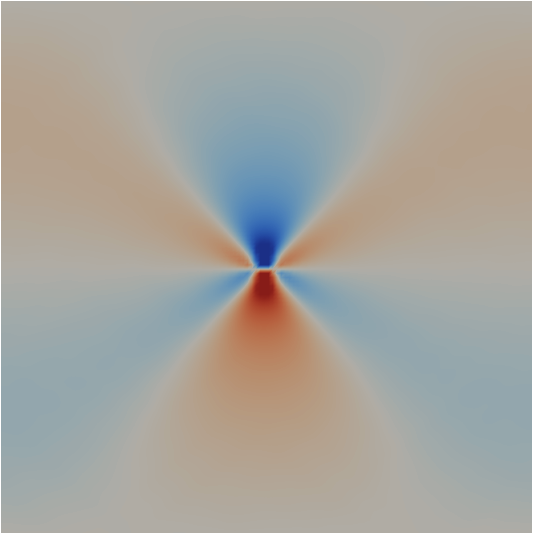
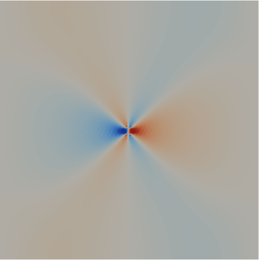
(a) (b) (c)
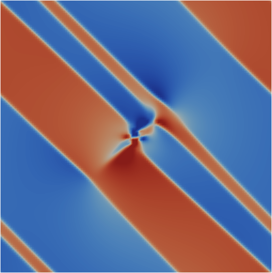
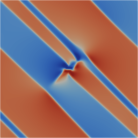
(d) (e) (f)
IV Generalization
The formalism developed above can be systematically extended to study the influence of dislocations on the physical properties of multiferroics. To describe piezoelectric/piezomagnetic materials in which polarization/magnetization is coupled to strain Ahluwalia et al. (2005), one typically begins by writing the Gibbs free energy density
| (9) |
where is a vector of order parameters and the Landau free energy density consistent with the symmetry of the underlying crystal structure. The second term in (9) represents the elastic strain energy density and the third term incorporates the (in)compatibility constraint derived earlier. The spontaneous strain is written as , where is the total elastic strain and the strain caused by the change of the order parameter. For piezoelectric materials, represents the electrostrictive tensor and the polarization vector , while in piezomagnetic materials is the magnetostrictive tensor and the magnetization vector . The first term in (9) then depends only on polarization (magnetization), the second term includes a bilinear coupling of the total elastic strain with polarization (magnetization), and the last term represents a constraint for the spatial variation of strain through which dislocations affect the order parameter field . The stationary state of the system is thus represented by a generally nontrivial field of polarization or magnetization, , where is the Nye tensor of the dislocation density.
V Conclusion
The main result of this paper is a set of three incompatibility constraints (7) that provide a constraint for the internal strain field in an elastic medium with dislocations. For the special case of zero dislocation density, i.e. by setting the right-hand side of (7) to zero, one directly obtains the three compatibility equations that have to be satisfied at any point in media without dislocations. We have shown how the constraints (7) can be systematically incorporated into the strain-based free energy functional to obtain a mesoscopic description of phase transitions mediated by dislocations. Since the lattice constitutes an elastic template that is common to all materials, this formalism can be applied to couple dislocations not only with microstructure but also with other properties of functional materials such as polarization and magnetization.
Acknowledgements.
This research was supported by the Marie-Curie International Reintegration Grant No. 247705 “MesoPhysDef”, and in part by the Academy of Sciences of the Czech Republic (Research Project No. AV0Z20410507) and by the U.S. Department of Energy.References
- Lee et al. (2005) W. T. Lee, E. K. H. Salje, and U. Bismayer, Phys. Rev. B 72, 104116 (2005).
- Sato et al. (1982) A. Sato, E. Chishima, K. Soma, and T. Mori, Acta Metall. 30, 1177 (1982).
- Miyazaki et al. (1986) S. Miyazaki, Y. Igo, and K. Otsuka, Acta Metall. 34, 2045 (1986).
- Gröger et al. (2008) R. Gröger, T. Lookman, and A. Saxena, Phys. Rev. B 78, 184101 (2008).
- Kröner (1958) E. Kröner, Continuum theory of dislocations and self-stresses (Springer-Verlag, 1958).
- Kroupa (1962) F. Kroupa, Czech. J. Phys. B12, 191 (1962).
- Kosevich (1979) A. M. Kosevich, Dislocations in solids (North-Holland, 1979), vol. 1, chap. Crystal dislocations and the theory of elasticity, pp. 33–141.
- Teodosiu (1982) C. Teodosiu, Elastic models of crystal defects (Springer-Verlag, 1982).
- Kleinert (1989) H. Kleinert, Gauge fields in condensed matter (World Scientific, 1989), URL http://www.physik.fu-berlin.de/~kleinert/b1/.
- Acharya (2001) A. Acharya, J. Mech. Phys. Sol. 49, 761 (2001).
- Bakó (1999) B. Bakó, Ph.D. thesis, Eötvös University, Budapest (1999), URL http://metal.elte.hu/botond/pdf/Botond_Bako_PhD_dissertation.%pdf.
- El-Azab (2000) A. El-Azab, Model. Simul. Mater. Sci. Eng. 8, 37 (2000).
- Zaiser et al. (2001) M. Zaiser, M. C. Miguel, and I. Groma, Phys. Rev. B 64, 224102 (2001).
- Limkumnerd and Sethna (2006) S. Limkumnerd and J. P. Sethna, Phys. Rev. Lett. 96, 095503 (2006).
- Haataja and Léonard (2004) M. Haataja and F. Léonard, Phys. Rev. B 69, 081201(R) (2004).
- Kerr et al. (1999) W. C. Kerr, A. Killough, M. G. Saxena, P. J. Swart, and A. R. Bishop, Phase Trans. 69, 247 (1999).
- Lookman et al. (2003) T. Lookman, S. R. Shenoy, K. Ø. Rasmussen, A. Saxena, and A. R. Bishop, Phys. Rev. B 67, 024114 (2003).
- Malyi (1986) V. I. Malyi, Prikl. Mat. Mekh. 50, 679 (1986).
- Borg (1990) S. F. Borg, Matrix-tensor methods in continuum mechanics (World Scientific, 1990), 2nd ed.
- Selvadurai (2000) A. P. S. Selvadurai, Partial differential equations in mechanics 2 (Springer, 2000).
- Rasmussen et al. (2001) K. Ø. Rasmussen, T. Lookman, A. Saxena, A. R. Bishop, R. C. Albers, and S. R. Shenoy, Phys. Rev. Lett. 87, 055704 (2001).
- Andrianov and Awrejcewicz (2003) I. V. Andrianov and J. Awrejcewicz, J. Vib. Acoust. 125, 244 (2003).
- Barsch and Krumhansl (1984) G. R. Barsch and J. A. Krumhansl, Phys. Rev. Lett. 53, 1069 (1984).
- Kartha et al. (1995) S. Kartha, J. A. Krumhansl, J. P. Sethna, and L. K. Wickham, Phys. Rev. B 52, 803 (1995).
- Landau and Lifshitz (1986) L. D. Landau and E. M. Lifshitz, Theory of elasticity (Butterworth-Heinemann, 1986), 3rd ed.
- Bishop et al. (2003) A. R. Bishop, T. Lookman, A. Saxena, and S. R. Shenoy, Europhys. Lett. 63, 289 (2003).
- Ahluwalia et al. (2006) R. Ahluwalia, T. Lookman, and A. Saxena, Acta Mater. 54, 2109 (2006).
- Nye (1953) J. F. Nye, Acta Metall. 1, 153 (1953).
- Hirth and Lothe (1982) J. P. Hirth and J. Lothe, Theory of dislocations (J.Wiley & Sons, 1982), 2nd ed.
- Ahluwalia et al. (2005) R. Ahluwalia, T. Lookman, A. Saxena, and W. Cao, Phys. Rev. B 72, 014112 (2005).