Loose packings of frictional spheres
Abstract
We have produced loose packings of cohesionless, frictional spheres by sequential deposition of highly-spherical, monodisperse particles through a fluid. By varying the properties of the fluid and the particles, we have identified the Stokes number () – rather than the buoyancy of the particles in the fluid – as the parameter controlling the approach to the loose packing limit. The loose packing limit is attained at a threshold value of at which the kinetic energy of a particle impinging on the packing is fully dissipated by the fluid. Thus, for cohesionless particles, the dynamics of the deposition process, rather than the stability of the static packing, defines the random loose packing limit. We have made direct measurements of the interparticle friction in the fluid, and present an experimental measurement of the loose packing volume fraction, , as a function of the friction coefficient .
I Introduction
The most elementary characteristic of a disordered sphere packing is the fraction, , of the total volume occupied by particles. Stable packings of cohesionless, frictional, spheres exist over a broad range of volume fractionsScott (1960); Macrae and Gray (1961); Rutgers (1962); Scott and Kilgour (1969). The term “random close packed” (RCP) refers to the upper bound on the volume fraction at which a packing of identical spheres can be prepared without introducing crystalline ordering. Packings of , are consistently achieved in experiments and simulations; this number is insensitive to variations in interparticle forces and to the compaction protocol, however, questions remain as to whether there exists a tight upper bound Chaudhuri et al. (2010). The robustness of has motivated attempts to understand RCP in purely geometric termsJalali and Li (2004) or in terms of the statistical mechanics of hard spheres or soft spheres at zero temperatureTorquato et al. (2000); Gao et al. (2006); Kamien and Liu (2007). In this article we experimentally explore the lower bound on volume fractions of mechanically stable packings of frictional, noncohesive, identical, hard spheres. Specifically, our questions are: does a loose packing limit exist for frictional but cohesionless spheres? Will this loose packing limit depend on the properties of the particle and the preparation protocol or, like the RCP limit, will it be robust to changes in these variables, and possibly admit descriptions in terms of the statistical mechanics of hard spheresBernal (1964)?
In the first systematic study of loose packings, Onoda and Liniger (1990) sedimented glass spheres in fluids of varying densities , approaching the density of the sphere. They found that the packing fraction approached an asymptotic “random loose packed” (RLP) value, , in the limit of vanishing gravitational acceleration in the fluid, . However, the limit conflates two different physical effects, both of which may plausibly lead to lower volume fractions. The first effect involves the dynamics of assembling the packing: as , falling spheres reach the packing with less inertia to explore the surface and rearrange their neighbors. This can trap the particles in higher-energy, fluffier packings. A second, distinct, effect concerns the statics of the structure: as neutral buoyancy is approached, more fragile packings may become stable since the gravitational load borne by the packing vanishes relative to weak cohesive forces. Indeed, simulations by Dong et al. (2006) argue that attractive van der Waals forces are important in stabilizing the packings of Onoda and Liniger at small . Arbitrarily low packing fractions can be attained when attractive interparticle forces are dominantWeitz and Oliveria (1984), which calls into question the ability to experimentally access an RLP limit for cohesionless spheres.
A key goal of our experiments is to peel apart the distinct effects of fluid properties on the statics and dynamics. Independently controlling the viscosity and density of the fluid allows us to test whether a unique RLP limit is reached as gentle deposition conditions are approached along arbitrary directions in the density–viscosity plane. Approaching the limit of gentle deposition by increasing viscosity while keeping the gravitational load finite allows us to avoid the cohesive regime and test whether a well-defined exists for noncohesive spheres.
In the absence of friction, the RLP and the RCP limits are believed to coincideO’Hern et al. (2002). However, as discussed above, stable packings with are common, with the packing fraction showing some material-dependence Scott (1960); Rutgers (1962). The relevant material property has been conjectured to be surface roughness Scott and Kilgour (1969); Onoda and Liniger (1990) and is experimentally found to correlate with angle of reposeJerkins et al. (2008). Thus, the cause of this variability is generally modelled as a friction coefficient. Simulations with friction find the RLP limit to be a systematically decreasing function of friction Zhang et al. (2001); Silbert et al. (2002); Song et al. (2008); Ciamarra and Coniglio (2008) albeit with unexpectedly large values () needed to reproduce values seen experimentallyOnoda and Liniger (1990); Jerkins et al. (2008). In this work we directly explore as a function of measured friction coefficient with noncohesive spheres. We emphasize that particle contacts can exert normal and tangential forces, but cannot support tension.
Another goal of our experiments, complementary to previous work, is to produce packings by the sequential addition of particles, rather than by collective procedures. Recent experiments by Jerkins et al. have studied settling following brief pulses of flow in a liquid-fluidized bedJerkins et al. (2008) arriving at volume fractions similar to those produced by collective sedimentationOnoda and Liniger (1990). Simulations of sedimented packingsZhang et al. (2001); Silbert et al. (2002) have studied volume fraction as a function of particle properties such as friction and inelasticity. Other simulationsO’Hern et al. (2002); Song et al. (2008) generate disordered packings by collectively relaxing particle configurations as volume, pressure, temperature or particle interactions are smoothly varied. However, packings created by sequential deposition, in which a particle comes to rest at the first mechanically stable location that it encounters, may lead to different packings than those obtained by collective preparation protocols.
In this article we present data on loose sphere packings prepared by the sequential sedimentation of frictional, non-cohesive spheres large enough to eliminate the influence of van der Waals and other attractive forces. By using fluids of varying density and viscosity, we identify the parameter in the deposition process that controls passage to a putative RLP limit. Rather than , this parameter is the Stokes number, , where is the radius of the sphere, its velocity and is the dynamic fluid viscosity. We also vary the friction between spheres, both by varying the material and by increasing surface roughness via controlled etching. We find that the packing fraction in the loose packing limit is a function of interparticle friction, the values of which are quite high, a result in qualitative agreement and simulational findings.
II Experimental Methods
| fluid | density/ | viscosity/ | symbol |
|---|---|---|---|
| n-pentane (Fisher Sci) | |||
| n-heptane (Fisher Sci) | |||
| water (Millipore) | |||
| n-dodecane (Fisher Sci) | |||
| 71/29 n-dodecane/light mineral oil mixture | |||
| 50/50 n-dodecane/light mineral oil mixture | |||
| 48/52 n-dodecane/light mineral oil mixture | |||
| light mineral oil (Fisher Sci) | |||
| high temperature silicone oil (Acros Organics) | |||
| 0.01M NaCl in 70/30 propylene glycol/glycerol | |||
| heavy mineral oil (Fisher Sci) | |||
| Fluka 08577 Density and Viscosity Standard |
| sphere material | diameter/ | density/ | polydispersity | asphericity | RMS roughness/ | ||
|---|---|---|---|---|---|---|---|
| PTFE | 0.10 | ||||||
| aluminum | 0.16 | ||||||
| steel | 0.15 | ||||||
| smooth acrylic | 0.10 | ||||||
| etched acrylic | 0.10 |
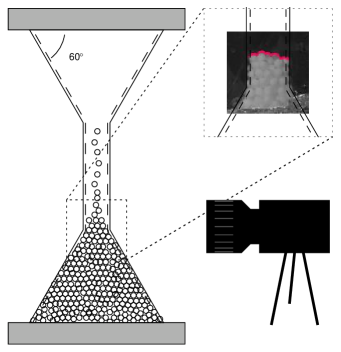
We prepared mechanically stable packings of monodisperse spheres immersed in fluids, in an hour-glass shaped apparatus (Fig. 1) placed on a vibration-isolation table. Using a variety of fluids (Table 1) and spheres (Table 2) we formed packings under a wide range of viscosity and buoyancy conditions allowing distinctions to be drawn between the relative merits of different parameters controlling approach to the RLP limit.
Packings were prepared by inverting the hour-glass shaped cell and allowing particles to settle through the fluid under gravity. The hour-glass geometry consists of two conical sections with a cone angle of and base diameter of 24 sphere-diameters () connected by a cylindrical neck of in diameter, which is only as wide as necessary to avoid jamming by arch formation in the neck. The narrow neck allows the passage of only a few particles at a time. (We have also deposited spheres singly by a mechanical dropper, with very similar results to those reported here.) The packing grows as a conical pile at the angle of repose (), which is much smaller than the cone angle of the container, thus eliminating any empty pockets near the walls. The conical cell was chosen to minimize the weight supported by the sloping walls of the container. No crystalline order was observed near the bottom or side walls.
Data for the volume fraction of the packing are taken when the top surface of the packing just enters the neck of the cell. The total volume of the packing is the volume of the cone plus the small contribution from the spheres that are in the neck. The latter is determined from an image of the topography of the top surface of the particles (inset Fig. 1). All volume fractions reported in this article are subject to the same systematic error in the range due to uncertainties in these volumes and in the volume of the hour glass.
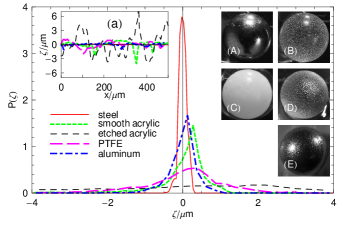
The particles used in our experiments are commercially available spheres of acrylic (PMMA), teflon (PTFE), steel, and aluminum with nominal diameter (see Table 2, Fig. 2). We also use acrylic spheres which were roughened by timed etches in acetone. All sets of spheres are very monodisperse and highly spherical with, at worst a deviation from sphericity of , a surface roughness of the same order, and a polydispersity of double this magnitude. These spheres are much larger than those used by Onoda and Liniger (, glass). The advantages of using large spheres are evident: attractive van der Waals forces are negligibly small compared to other forces in the problem and the particles are well characterized and of extremely high sphericity and monodispersity. Thus these experiments represent a better approximation to the idealized packing of hard, monodisperse spheres than previous experiments.
Apart from van der Waals attractionDong et al. (2006), experimental results on the low packing fraction limit are sensitive to other attractive forces of electrostatic and capillary origin. In setting up the apparatus, great care was taken to degas fluids and to introduce the fluid to the spheres slowly to avoid entraining air bubbles which form attractive bridges between between poorly wetted surfaces, especially rough ones. Pumping a vacuum on heated, stirred fluids for hours was often insufficient to avoid the appearance of attractive forces between spheres in non-wetting fluids, a phenomenon that has recently been associated with the existence of long-livedAttard et al. (2002); Borkent et al. (2007) nanobubbles capable of exerting forces comparable to gravity for PMMA spheres in our more closely density matched fluidsParker et al. (1994). To avoid this phenomenon, we have used well-wetting fluids when possible and avoided close density matches in poorly-wetting fluids so that the contribution of attractive forces is negligible. Where charging effects were suspected, we repeated measurements with salts added to screen coulomb interactions.
III Results and discussion
The problem of a sphere falling in the fluid involves five dimensionful parameters: and , the radius and density of the spheres; and , the density and dynamic viscosity of the fluid; and , the buoyancy-reduced gravitational acceleration in the fluid. Apart from (as suggested by Ref. Onoda and Liniger (1990)), other pertinent dimensionless groups are the Reynolds number and the Stokes number , where is the velocity of the particles as they approach the packing. In reducing our data we use for , the terminal velocity of the particle under Stokes drag, leading to the dimensionless parameters and . In the limit of gentle deposition, , . can be interpreted either as a dimensionless damping length, or as the ratio of kinetic energy to the potential energy, , which quantifies the degree to which a falling sphere can rearrange the packing.
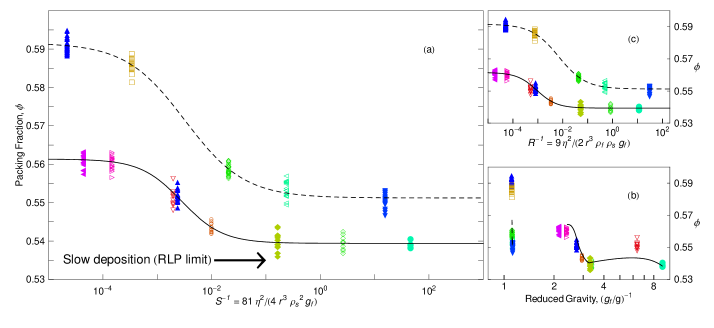
We display in Fig. 3 the major result of this paper. For spheres of a given material, the packing fraction decreases as sedimentation is done more gently. When plotted against the dimensionless group , the volume fraction approaches an asymptotic limiting low volume fraction which we may interpret as . We note the the limiting is different for spheres of different materials. The asymptotic limit is directly available from the data, and unlike in previous measurements need not be obtained by extrapolation (for which there is no reliable theoretical guideline). Each data point is taken with a different liquid, and not with a chemical series or a dilution series; the smooth approach to this limit thus suggests that the macroscopic parameters of the fluid and sphere are sufficient to fully characterize the preparation process, and that any microscopic interparticle interactions mediated by the fluid have been successfully suppressed.
Furthermore, Fig. 3(b) shows that the degree of density matching, quantified by , is not an appropriate parameter to define the RLP limit of this packing protocol. Low packing fractions can be achieved without density matching, by sedimenting in sufficiently viscous fluids. For a fluid of a given viscosity, RLP can of course be approached by varying , as the work of Onoda and Liniger suggests. The role of is however, not in reducing the static load on the packing structure, but purely in slowing down the dynamics of the packing process.
Fig. 3(c) shows that the volume fraction also smoothly approaches when plotted against the dimensionless group . However, unlike the plot of vs. , the asymptotic limit is attained at different values of for different materials, leading us to prefer as the best candidate for the relevant control parameter.
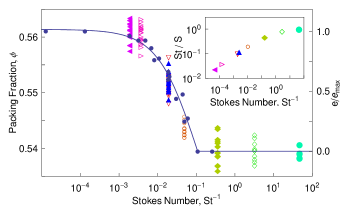
Additionally, previous measurements of collisions of fluid-immersed spheres on surfacesGondret et al. (2002) also show that the Stokes number – and not Reynolds number – is the relevant dimensionless parameter that defines the onset of bounce-free collisions. In addition to supporting the physical picture that the RLP limit corresponds to conditions where sequentially added spheres settle in the first mechanically stable location that they encounter, there is good quantitative agreement between the scale of where bouncing ceases, and where is attained. This correspondence is shown in Fig. 4. The Stokes number has also been identified as the parameter controlling the behavior of avalanches in fluid-immersed pilesCourrech du Pont et al. (2003).
We now return to the observation that the two curves in Fig. 3 corresponding to steel and acrylic spheres approach different values of of and respectively. With the mass density of the materials already accounted for, the only relevant differences are those of the contact mechanics of the spheres. In particular, the effective coefficient of static friction between spheres is different for these materials. Thus, unlike the RCP limit, the RLP limit is not a purely geometric problem, but involves the mechanics of interactions.
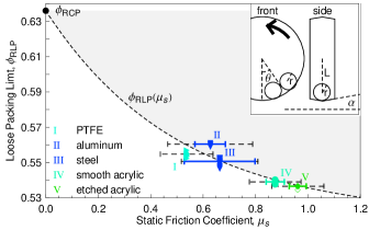
In order to more fully explore this observation, we have prepared packings of five different materials (Table 2) in the limit. The coefficient of static friction, is affected both by material as well as by surface topography; indeed we find that does not show a simple trend with surface roughness. To directly probe the material property of interest, we have devised a method to measure for sphere-on-sphere contacts between spheres immersed in a liquid. The schematic diagram inset in Fig. 5 shows the geometry of the setup: two spheres sit under gravity in the shallow v-groove of a track in the vertical plane. As the track rotates slowly, static friction between beads prevents them from rolling so they move with the track until they reach a maximal angle . At the tangential force between the spheres exceeds the maximum value allowed by the finite coefficient of static friction and the beads roll to a lower angle . can be then calculated from 333The rotation rate is set slow enough that viscous and centrifugal forces on the particles are negligible compared to gravity and friction. In this limit, where . In our setup, , and . is the distance from the center of the track to the centers of the spheres whereas the radius of the track at contact with the beads is .. In Fig. 5 we show decreases monotonically as the measured friction coefficient increases. The dependence on friction coefficient, , is consistent with as the coefficient of static friction, .
Our measurements of are made under conditions similar to those in our packing experiments, under the same small loads and fluid environments, and with sphere-on-sphere contacts that allow for both sliding and rolling. We are not aware of any other measurements of interparticle friction in this regime. The values of we observe are larger than those from our everyday experience at larger normal loads. Our data thus suggest a resolution of the puzzle that friction coefficients in simulated contact mechanics modelsZhang et al. (2001); Silbert et al. (2002); Song et al. (2008) were thought to be surprisingly large in order to achieve volume fractions as low as seen in experiments.
Finally, we turn from the limit to the large Stokes regime. Surprisingly, we see a plateau in the value of , well separated from the low Stokes limit. The plateau does not scale simply with friction coefficient , and presumably also involves other particle properties such as inelasticity. We speculate that this plateau value may be related to the “critical state” of soil mechanics. The transition from this plateau to is clearly of interest, but is not easily explored by merely tuning with fluid parameters.
IV Conclusion
The strengths of our experiments are (i) the extremely well-controlled sphericity and monodispersity of the particles, (ii) detailed characterizations of relevant particles properties such as surface roughness and of friction coefficient under deposition conditions, (iii), broad coverage of fluid parameters, and (iv) employing large enough particles to be well outside the influence of any attractive interactions. Thus our experiments provide the best available approximation to the idealized problem of the packing of monodisperse frictional spheres. Despite our choice of experimental geometry, the relatively small system size in our experiments may introduce wall-effects. It is clear, however, that the values of obtained by the sequential deposition in our experiment are comparable with those obtained by collective packing schemesOnoda and Liniger (1990); Jerkins et al. (2008), and therefore our findings should also be applicable to those packing protocols.
Previous experiments have shown that looser packings may be prepared if sedimentation is done more gently. Our results strengthen this intuitive expectation in three significant directions. The first is that we arrive at a sharp definition of “gentle” deposition: this limit is governed by the Stokes number, . The second conclusion is that the RLP limit is achieved at a nonzero threshold value of , below which particles entering the packing do not have the ability to explore the landscape of deposited particles, or to rearrange it. Finally, since we eliminate the effect of attractive forces by packing at finite values of , we establish the existence of a for cohesionless spheres.
We also provide the first direct experimental study of the friction-dependence of by measuring the friction coefficients between particles at small normal loads. Friction stabilizes packings at volume fractions considerably below . The evolution of a packing from the RLP boundary to the RCP boundary, and the structure and mechanical properties of the intermediate states remain largely unexplored.
V Acknowledgments
We acknowledge funding from the NSF through NSF-DMR 0606216 and 0907245, and the use of facilities funded by NSF-MRSEC 0820506. We thank C. S. O’Hern for valuable conversations.
References
- Scott (1960) G. D. Scott, Nature, 1960, 188, 908–909.
- Macrae and Gray (1961) J. C. Macrae and W. A. Gray, Br. J. Appl. Phys, 1961, 12, 164–172.
- Rutgers (1962) R. Rutgers, Nature, 1962, 193, 465–466.
- Scott and Kilgour (1969) G. D. Scott and D. M. Kilgour, J. Phys. D: Appl. Phys., 1969, 2, 863–866.
- Chaudhuri et al. (2010) P. Chaudhuri, L. Berthier, and S. Sastry, PRL, 2010, in press.
- Jalali and Li (2004) P. Jalali and M. Li, J. Chem. Phys., 2004, 120, 1138–1139.
- Torquato et al. (2000) S. Torquato, T. M. Truskett and P. G. Debenedetti, Phys. Rev. Lett., 2000, 84, 2064–2067.
- Gao et al. (2006) G.-J. Gao, J. Bławzdziewicz and C. S. O’Hern, Phys. Rev. E, 2006, 74, 061304.
- Kamien and Liu (2007) R. D. Kamien and A. J. Liu, Phys. Rev. Lett., 2007, 99, 155501.
- Bernal (1964) J. D. Bernal, Proc. R. Soc. A, 1964, 280, 299–322.
- Onoda and Liniger (1990) G. Y. Onoda and E. G. Liniger, Phys. Rev. Lett., 1990, 64, 2727–2730.
- Dong et al. (2006) K. J. Dong, R. Y. Yang, R. P. Zou and A. B. Yu, Phys. Rev. Lett., 2006, 96, 145505.
- Weitz and Oliveria (1984) D. A. Weitz and M. Oliveria, PRL, 1984, 52, 1433–1436.
- O’Hern et al. (2002) C. S. O’Hern, S. A. Langer, A. J. Liu and S. R. Nagel, Phys. Rev. Lett., 2002, 88, 075507.
- Jerkins et al. (2008) M. Jerkins, M. Schröter, H. L. Swinney, T. J. Senden, M. Saadatfar and T. Aste, Phys. Rev. Lett., 2008, 101, 018301.
- Zhang et al. (2001) Z. P. Zhang, L. F. Liu, Y. D. Yuan and A. B. Yu, Powder Technol., 2001, 116, 23 – 32.
- Silbert et al. (2002) L. E. Silbert, D. Ertaş, G. S. Grest, T. C. Halsey and D. Levine, Phys. Rev. E, 2002, 65, 031304.
- Song et al. (2008) C. Song, P. Wang and H. A. Makse, Nature, 2008, 453, 629–632.
- Ciamarra and Coniglio (2008) M. P. Ciamarra and A. Coniglio, Phys. Rev. Lett., 2008, 101, 128001.
- Lide (1999) CRC Handbook of chemistry and physics, ed. D. R. Lide, CRC Press, Boca Raton, 80th edn., 1999.
- Attard et al. (2002) P. Attard, M. P. Moody and J. W. G. Tyrrell, Physica A (Amsterdam), 2002, 314, 696 – 705.
- Borkent et al. (2007) B. M. Borkent, S. M. Dammer, H. Schönherr, G. J. Vancso and D. Lohse, Phys. Rev. Lett., 2007, 98, 204502.
- Parker et al. (1994) J. Parker, P. Claesson and P. Attard, J. Phys. Chem., 1994, 98, 8468–8480.
- Gondret et al. (2002) P. Gondret, M. Lance and L. Petit, Phys. Fluids, 2002, 14, 643–652.
- Majumder and Barnwal (2004) A. K. Majumder and J. P. Barnwal, IE (I) Journal-M, 2004, 85, 17–19.
- Courrech du Pont et al. (2003) S. Courrech du Pont, P. Gondret, B. Perrin and M. Rabaud, Phys. Rev. Lett., 2003, 90, 044301.