Estimating Terminal Velocity of Rough Cracks
in the Framework of Discrete Fractal Fracture Mechanics
Abstract
In this paper we first obtain the order of stress singularity for a dynamically propagating self-affine fractal crack. We then show that there is always an upper bound to roughness, i.e. a propagating fractal crack reaches a terminal roughness. We then study the phenomenon of reaching a terminal velocity. Assuming that propagation of a fractal crack is discrete, we predict its terminal velocity using an asymptotic energy balance argument. In particular, we show that the limiting crack speed is a material-dependent fraction of the corresponding Rayleigh wave speed.
- Keywords:
-
Dynamic fracture, Fractal crack, Order of stress singularity, terminal velocity.
1 Introduction
A theoretical framework for including inertial effects during a rapid crack growth was first proposed by Mott [1948], who adopted the analysis of Griffith [1921] as a starting point. The idea is based on a simple addition of a kinetic energy term to the expression for the total energy of the cracked system. According to Mott’s extension of Griffith’s criterion, the requirement that the system remains in thermodynamic equilibrium with its surroundings as the crack extends leads to the following expression in terms of the well-known fracture parameters: , where is energy release rate, is specific surface energy, is kinetic energy density, and “a” is the characteristic length of the crack. Mott defined a domain R that receives stress-wave “messages” from the crack tip and then argued that the total kinetic energy can be written as . While Mott’s analysis lacks rigour, it is instructive in the way it highlights some of the important features of a running crack without excessive mathematical complication.
The first important contribution to the problem of a moving crack with constant velocity was the work of Yoffe [1951]. The Yoffe problem consists of a mode I crack of fixed length traveling through an elastic body at a constant speed under the action of uniform remote tensile loading. Yoffe [1951] obtained the stress distribution near the tip of a rapidly propagating crack in a plate of isotropic elastic medium. The result was that the stresses depend on the crack tip velocity and reduce to the solution of Inglis [1913] when the velocity is zero.
Roberts and Wells [1954] used Mott’s extension of Griffith’s criterion to predict the limiting velocity of the crack extension. By taking the boundary of the region to be a circle of radius centered at the crack tip, they estimated , where is the longitudinal sound wave speed. They defined this cutoff region as the border of the disturbed zone by the stress waves emanated from the crack tip. Using this assumption and taking a stress field similar to that of the static case they roughly estimated the limiting crack velocity to be about when . Steverding and Lehnigk [1970] studied the problem of the response of cracks to stress pulses and found an equation of motion for such cracks. They also obtained the limiting velocity of crack extension caused by stress pulses by using asymptotic solutions to be about , where is the Rayleigh wave speed. There have also been some other efforts on finding the equation of motion for dynamically propagating cracks. Berry [1960a, b] was the first to find an equation of motion for dynamic propagation of cracks. He found out that the details of the motion of a crack are determined by the state of stress at the point of fracture, and that the observed critical stress is (infinitesimally) greater than that given by the Griffith’s criterion and is probably determined by the size of the defect in the sample and the rate of straining. He also obtained solutions for the equation of motion for fracture in tension and fracture in cleavage in both constant force and constant velocity cases. See Bouchbinder, et al. [2010] for a recent review of dynamic fracture mechanics.
The inadequacy of the classical fracture mechanics theories in problems such as predicting infinite strength for elastic bodies without any cracks, for example, was the motivation for some researchers to propose new failure theories. Novozhilov [1969] introduced a non-local stress criterion and gave the condition of the brittle crack propagation in mode I as , where is spatial averaging over the interval , is the complete (not only asymptotic) stress field around the crack tip , is the ideal strength of the material, and is the minimum admissible crack advance named by him a fracture quantum. According to Novozhilov this criterion can be used only with the complete expression of the stress-field, and not with its asymptotic form. However, the complete expression is rarely known. Another restriction in Novozhilov’s approach was that the size of fracture quantum assumed to be the atomic spacing. Pugno and Ruoff [2004] introduced their so-called quantized fracture mechanics (QFM) approach, which modified Novozhilov’s theory. In QFM, the restrictions of Novozhilov’s theory were removed and this made QFM a useful approach for analysis of very short cracks (see also Krasovs’kyi [2006]; Morozov and Petrov [2002]; Cornetti, et al. [2006]; Leguillon [2002] for more related works). In their approach the differentials in Griffith’s criterion were replaced by finite differences (see Wnuk and Yavari [2008] for a discussion). For vanishing crack length, QFM predicts a finite ideal strength in agreement with the prediction of Orowan [1955].
In most models in fracture mechanics cracks are assumed to be smooth for mathematical convenience. However, in reality fracture surfaces are rough and “roughness” evolves in the process of crack propagation. Fracture surfaces of many materials of interest are fractals, a fact that has been experimentally established by many researchers. A fractal dimension (roughness exponent) is not enough to uniquely specify a fractal set and this is why all one can hope for achieving having only a fractal dimension (roughness exponent) is a qualitative analysis. Effects of fractality on fracture characteristics of rough cracks have been investigated by several groups in the past two decades (see Mosolov [1991]; Gol’dshteǐn and Mosolov [1991, 1992]; Balankin [1997]; Borodich [1997]; Carpinteri [1994], Cherepanov, et al. [1995]; Xie [1989, 1995]; Yavari, et al. [2000]; Yavari [2002]; Yavari, et al. [2002a, b]; Wnuk and Yavari [2003, 2005, 2008, 2009], and references therein). Here our interest is to estimate the observed terminal velocity of a rough crack propagating dynamically in an elastic medium.
Wnuk and Yavari [2008] extended quantized (finite) fracture mechanics ideas for fractal cracks. They presented a modification of the classical theory of brittle fracture of solids by relating discrete nature of crack propagation to the fractal geometry of the crack. Their work is based on the idea of using an equivalent smooth blunt crack with a finite radius of curvature at its tips for a given fractal crack [Wnuk and Yavari, 2003, 2005]. By taking the radius of curvature of the equivalent blunt crack as a material property, they showed that fractal dimension of the crack trajectory is a monotonically increasing function of the nominal crack length. This result was an analytical demonstration of the mirror-mist-hackle phenomenon for rough cracks. Later they showed that assuming a cohesive zone ahead of a fractal crack, the size of the cohesive zone increases while the crack propagates [Wnuk and Yavari, 2009].
To our best knowledge, the only contributions related to the dynamic fracture of fractal cracks are Xie [1995] and Alves [2005]. Xie [1995] introduced a fractal kinking model of the crack extension path to describe irregular crack growth. Then by using the formula proposed by Freund [1998] for calculating dynamic stress intensity factor for arbitrary crack tip motion he calculated the stress intensity factor for the assumed fractal crack path. He concluded that the reason for having terminal velocities lower than the Rayleigh wave speed is the fractality of the crack path. Alves [2005] used a fractal model for rough crack surfaces in brittle materials. He tried to explain the effect of fractality of fracture surfaces on the stable (quasi-static) and unstable (dynamic) fracture resistance. He concluded that fractal dimension has a strong influence on the rising of the R-curve in brittle materials. He also argued that the reason for having terminal velocities lower than Rayleigh wave speed is the roughness of the fracture surfaces that makes the nominal (projected) and local crack tip velocities different.
Dulaney and Brace [1960] modified Mott’s analysis of energy balance and showed that for a crack of initial and current lengths and , respectively, compared to the similar equation obtained by Mott. Here is the terminal velocity and is proportional to . They also carried out tests of terminal velocity on PMMA specimens and showed that the measured velocity differs only about ten percent from the predicted value by Roberts and Wells [1954]. Recently, Chekunaev and Kaplan [2008, 2009] studied the terminal velocity by replacing a mode I crack under pressure on its faces by considering cohesive forces and replacing the crack by an equivalent distribution of dislocations. They obtained simple expressions for the potential and kinetic energies of the environment of the moving crack. They also obtained an expression for an equivalent mass for the crack tip, i.e. a point mass that has the same kinetic energy as the whole cracked system. Their equivalent mass depends on a truncation radius in the form of , where is the half crack length. For a uniform external pressure they showed that the crack tip speed can be expressed as , where depends on both mechanical properties and . Their terminal velocity has the form that they approximate by , for functions and that are given in [Chekunaev and Kaplan, 2008, 2009]. It should be mentioned that their equivalent mass is positive for all and . Note that their equivalent mass is independent of the crack tip speed and hence kinetic energy is an increasing function of crack tip velocity.
This paper is organized as follows. In §2 an asymptotic method will be used to determine the order of stress singularity for a dynamically propagating fractal crack. In §3 dynamic propagation of a fractal crack is investigated. We first show that in the intermediate crack growth regime, i.e. after the initial phase of crack growth, roughness change is so small that a terminal roughness exponent can be assumed. The phenomenon of reaching a limiting speed is predicted using some simplifying assumptions. The predicted limiting crack speeds for different brittle amorphous materials are shown to have good agreement with the experimental results. Finally, conclusions are given in §4.
2 Order of stress singularity for a dynamically propagating fractal crack
Consider a crack, whose tips are growing in opposite directions with equal velocities.111To avoid problems with stress wave reflections we can assume that the crack is semi-infinite. This assumption will not change anything in the following analysis. The crack unloads some area of the body, and while propagating, size of the unloaded area will increase. The form of the stress field in the close vicinity of the crack tip is of interest as almost all fracture energy will be consumed through different processes in this zone. In the following, the asymptotic behavior of some important parameters that contribute to energy balance will be investigated. Here, we assume that the singularity of stress is of the form , where is distance from the crack tip. In the sequel we find an expression for the order of stress singularity .
Several experimental observations confirm that energy consuming phenomena such as temperature rise, acoustic and phonon emissions, etc. occur in the close vicinity of the moving crack tip. There is one common aspect in all these phenomena; they all have a kinetic origin. To be more precise they are all results of fast movements or oscillations of the particles around the moving crack tip. This means that the velocity of the particles around the crack tip is of great importance. The particle velocity at a point depends on two main parameters: the crack tip speed and the strain at the point [Freund, 1998]. Asymptotic behavior of particle velocity in the close vicinity of a smooth moving crack tip is similar to that of stress for all modes of fracture. For the classic case we have . The classic case is a limiting case of fractal model, which is when the roughness (Hurst) exponent () of a self-affine crack trajectory is equal to unity. In the case of a fractal crack, we know that and hence dimensional analysis tells us that
| (2.1) |
where is a dimensionless function and is short for .
Asymptotic behavior of the true length of the crack trajectory is also important. The first experimental study on fractal characteristics of fracture surfaces was carried out by Mandelbrot, et al. [1984] who showed that the fracture surfaces of steel are fractals. Since then many experimental investigations have been done. For example, the investigations on the concrete fracture surfaces by Saouma, et al. [1990] and Saouma and Barton [1994] showed that the fracture surfaces of concrete are also fractals. Based on the experimental observations, we assume that fracture surfaces are self-affine fractals. The asymptotic behavior of the true crack length growth is [Mandelbrot, 1985, 1986a, 1986b; Yavari, et al., 2002a]
| (2.2) |
where is some characteristic crack growth length.222There are different definitions of fractal dimension, e.g. box dimension (), compass dimension (), and mass dimension (). In the case of a self-similar fractal, all of these dimensions have the same value, but this is not the case for self-affine fractal sets. The local values of the box dimension (using small boxes) and mass dimension (using small radii) are both . The compass dimension has a local value . For more details see [Mandelbrot, 1985, 1986a, 1986b]..
The changes of kinetic and strain energies of the body when the crack length growth is are (summation over repeated indices is implied):
| (2.3) |
where is the area element. If it is assumed that the change of the strain and kinetic energies is dominant in a small neighborhood around the crack tip, in the above relations can be replaced by . Kinetic and strain energy changes have the following asymptotic expressions:
| (2.4) |
In addition to the kinetic and strain energies, there is another important energy term, namely the surface energy. By assuming a constant specific surface energy per unit of a fractal measure, the surface energy that is required for the formation of a self-affine fractal crack has the following asymptotic behavior333For every short cracks surface energy is length dependent [Ippolito, et al., 2006]. However, we are interested in obtaining the limiting crack velocity that corresponds to crack lengths much larger than any fracture quantuum and hence specific surface energy is a material constant.:
| (2.5) |
For quasi-static crack growth, Griffith’s criterion can be written as , while for dynamics crack growth it is written as , where is the change of the strain energy in the body due to crack growth, is the required energy for the formation of the new fracture surfaces, and is the change of kinetic energy in the body. Using the equality of asymptotic expressions of energy terms the order of stress singularity can be obtained as
| (2.6) |
Thus
| (2.7) |
which is identical to that of a stationary crack [Mosolov, 1991; Gol’dshteǐn and Mosolov, 1991, 1992; Balankin, 1997; Yavari, et al., 2000, 2002a; Yavari, 2002]. Therefore, the stress field has the following asymptotic form:
| (2.8) |
3 Terminal velocity of rough crack growth in brittle materials
From many studies of fracture surfaces formed in brittle materials, it is believed that the surfaces created by the process of dynamic fracture have a characteristic structure, referred to as mirror–mist–hackle in the literature. This structure has been observed to occur in materials as diverse as glass and ceramics, noncrosslinked glassy polymers such as PMMA and crosslinked glassy polymers such as Homalite 100, polystyrene and epoxies (for more details see Lawn [1993]; Gao [1993]; Hauch and Marder [1998]; Ravi-Chandar [1998]; Fineberg and Marder [1999] and references therein).
The prediction and measurement of the crack tip speed has received great attention from researchers in the field of dynamic fracture. As was mentioned earlier, Roberts and Wells [1954] were the first to find a theoretical prediction for limiting crack tip velocity. Their calculations based on the Mott’s extension of Griffith’s criterion predicted crack tip speed of (for ), where . Steverding and Lehnigk [1970] also predicted the terminal velocity by using an asymptotic solution and found it to be about . Many researchers argue that the maximum velocity attainable by any moving surface of discontinuity should be identified with the velocity of the Rayleigh surface waves . Ravi-Chandar [1998] reached the following three major conclusions about the crack speed measurements: i) There is an upper limit to the speed with which dynamic cracks propagate. ii) This limiting crack speed is significantly lower than the Rayleigh surface wave speed of the material. iii) The limiting speed is not a fixed fraction of the Rayleigh wave speed; this fraction is material dependent. The data gathered by Fineberg and Marder [1999] indicates that in amorphous materials such as PMMA and glass, the maximum observed velocity of crack propagation barely exceeds about of the predicted value.444Note that this is true only for isotropic materials. In an anisotropic body, terminal velocity can reach up to ninety percent of the Rayleigh wave speed. See the review by Fineberg and Marder [1999] for more details. Here we restrict ourselves to crack propagation in an isotropic medium. In the following we predict the terminal crack tip velocity using an asymptotic energy balance argument.
To illustrate the process of reaching a constant crack tip speed, suppose that an infinite domain with an initially smooth crack is subjected to remote tensile stresses . The crack unloads some area of the body that can be approximated by a disk of radius [Yavari, et al., 2002a]. To specify this circle we need to define a characteristic length for the problem. There is experimental evidence that the dynamic fracture processes approach a steady state and thus taking the crack length as a characteristic length will contradict a steady state condition.555In the case of a semi-infinite crack there is no characteristic length. Therefore, we seek a new characteristic length in the problem. Here the fracture quantum is taken as the material characteristic length. Therefore, for a fractal crack the radius of the disk is assumed to be proportional to , i.e. from dimensional analysis arguments. More precisely, for a self-affine crack, the following relation holds for the radius of the dominance region of strain energy release:
| (3.1) |
where is a dimensionless function. We assume that the crack is initially smooth (). At time the strain energy density reaches a critical value and suddenly the crack starts to grow. As the nominal length of the crack increases, the roughness of the fracture surfaces increases as well ( decreases) due to the mirror-mist-hackle transition phenomenon. We postulate that crack surfaces reach a terminal roughness. It should be noted that a self-affine fractal model for is a plane-filling set and hence the limiting roughness lies in the range . Let us justify our postulate of reaching a terminal velocity using a crack branching argument. The required surface energy for the formation of a self-affine fractal crack has the asymptotic behavior . To estimate the actual growth of a self-affine fractal crack, suppose that the nominal crack growth step is equal to , where is fracture quantum and . According to fractal geometry concepts the actual growth length of a self-affine fractal crack with the nominal growth step size of has the asymptotic form . Therefore, the required surface energy has the asymptotic behavior of the form . Now we argue that for some values of the required surface energy for the formation of two new surfaces (assuming that these new cracks are initially smooth) will become smaller than the required surface energy for the continuation of the single (roughened) crack.666Eshelby [1971] suggested that a crack would branch when the energy going into the creation of a single propagating crack is enough to support two single cracks. For more details see Fineberg and Marder [1999]. For roughness exponents smaller than this limiting roughness (denoted by ) one can write:
| (3.2) |
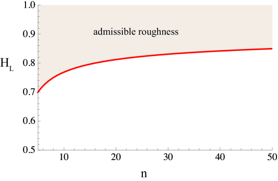
Therefore, it is probable that by reaching the increase of energy flow toward the crack tip causes branching of the crack. This roughness limit can be estimated by solving for different values of .777Note that the equation that we need to solve is for a function such that . As we do not have an explicit form for , we assume it is approximately equal to unity. If we assume other constant values for the only change will be value of the approximate terminal roughness. It seems that the choice leads to a reasonable terminal roughness in agreement with experiments. We should also emphasize that the exact value of this terminal roughness will not change any of the subsequent results. The results are presented in Fig. 3.1. Note that for each the acceptable values of for having a single crack are . There are different arguments in the literature for explaining the branching phenomena in fracture but many of them are not in agreement with the experimental results.888Once a crack bifurcates, single crack models are, of course, no longer valid. Therefore, a theory describing a single crack can, at best, provide a criterion for when crack branching occurs. A number of such criteria for the onset of crack branching have been proposed. The criterion due to Yoffe [1951] and extremal energy density criteria [Sih, 1973; Theocaris and Georgiadis, 1985; Ramulu and Kobayashi, 1986; Adda-Bedia and Amar, 1996] all suffer from the common problem that the velocities predicted for the onset of branching are much higher than the observed velocities in the experiments. Additional criteria such as postulating a critical value of the stress intensity factor, have not been consistent with experiments [Ramulu and Kobayashi, 1985; Arakawa and Takahashi, 1991] since measurements at the point of branching show considerable variation of the stress intensity factor . Note that in the range , is almost constant. For large , increases but very slowly. Note that as , [Bleistein and Handelsman, 1986]. This means that increases indefinitely but very slowly as increases. Note also that for short cracks surface energy depends on and hence in Fig. 3.1, is not shown.
Since the pioneering work of Mandelbrot, et al. [1984] understanding the morphology of fracture surfaces has been a very active field of research. Much recent effort has been focused on characterizing fracture surfaces in terms of a roughness exponent. There are many researchers who argue that there exists a universal roughness for fracture surfaces. Their studies on the fracture surfaces of different materials indicate that for both quasi-static and dynamic fracture a universal roughness exponent of approximate value 0.8 can be obtained for values of (scale of observation) greater than a material-dependent scale, [Bouchaud, et al., 1990; Bouchaud, 1997, 2003; Måløy, et al., 1992; Daguier, et al., 1996, 1997; Ponson, et. al, 2006]. What we see from our simple crack branching argument is in agreement with these experimental studies.
By taking the nominal crack growth step to be the actual crack growth length for a self-affine crack propagation can be estimated as follows:
| (3.3) |
Note that we assume that the crack lies in the plane with nominal growth in the direction. Let us define the nominal crack-tip velocity by and the actual velocity by , where is the required time for growth of the fractal crack by the nominal amount of . Therefore, the following relation holds between nominal and actual velocities of the crack tip:
| (3.4) |
When the crack roughness reaches its limiting value , and hence . Now if the limit of is , we see that limit of is about from this rough estimate. Gao [1993] used a wavy-crack model and observed that depending on roughness local crack tip velocity can be as large as twice the apparent crack tip speed. He also observed that when apparent crack speed is dynamic energy release rate is maximized.
Reaching the terminal roughness exponent has another important consequence; after reaching the radius of the dominance zone of strain energy release will remain unchanged, i.e. reaches a constant value. Now we are back to the main problem of having a terminal velocity for crack propagation in brittle materials. As we concluded earlier from the experimental observations, almost all the released strain energy will be converted into kinetic energy. Therefore, we are concerned with the changes of strain and kinetic energies, i.e. and . The dominant change of strain energy can be written as follows:
| (3.5) |
Similar to the case of dynamic fracture of a smooth crack, for a fractal crack the following stress and strain fields at the moving crack tip are assumed:
| (3.6) |
Substituting the above asymptotic fields into Eq.(3.5), we obtain:
| (3.7) |
In the case of a mode I smooth crack, stress field explicitly depends on the instantaneous crack tip speed [Freund, 1998]. An immediate consequence of this is that the near tip field for the time-dependent motion is identical to that for steady state crack growth in the same material up to a time-dependent proportionality constant. This was demonstrated by Freund and Clifton [1974], Nilsson [1974], and Achenbach and Bažant [1975], each of whom compared asymptotic solutions for nonuniform crack growth with earlier results based on the assumption of steady growth obtained by Cotterell [1964], Rice [1968], and Sih [1970].
Freund [1972a, b] suggested an indirect method for determining the dynamic stress intensity factor for mode I crack propagation with nonuniform crack growth and a general loading condition. The result was that the dynamic stress intensity factor for arbitrary motion of the crack tip is proportional to the corresponding quasi-static stress intensity factor with a universal proportionality constant, i.e. , where is the instantaneous crack characteristic length, and
| (3.8) |
where , and are the Rayleigh wave speed, dilatational wave speed, and the crack tip velocity, respectively, and is close to unity. Therefore, can be approximated by
| (3.9) |
where .999Note that for plane strain , and for plane stress . We assume that the above result holds for a fractal crack, i.e.101010Xie [1995] made a similar assumption for each prefractal crack trajectory in his fractal model.
| (3.10) |
The quasi-static stress intensity factor for a fractal crack of projected length subjected to uniform far-field stress is [Yavari, 2002; Wnuk and Yavari, 2003]. Thus, for very long cracks (intermediate crack growth regime) the rate of change of stress intensity factor becomes vanishingly small, i.e.
| (3.11) |
Now, we can use the above arguments in the calculation of the strain energy release. If roughness reaches its terminal value , the size of the dominance zone of strain energy release will became approximately constant and as a result the order of stress singularity will remain unchanged. In addition to this, increasing the nominal crack length to large values the change in the stress intensity factor becomes vanishingly small. In other words, the stress intensity factor becomes approximately constant. Under these conditions, strain energy will change only due to the change of the nominal velocity of the crack tip. Strain energy in the disk is :
| (3.12) |
where for short. It can be shown that the effect of infinitesimal changes of crack tip velocity on the angular variation of the stress field is negligible and hence, the change of strain energy in the disk due to the change of crack tip velocity can be simplified to read111111Note that denotes change in the quantity due to crack growth (change in the crack length) while denotes change in the quantity due to change in the crack speed.
| (3.13) |
where
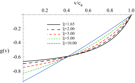
| (3.14) |
Fig. 3.2 schematically shows the behavior of the function . Note that the above integral is positive and hence strain energy change is always negative; for all values of and strain energy is released as expected.
Now, we assume that the change of kinetic energy due to the released strain energy is dominant in a disk with radius . Similar to the case of determining radius of dominance zone of strain energy release, the fracture quantum () is the characteristic length in the problem. Assuming that , dimensional analysis tells us that:
| (3.15) |
where is Rayleigh wave speed, and is a dimensionless function. Now we have the following relation for the amount of kinetic energy change in the disk :
| (3.16) |
where is the velocity components of material particles. At the radial distance from the crack tip, the particle velocity depends on the crack tip velocity and the strain at the particle position. The velocity of particles in the dominance zone of kinetic energy, , is also a function of the angular position of particles and the ratio of the crack tip speed and a characteristic wave speed. If we assume that for the limiting roughness the effect of the change of the nominal crack tip speed on the size of the dominance zone is negligible, the dominance zone of the kinetic energy change is fixed, and once again these conditions dictate that kinetic energy can be written as:
| (3.17) |
where is short for . We know that the effect of infinitesimal changes of crack tip velocity on the angular variation of the particle velocity field is negligible, and hence the change of kinetic energy due to the change of crack tip velocity can be written as
| (3.18) | |||||
where
| (3.19) |
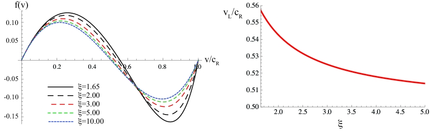
Fig. 3.3(a) schematically shows the function for different values of . Note that in plane strain , and for plane stress and hence the appropriate range of should be considered for each case.
The schematic graph of the function in Fig. 3.3(a) shows an interesting phenomenon: After reaching some value of crack tip speed increasing the change of kinetic energy becomes negative. Because the particle velocity inside the dominance zone of kinetic energy is proportional to the crack tip speed increasing the crack tip speed the kinetic energy change must be positive, and therefore the crack can not pass this limiting speed . In other words, when the crack tip speed increases the kinetic energy of the region around the crack tip must increase as well, i.e. kinetic energy must be an increasing function of the crack tip speed. In terms of the equivalent crack tip mass introduced by Chekunaev and Kaplan [2008, 2009], our argument is equivalent to saying that the equivalent mass must always be positive (note that their equivalent mass is independent of velocity), which is the case as was mentioned in §1.
The predicted limiting speed for Glass, Homalite-100, PMMA, K5 (Glass), K6 (Glass), and SF6 (Glass) are as follows:
-
i)
Glass (): ,
-
ii)
Homalite-100 (): ,
-
iii)
PMMA (): ,
-
iv)
K5 (Glass) (): ,
-
v)
K6 (Glass) (): ,
-
vi)
SF6 (Glass) (): ,
where and .
| Material | Author | ||
|---|---|---|---|
| Glass | Schardin and Struth [1938] | 0.30 | 0.52 |
| Edgerton and Bartow [1941] | 0.28 | 0.47 | |
| Bowden, et al. [1967] | 0.29 | 0.51 | |
| Anthony et al. [1970] | 0.39 | 0.66 | |
| PMMA | Dulaney and Brace [1960] | 0.36 | 0.62 |
| Cotterell [1965] | 0.33 | 0.58 | |
| Paxson and Lucas [1973] | 0.36 | 0.62 | |
| Fineberg et al. [1992] | 0.58-0.62 | ||
| Homalite-100 | Beebe [1966] | 0.19 | 0.33 |
| Kobayashi and Mall [1978] | 0.22 | 0.37 | |
| Dally [1979] | 0.24 | 0.38 | |
| Ravi-Chandar and Knauss [1984a, b, c, d] | 0.45 | ||
| Hauch and Marder [1998] | 0.37 | ||
| K5 (Glass) | Senf, et al. [1994] | 0.29-0.3 | 0.5-0.52 |
| K6 (Glass) | Senf, et al. [1994] | 0.27-0.3 | 0.47-0.51 |
| SF6 (Glass) | Senf, et al. [1994] | 0.2-0.23 | 0.34-0.4 |
It is seen from Table 1. that there is some scatter in the experimental data and this makes any comparison with experimental data difficult. However, we see that our estimates are close to the experimental data. It should be noted that what we have obtained for terminal velocity is an upper bound.121212Note that any velocity larger than our calculated leads to a decreasing kinetic energy change that is not physical. However, this does not mean that a lower terminal velocity is not possible. In other words, what we calculate is an upper bound to terminal velocity. Interestingly, all the experimentally measured velocities (except PMMA) are smaller than our prediction of the terminal velocity.
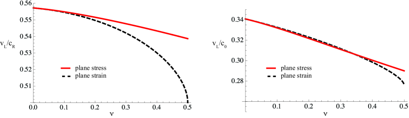
The relations between various wave speeds and are: (plane strain dilatational wave speed), (plane stress dilatational wave speed), (shear wave speed), (Rayleigh wave speed), where for plane strain and for plane stress. In Fig. 3.4 the normalized limiting velocities and are plotted for different values of Poisson’s ratio and for both cases of plane stress and plane strain. The calculations show that depending on the Poisson’s ratio the limiting velocities are in the range for plane strain and in the range for plane stress.
4 Conclusions
In this paper, we first obtained the asymptotic stress field around the tip of a dynamically propagating self-affine fractal crack. We then showed that there is always a lower bound to roughness exponent. We next looked at crack propagation and the asymptotic behaviors of kinetic and strain energy changes due to crack growth. We obtained an upper bound for terminal velocity by postulating that the kinetic energy change must be a monotonically increasing function of nominal crack tip speed. We predicted a material-dependent terminal velocity in the range and for plane stress and plane strain, respectively. We should emphasize that our asymptotic analysis only gives an estimate of terminal velocity. It was observed that for several amorphous brittle materials our predicted terminal velocities are in good agreement with the experimental data. In summary, our main results are: i) Fractal cracks tend to reach an approximately constant terminal roughness close to . ii) There is a terminal velocity of crack propagation lower than the Rayleigh wave speed. iii) The terminal velocity is a material-dependent fraction of the corresponding Rayleigh wave speed. iv) This material-dependent fraction only depends on the Poisson’s ratio.
References
- Achenbach and Bažant [1975] Achenbach J.D., Bažant Z.P., Elastodynamic near-tip stress and displacement fields for rapidly propagating cracks in orthotropic media, Journal of Applied Mechanics 42(1975):183-9.
- Adda-Bedia and Amar [1996] Adda-Bedia M., Amar M.B., Stability of quasiequillibrium cracks under uniaxial loading, Physics Review Letters 76(1996):1497-500.
- Alves [2005] Alves L.M., Fractal geometry concerned with stable and dynamic fracture mechanics, Theoretical and Appiled Fracture Mechanics 44(2005):44-57.
- Anthony et al. [1970] Anthony S.R., Chubb J.P., Congleton J., The crack branching velocity, Philosophical Magazine 22(1970):1201-61.
- Arakawa and Takahashi [1991] Arakawa K., Takahashi K., Branching of a fast crack in polymers, International Journal of Fracture 48(1991):245-54.
- Balankin [1997] Balankin A.S., Physics of fracture and mechanics of self-affine cracks, Enigineering Fracture Mechanics 57(1997):135-207.
- Beebe [1966] Beebe W.M., An experimental investigation of dynamic crack propagation in plastic and metals, Ph.D Thesis, California Institute of Technology, Pasadena, CA, (1966).
- Berry [1960a] Berry J.P., Some kinetic considerations of the Griffith criterion for fracture I: Equations of motion at constant force, Journal of Mechanics and Physics of Solids8(1960):194-206.
- Berry [1960b] Berry J.P., Some kinetic considerations of the Griffith criterion for fracture II: Equations of motion at constant deformation, Journal of Mechanics and Physics of Solids8(1960):207-216.
- Bleistein and Handelsman [1986] Bleistein N. and Handelsman R.A., Asymptotic Expansions of Integrals, Dover, New York(1998).
- Borodich [1997] Borodich F.M., Some fractal models of fracture, Journal of the Mechanics and Physics of Solids 45(2)(1997):239-59.
- Bouchaud, et al. [1990] Bouchaud E., Lapasset G., Planès J., Fractal dimension of fractured surfaces: a universal value?, Europhysics Letters 13(1990):73-79.
- Bouchaud [1997] Bouchaud E., Scaling properties of cracks, Journal of Physics: Condensed Matter 9(1997):4319.
- Bouchaud [2003] Bouchaud E., The morphology of fracture surfaces: a tool for understanding crack propagation in complex materials, Surface Review and Letters 10(5)(2003):797-814.
- Bouchbinder, et al. [2010] Bouchbinder E., Fineberg, J., Marder, M., Dynamics of simple cracks, Annual Review of Condensed Matter Physics 1(2010):1-25.
- Bowden, et al. [1967] Bowden F.P., Brunton J.H., Field J.E., Hayes A.D., Controlled fracture of brittle solids and interruption of electric current, Nature 216(1967):38-42.
- Carpinteri [1994] Carpinteri A., Scaling laws and renormalization-groups for strength and toughness of disordered materials, International Journal of Solids and Structures 31(1994):291-302.
- Chekunaev and Kaplan [2008] Chekunaev N.I., Kaplan A.M., Limiting velocity of crack propagation in elastic materials with effects of small viscosity and thermal conductivity, Theoretical and Applied Fracture Mechanics 50(2008):207-213.
- Chekunaev and Kaplan [2009] Chekunaev N.I., Kaplan A.M., Limiting velocity of crack propagation in elastic materials, Journal of Applied Mechanics and Technical Physics 50(4)(2009):677-83.
- Cherepanov, et al. [1995] Cherepanov G. P., Balankin A.S., Ivanova V. S., Fractal fracture mechanics – A review, Engineering Fracture Mechanics 51(6) (1995):997-1033.
- Cornetti, et al. [2006] Cornetti P., Pugno N., Carpinteri A., Taylor D., Finite fracture mechanics: A coupled stress and energy failure criterion, Engineering Fracture Mechanics, 73(2006):2021-33.
- Cotterell [1964] Cotterell B., On the nature of moving cracks, Journal of Applied Mechanics 31(1964):12-16.
- Cotterell [1965] Cotterell B., Velocity effects in fracture propagation, Applied Material Research 4(1965):227-32.
- Dally [1979] Dally J.W., Dynamic photoelastic studies of fracture, Experimenatl Mechanics 19(1979):349-361.
- Daguier, et al. [1996] Daguier P., Henaux S., Bouchaud E., Creuzet F., Quantitative analysis of a fracture surface by atomic force microscopy, Physical Review E 53(1996):5637-5642.
- Daguier, et al. [1997] Daguier P., Nghiem B., Bouchaud E., Creuzet F., Pinning and depinning of crack fronts in heterogeneous materials, Physics Review Letters 78(1997):1062-1064.
- Dulaney and Brace [1960] Dulaney E.N., Brace W.F., Velocity behavior of a growing crack, Journal of Applied Physics 31(12)(1960):2233-36.
- Edgerton and Bartow [1941] Edgerton H.E., Bartow F.E., Further studies of glass fracture with high-speed photography, Journal of the American Ceramic Society 24(1941):131-7.
- Eshelby [1971] Eshelby J.D., Fracture mechanics, Science Progress 59(1971):161-79.
- Fineberg et al. [1992] Fineberg J., Gross S.P., Marder M., Swinney H.L., Instability in the propagation of fast cracks, Physical Review B 45(1992):5146-54.
- Fineberg and Marder [1999] Fineberg J., Marder M., Instability in dynamic fracture, Physics Reports 313(1999):1-108.
- Freund [1972a] Freund L.B., Crack propagation in an elastic solid subjected to general loading. I. Constant rate of extension, Journal of Mechanics and Physics of Solids 20(1972):129-40.
- Freund [1972b] Freund L.B., Crack propagation in an elastic solid subjected to general loading. II. Nonuniform rate of extension, Journal of Mechanics and Physics of Solids 20(1972):141-52.
- Freund and Clifton [1974] Freund L.B., Clifton A.J., On the uniqueness of elastodynamic solutions for running cracks, Journal of Elasticity 4(1974):293-9.
- Freund [1998] Freund L.B., Dynamic Fracture Mechanics, Cambridge University Press, Cambridge(1998).
- Gao [1993] Gao H., Surface roughness and branching instabilities in dynamic fracture, Journal of Mechanics and Physics of Solids 41(3)(1993):457-86.
- Gol’dshteǐn and Mosolov [1991] Gol’dshteǐn R.V., Mosolov A.B., Cracks with a fractal surface, Soviet Physics Doklady 36(8)(1991):603-5.
- Gol’dshteǐn and Mosolov [1992] Gol’dshteǐn R.V., Mosolov A.B., Fractal cracks, Journal of Applied Mathematics and Mechanics 56(4)(1992):563-71.
- Griffith [1921] Griffith A.A. The phenomenon of rupture and flow in solids, Philosophical Transactions of the Royal Society of London A221(1921):163-98.
- Hauch and Marder [1998] Hauch J. A., Marder M. P., Energy balance in dynamic fracture, investigated by a potential drop technique. International Journal of Fracture 90(1998):133-51.
- Inglis [1913] Inglis C.E, Stresses in a plate due to the pressure of cracks and sharp notches, Transaction Institute of Naval Architects 55(1913):219-41.
- Ippolito, et al. [2006] Ippolito M., Mattoni A., Colombo L., Pugno N., Role of lattice discreteness on brittle fracture: atomistic simulations versus analytical models, Physical Review B 73(2006):104111.
- Krasovs’kyi [2006] Krasovs’kyi A.Y., On the “local approach” to the brittle fracture of structural materials, Materials Science, 42(2006):183-88.
- Kobayashi and Mall [1978] Kobayashi A.S., Mall S., Dynamic fracture toughness of Homalite-100, Experimental Mechanics 18(1978): 11-18.
- Lawn [1993] Lawn B., Fracture of Brittle Solids, Second Edition, Cambridge University Press, New York(1993).
- Leguillon [2002] Leguillon D., Strength or toughness? A criterion for crack onset at a notch, European Journal of Mechanics A-Solids, 21(2002):61-72.
- Måløy, et al. [1992] Måløy K.J., Hansen A., Hinrichsen E.L., Roux S., Experimental measurements of the roughness of brittle cracks, Physics Review Letters 68(1992):213-15.
- Mandelbrot, et al. [1984] Mandelbrot B.B., Passoja D.E., Paullay A.J., Fractal character of fracture surfaces of metals, Nature 308 (1984): 721-22.
- Mandelbrot [1985] Mandelbrot B.B., Self-affine fractals and fractal dimension, Physics Scripta 32(1985):257-60.
- Mandelbrot [1986a] Mandelbrot B.B. Self-affine Fractal Sets, I: The Basic Fractal Dimensions In: Fractals in Physics, (edited by Pietronero, L. and Tosatti E.), Elsevier, New York (1986a):3-16.
- Mandelbrot [1986b] Mandelbrot B.B., Self-Affine Fractal Sets, II: Length and Surface Dimensions In:Fractals in Physics, (edited by Pietronero, L. and Tosatti, E.), Elsevier, New York, (1986b):17-20.
- Morozov and Petrov [2002] Morozov N.F., Petrov Y.V., Quantum nature and dual character of fracture dynamics in solids. Doklady Physics 47(2002):85-882.
- Mosolov [1991] Mosolov A.B., Cracks with fractal surfaces, Doklady Akademii Nauk SSSR 319(4)(1991):840?4.
- Mott [1948] Mott N.F., Brittle fracture in mild steel plates, Engineering 165(1948):16-18.
- Nilsson [1974] Nilsson F., A note on the stress singularity at a nonuniformly moving crack tip, Journal of Elasticity 4(1974):73-5.
- Novozhilov [1969] Novozhilov V.V., On a necessary and sufficient criterion for brittle strength, Journal of Applied Mathematics and Mechanics-USSR 33(1969):212-22.
- Orowan [1955] Orowan E., Energy criteria of fracture, Weld Journal 34(1955):S157-60.
- Paxson and Lucas [1973] Paxson T.L., Lucas R.A., An Investigation of the Velocity Characteristics of a Fixed Boundary Fracture Model, In: G.C. Sih (Ed): Dynamic Crack Propagation, Noordhoff International Publishing, Leyden, (1973):415-26.
- Ponson, et. al [2006] Ponson L., Bonamy D., Auradou H., Mourot G., Morel S., Bouchaud E., Guillot C., Hulin J.P., Anisotropic self-affine properties of experimental fracture surfaces, International Journal of Fracture 140(2006):27?37.
- Pugno and Ruoff [2004] Pugno N., Ruoff R.S., Quantized fracture mechanics, Philosophical Magazine 84(27)(2004):2829-45.
- Ramulu and Kobayashi [1985] Ramulu M., Kobayashi A.S., Mechanics of crack curving and branching - A dynamic fracture analysis, International Journal of Fracture27(1985):187-201.
- Ramulu and Kobayashi [1986] Ramulu M., Kobayashi A.S., Strain energy density criteria for dynamic fracture and dynamic crack branching, Theoretical and Applied Fracture Mechanics 5(1986):117-23.
- Ravi-Chandar and Knauss [1984a] Ravi-Chandar K., Knauss W.G., An experimental investigation into dynamic fracture: I. Crack Initiation and Crack Arrest, International Journal of Fracture 25(1984a):247-262.
- Ravi-Chandar and Knauss [1984b] Ravi-Chandar K., Knauss W.G., An experimental investigation into dynamic fracture: II. Microstructural Aspects, International Journal of Fracture 26(1984b):65-80.
- Ravi-Chandar and Knauss [1984c] Ravi-Chandar K., Knauss W.G., An experimental investigation into dynamic fracture: III. On steady-state crack propagation and crack branching, International Journal of Fracture 26(1984c):141-154.
- Ravi-Chandar and Knauss [1984d] Ravi-Chandar K., Knauss W.G., An experimental investigation into dynamic fracture: IV. On the interaction of stress waves with propagating cracks, International Journal of Fracture 26(1984d):189-200.
- Ravi-Chandar [1998] Ravi-Chandar K., Dynamic fracture of nominally brittle materials, International Journal of Fracture 90(1998): 83-102.
- Ravi-Chandar [2004] Ravi-Chandar K., Dynamic fracture, Elsevier, Amsterdam(2004).
- Rice [1968] Rice J.R., Mathematical analysis in the mechanics of fracture, in Fracture, Vol. 2, ed. H. Liebowitz. New York: Academic, (1968):191-311.
- Roberts and Wells [1954] Roberts D.K., Wells A.A., The velocity of brittle fracture, Engineering 24(1954):820-21.
- Saouma, et al. [1990] Saouma V.E., Barton C.C., Gamaledin, N.A., Fractal characterization of fracture surface in concrete, Engineering Fracture Mechanics 35(1990):47-53.
- Saouma and Barton [1994] Saouma V.E., Barton C.C., Fractals, fractures, and size effect in concrete, Journal of Engineering Mechanics 120(4)(1994):835-54.
- Schardin and Struth [1938] Schardin H., Struth W., Hochfrequenzkinematographische Untersuchung der Bruchvorgänge in Glas, Glastechnische Berichte (1938):219-227.
- Senf, et al. [1994] Senf H., Strassburger E., Rothenhäusler H., Stress wave induced damage and fracture in impacted glasses, Jouranl de Physique IV Colloque C8 4(1994):741-746.
- Sih [1970] Sih G.C., Dynamic aspects of crack propagation, in Inelastic Behavior of Solids, eds. M. F. Kanninen et al. New York: McGraw-Hill, (1970):607-39.
- Sih [1973] Sih G.C., Some basic problems in fracture mechanics and new concepts, Engineering Fracture Mechanics 5(1973): 365-77.
- Steverding and Lehnigk [1970] Steverding B., Lehnigk S.H., Response of cracks to impact, Journal of Applied Physics 41(5) (1970):2096-99.
- Theocaris and Georgiadis [1985] Theocaris P.S., Georgiadis H.G., Bifurcation predictions for moving cracks by the T-criterion, Internatioal Journal of Fracture 29(1985):181-90.
- Wnuk and Yavari [2003] Wnuk M.P., Yavari A., On estimating stress intensity factors and modulus of cohesion for fractal cracks, Engineering Fracture Mechanics 70(2003):1659-74.
- Wnuk and Yavari [2005] Wnuk M.P., Yavari A., A correspondence principle for fractal and classical cracks, Engineering Fracture Mechanics 72(2005):2744-57.
- Wnuk and Yavari [2008] Wnuk M.P., Yavari A., Discrete fractal fracture mechanics, Engineering Fracture Mechanics 75(2008): 1127-42.
- Wnuk and Yavari [2009] Wnuk M.P., Yavari A., A discrete cohesive model for fractal cracks, Engineering Fracture Mechanics 76(2009):548-59.
- Xie [1989] Xie H., The fractal effect of irregularity of crack branching on the fracture toughness of brittle materials, International Journal of Fracture 41(1989):267?74.
- Xie [1995] Xie H., Effects of fractal cracks, Theoretical and Applied Fracture Mechanics 23(1995): 235-44.
- Yavari, et al. [2000] Yavari A., Hockett K.G., Sarkani S., The fourth mode of fracture in fractal fracture mechanics, International Journal of Fracture 101(4)(2000):365-84.
- Yavari, et al. [2002a] Yavari A., Sarkani S., Moyer E.T., The mechanics of self-similar and self-affine fractal cracks, International Journal of Fracture 114(2002):1-27.
- Yavari [2002] Yavari A., Generalization of Barenblatt’s cohesive fracture theory for fractal cracks, Fractals 10(2)(2002):189-98.
- Yavari, et al. [2002b] Yavari A., Sarkani S., Moyer E.T., On fractal cracks in micropolar elastic solids, Journal of Applied Mechanics 69(1)(2002): 45-54.
- Yoffe [1951] Yoffe E.H., The moving Griffith crack, Philosophical Magazine 42(1951):739-50.