The ngdp framework
for data acquisition systems
A.Yu. Isupov
Veksler and Baldin Laboratory of High Energy Physics
Joint Institute for Nuclear Research
Abstract
Isupov A.Yu.
The ngdp framework
for data acquisition systems
The ngdp framework is intended to provide a base for the data acquisition (DAQ) system software. The ngdp’s design key features are: high modularity and scalability; usage of the kernel context (particularly kernel threads) of the operating systems (OS), which allows to avoid preemptive scheduling and unnecessary memory–to–memory copying between contexts; elimination of intermediate data storages on the media slower than the operating memory like hard disks, etc. The ngdp, having the above properties, is suitable to organize and manage data transportation and processing for needs of essentially distributed DAQ systems.
The investigation has been performed at the Veksler and Baldin Laboratory of High Energy Physics, JINR.
. .
ngdp
(framework) ngdp, (DAQ). ngdp : ; ( , ), ; , , ( . .). , ngdp
DAQ.
. . . . . .
1 Introduction
Modern experimental physic setups can produce extremely large
data volumes very quickly – faster, than it can be transferred through single
10 Gbits/sec Ethernet link, so they require more than one link used in
parallel. It means that such setups should be equipped with essentially
distributed (between many computers) data acquisition (DAQ) systems.
On the other hand, the whole dataset belonging to
some physical event should appear at some stage on a single computer for full
event building. This requirement is necessary
for each event. Consequently, this
system should contain more than one Event Builders (EvB) in principle.
This fact requires to solve tasks related
with data streams organization and management:
to merge different data of data flows;
to split the identical streams or duplicate them at another stages;
to provide intermediate buffers and delays, etc.
Software for this DAQ system should contain some kind of the data
transportation and processing system able to organize and manage these
data flows. The system should
provide maximal performance and throughput practically reachable
on the generic computer and network hardware, at least, faster than
1 Gbyte/sec. For the software system it means that it
should be as lightweight and fast
as possible: it uses the corresponding design not to consume an essential
resource fraction for execution of its own code.
For the used operating system (OS) it means that the network service itself
should not consume an essential resource fraction either, for example,
execution of TCP/IP stack and Ethernet interface interrupt handlers, etc.
We should localize overall systems “bottleneck” in the network as the
slowest system’s element to preserve the major fraction of
computer resources for needs of the data processing itself. The
above requirements for the software side can be achieved by the following
means:
-
•
elimination of intermediate storage on slow media (hard disks, etc.);
-
•
minimization of memory–to–memory copying where possible (in particular, elimination of copying between the user and kernel contexts);
-
•
execution in the almost real–time mode (by means of kernel context implementation based on the kernel threads);
-
•
the data in the user context should be presented in the form of streams or memory objects (but not files).
The proposed system should be reasonably modular, easy in implementation, maintenance and usage, based as much as possible on the existing freely distributable software packages and technologies.
Through the presented text the references to terms are
highlighted as
boldface text, file and software package names – as
italic text, C and other languages constructions – as
typewriter text. Reference to the manual page named “qwerty” in the
9 section is printed as qwerty(9),
reference to the sections in this paper –
as “section 3.2.2”. Note also verbal
constructions like “accept(2)ed” and “rmhooking”,
which means “accepted by accept(2)” and
“hook removing by rmhook”.
Subjects of substitution by actual values are
enclosed in the angle brackets: <num_of_packets>, while some optional
elements are given in the square brackets: ng_filter .
All the mentioned trademarks are properties of their respective owners.
2 Overview
First of all, we should choose a computing environment: hardware architecture, OS, programming language(s) and corresponding instrumental software, – to design, implement, maintain and use our DAQ software.
On the one hand, we have no special requirements to computers hardware – other than performance. On the other hand, a big DAQ system can require from tens to some hundreds of units of such hardware with corresponding maintenance, etc. So, we should choose the most standard and generic hardware reasonably cheap due to a great volume of production. This architecture called AMD64/EM64T, previously known also as x86-64 and IA-32e, should be used currently and in the near future.
The operating system used on the online computer determines the DAQ system design and organization, consequently the inadequate OS selection are sure to strongly complicate implementation, maintenance, and using of the DAQ system. The OS itself should have adequate technical abilities for easy multiple installations, remote maintenance and backup, read–only boot filesystem and diskless boot, boot without input and output devices, etc.
UNIX–like OSs are optimal for the above requirements. UNIX is a multiprocess and multiuser OS with powerful mechanisms for interprocess and inter–computer communications, a very advanced virtual memory subsystem, support of sophisticated networking and graphics interfaces, extended tools for the software design. Costs for UNIX working itself are rather modest and negligible. Free sources distributions availability of UNIX–like OSs is a mandatory requirement in our case. After all, high portability of UNIX programming and approximately unlimited quantity of the existing software are also very attractive.
To achieve the reasonable performance, we should choose C programming language (or C++ – only in such cases, where we can’t avoid an object–oriented design and implement it on C) and ultimately avoid interpreted languages like Perl or CINT.
Lets briefly remind the basic principles used by qdpb framework
[1] which are still important for the presented design,
too:
Distributed (between CPUs and computers) DAQ system
is unavoidably split into software modules
interconnected with experimental data streams.
A modular design allows one to separate code pieces dependent of the
experimental setup hardware, experimental data contents and
layout from other “invariant” modules.
“Invariant” modules are grouped into some universal
framework suitable for using again and again during construction and upgrade
of DAQ systems. “Invariant” modules are intended mostly for data streams
management.
Experimental data are represented in the unified form by packets
(sequences of bytes) contain
the packet header followed by the packet body:
–
Packet header has a fixed size
and format and contains at least the following fields:
packet identifier, packet length, packet type, packet
serial number, packet creation time and packet check sum (CRC).
The packet identifier is identical for all packets.
Packets of different types have separate serial numeration.
–
Packet body is experimental data of a single event (trigger) itself,
encapsulated into the packet for transportation purposes, and has the
known length.
The packet length is not coupled with the packet type – in other words,
the bodies with different length are permitted for the same packet type.
The packet size is limited by the PACK_MAX value.
Additionally to data packets the control packets and packets of response to
control packets (the so called “answer packets”)
should be implemented, too.
Streams of such packets can:
–
be transferred locally (on single computer) and/or
–
remotely (between different computers through network);
–
cross the context boundaries from the kernel space to the
user one and vice versa;
–
be buffered, copied, filtered, merged in a different manner, etc.
Note, all these activities are carried out exclusively in the memory.
Intermediate
storages on slow media like hard disks (HDD) are eliminated.
Software modules can be implemented as processes in the user context
and as the so called loadable kernel modules (KLD) – in the kernel
context.
Packet streams between processes are implemented by unnamed pipes
locally and by socket pairs – remotely.
However, more than ten years of computing technologies progress after
early qdpb variants implementing, has allowed us to use the
following in
our design:
Modern kernels allow to execute some code
pieces in the kernel context – the so called “kernel threads” – autonomously
like processes in the user context in contrast with
traditional kernels, whose code can be executed only in the result of
external events: system call by process, interrupt request (IRQ), etc. Note,
such threads are not subjects for preemptive scheduling and voluntarily release
CPU. Due to the kernel threads we can fulfil most of the packet processing as
fast as possible and in the same kernel context where the packets originate
from hardware drivers or network sockets.
So, we need tools for packet stream management within the kernel.
Fortunately, these tools already exist, and one of them is
the netgraph(4) package, after which our framework is named
ngdp – netgraph based data
processing. Originally netgraph(4) was used
to distribute network packets between some nodes to implement the network
protocol layers. Lets cite from the corresponding manual pages:
“The netgraph system provides a uniform and modular system for the
implementation of kernel objects which perform various networking functions.
The objects, known as nodes, can be arranged into
arbitrarily complicated
graphs. Nodes have hooks which are used to connect
two nodes together,
forming the edges in the graph. Nodes communicate along the edges to
process data, implement protocols, etc… All nodes
implement a number of predefined methods which allow them to interact
with other nodes in a well defined manner.
Each node has a type, which is a static property of the node determined
at node creation time.”
In the netgraph(4) the data are flowing
along the graph edges while control messages are delivered directly from
the source to destination.
From the object oriented programming (OOP)
point of view, the node types are classes, nodes are instances of their
respective class, and interactions between them are carried out via well
defined interfaces.
The modular design of the proposed basic framework allows us to easy maintain
the essentially distributed software system due to high scalability of the
netgraph(4). On each computer we can produce an arbitrary
number of instances of some node type limited only by the available memory.
The netgraph(4) package provides
the following entities of our interest:
-
•
socket ng_ksocket(4) for the remote data transfer by IP protocol (TCP or UDP);
-
•
socket ng_socket(4) for data and control messages interchange between the kernel context graph and the user context process;
-
•
netgraph(3) library to simplify control over ng_socket(4) and transfer through it for the user context processes;
-
•
means for building the graph itself: infrastructure in the kernel –
netgraphKLD module, – and ngctl(8), nghook(8) utilities; -
•
service nodes for data flow managing: ng_tee(4), ng_one2many(4), ng_split(4);
-
•
nodes for debugging: ng_source(4), ng_hole(4), ng_echo(4).
Lets assume that a big DAQ system will split into
logical levels of data processing along the data flowas follows:
FEM
(Front–End Modules)
level – standalone computers and/or processor modules in crates of
read–out electronics.
FEM level implements at least a queue of ready data fragments
satisfying the trigger conditions;
SubEvB
(SubEvent Builders)
level – data preprocessing computers grouped by detector subsystems.
SubEvB level implements at least requests of ready data fragments from the
FEM level, building of
subevents (events belonging to each detector subsystem),
queue of ready subevents, software filters for subevents rejection;
EvB
(Event Builders)
level – full events building computers.
EvB level implements at least requests of ready
subevents from SubEvB level, building of full events, queue
of ready full events, software filters for full events rejection;
pool level – data postprocessing computers.
Pool level implements at least requests of a
subset of ready events from EvB level, events conversion from a native binary
format to representation by some class of the ROOT package [2],
circle buffer of ROOT events provided
to clients for online analysis and visualization, histogramming and so on
of ROOT events, a number of these histograms provision to clients for online
analysis and visualization;
storage level parallel to pool level – computers, which realize
requests of ready events from EvB level and writing these events into
intermediate storage. The storage level consists of some identical computer
groups, switchable while data taking in such a way, that one group obtains
the events from EvB level when other groups transfer these data from the
intermediate into the final storage, possibly, slower than HDD.
In addition, some computer groups can be outside of the data stream:
Slow Control group – computers, which implement
HV and LV control and user interface, initial software
downloading into the read–out and other electronics;
DAQ Operator group – computers, which fulfil control and user
interface for DAQ software components;
FEM Control group – computers, which realize the software part
of the trigger;
online visualization group – clients of the pool level.
In the present paper we limit our consideration by ngdp key elements only due to publishing requirements, and pend up the following issues to the next publication: user context utilities, events representation for the ROOT package, control subsystem, work with CAMAC and VME hardware, simplified “selfflow” variants of some nodes, ng_mm(4) as alternative to ng_socket(4), test and debug nodes, possible netgraph(4) additionals, etc.
3 Design and implementation
Lets consider our requirements to the infrastructure
proposed above.
Queue on the FEM level supports First Input First Output (FIFO)
discipline, which minimally allows us
to put the data packet into the end of the queue,
to get the data packet possibly of the requested type from the head
of the queue in response to the CTRL_NG_GETPACK control packet obtaining,
to perform the queue full clear in response to the CTRL_NG_CLEAR
control packet or clear control message obtaining.
This queue should be implemented by the corresponding
netgraph(4) node type.
This node type provides a server functionality for the downstream (SubEvB) level
from which it obtains CTRL_NG_GETPACK and CTRL_NG_CLEAR control
packets (see also Table 1), and responds to
CTRL_NG_GETPACK by the data packet if
it is possible or – by ANSW_NG_GETPACK answer packet if it is not.
This node type interacts with FEM–controller by interface unspecified
here, which should, however, allow to obtain information in some pieces
to be encapsulated into the data packets, which could be put into the
queue end.
Queue on the SubEvB level supports the discipline, which allows
at least as follows:
to put the data packet into the queue end;
to get the data packet (possibly of the defined type) from the queue head
(in response to CTRL_NG_GETPACK control packet obtaining);
to get an arbitrary data packet (possibly of the defined type) from the queue
by its number (in response to CTRL_NG_GETNTHPACK control packet
obtaining);
to perform the queue full clear (in response to CTRL_NG_CLEAR
control packet or clear control message obtaining).
The corresponding node type
provides a server functionality for the downstream (EvB) level,
from which it obtains CTRL_NG_GETPACK, CTRL_NG_GETNTHPACK and
CTRL_NG_CLEAR control packets and responds to the former two of them
by the data packet if it is possible or – by
ANSW_NG_GETPACK and ANSW_NG_GETNTHPACK answer packets.
At the same time SubEvB level functions as a client111
This is an essential feature of the proposed design – each intermediate level
behaves as a server for the downstream level and as a client for the upstream level.
This approach simplifies algorithms of inter–level interactions, which will
be reduced to the ones only between neighbour levels.
relatively to the upstream
(FEM) level by sending the CTRL_NG_GETPACK and CTRL_NG_CLEAR
control packets.
Queue on the EvB level supports the discipline, which allows at
least as follows:
to put the data packet into the queue end;
to get the data packet (possibly of the defined type) from the queue head
(in response to CTRL_NG_GETPACK control packet obtaining);
to get one of each Nth data packets (possibly of the defined type)
without removing it from the queue (in response to CTRL_NG_COPY1OFN
control packet obtaining);
to perform the queue full clear (in response to CTRL_NG_CLEAR
control packet or clear control message obtaining).
The corresponding node type
provides a server functionality for the downstream (pool/storage)
level, from which it obtains CTRL_NG_COPY1OFN / CTRL_NG_GETPACK,
CTRL_NG_CLEAR control packets and responds to the former ones
by the data packet if it is possible or – by ANSW_NG_COPY1OFN
/ ANSW_NG_GETPACK answer packets.
At the same time EvB level operates as a client relatively to the upstream
(SubEvB) level by sending the CTRL_NG_GETPACK,
CTRL_NG_GETNTHPACK and CTRL_NG_CLEAR control packets.
The pool level behaves as a client relatively to the upstream
(EvB) level by sending the CTRL_NG_COPY1OFN control packets.
At the same time the pool level provides a server functionality for computers of
the online visualization group. This server converts each data packet into ROOT
representation of the full event (lets name it class Event) by means of
a special constructor (or member function) of such class. After that the pool
server can:
– maintain the circle buffer of such Events and provide each
Event in the form of ROOT TMessage class instance by the
client request, or
– send each Event as soon as possible (without bufferization)
in the form of TMessage to each currently connected visualization
client, or to discard the corresponding data packet, if such clients are
absent, or
– fill some ROOT histogram(s) with each Event data or collect some
statistics in another way, discard Event itself and provide only
statistics in the form of TMessage by the client request.
| Functionality, control/answer packet type and body | Supported on level: | ||
|---|---|---|---|
| contents, letter for legend | FEM | SubEvB | EvB |
Get the packet from the queue head: CTRL_NG_GETPACK with zero
body (“n”)
|
|||
Answer for the above: ANSW_NG_GETPACK with
uint16_t error code(s) (EMPTY only) in the body
|
|||
Get the packet of the defined type from the queue head: CTRL_NG_GETPACK
with uint16_t packet type in the body (“N”)
|
|||
Answer for the above: ANSW_NG_GETPACK
with uint16_t error code(s) (EMPTY, NUMNOTFOUND,
TYPENOTFOUND) in the body
|
|||
Get an arbitrary packet of the defined type from the queue by its number:
CTRL_NG_GETNTHPACK with uint32_t packet number and
uint16_t packet type in the body (“G”)
|
|||
Answer for the above:
ANSW_NG_GETNTHPACK with uint16_t error code(s)
(TYPENOTFOUND, NUMNOTFOUND, NUMNOTALREADY) in the body
|
|||
Get one of each Nth packets of the defined type without removing it
from the queue:
CTRL_NG_COPY1OFN with uint16_t N (period) and uint16_t
packet type in the body (“O”)
|
|||
Answer for the above: ANSW_NG_COPY1OFN with uint16_t error
code(s) (EMPTY, NUMNOTFOUND, TYPENOTFOUND) in the body
|
|||
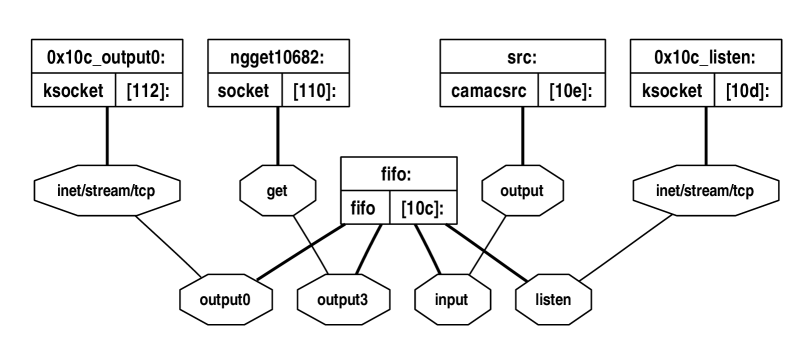
Rectangles are nodes with: name (up), type (left), ID (right);
Octagons are hooks named within.
ng_fifo has two output streams – remote through accept()ing ng_ksocket
and local through ng_socket, – as well as listen()ing ng_ksocket.
As we can see, at least three levels can contain
the same node type with slightly variated (by compiled–in or runtime
configuration) functionality, lets name it as
ng_fifo(4) (see
section 3.2.2). For example, CAMAC FEM level can
be implemented as pictured in Fig. 1: ng_camacsrc ng_fifo.
At the same time, SubEvB and EvB levels perform building of (sub)events, their
functionality can be implemented by the same ng_em(4)
(after qdpb’s event merger) node type (see section 3.2.3) with configurated
requests behaviour and (sub)event building rules.
Optionally, SubEvB and EvB levels
can contain software filters for (sub)event
rejection, which reasonably could be implemented by the same
ng_filter(4) node type (see
section 3.3.2) with configurated rejection rules.
So, the typical level layout (see Fig. 2) can look approximately
the following way:
ng_em ng_filter ng_fifo.
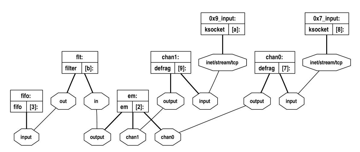
Legend the same as for Fig. 1.
ng_em has two input channels (chan0 and chan1)
from two data sources (for example, two crate controllers) on FEM level (see Fig. 1).
To simplify the picture, the ng_fifo outputs are not shown (see Fig. 1 for the typical ones).
Schematically the data packet flows in the Figure can be represented as follows:
ng_em launches ng_defrag(4) (see
section 3.2.1) nodes on each
configured input channel, while ng_defrag
launches client ng_ksocket, which connect()s to server
ng_ksocket of the upstream level. After that ng_em launches
kthread(9) to send the data requests (in the control
packet
form) to the upstream level according to the configured requests mode, and
to proceed (sub)events merging in accordance with the configured building rules.
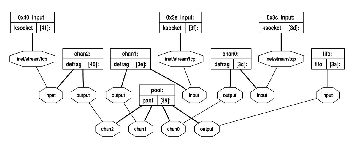
Legend the same as for Fig. 1.
ng_pool has three input channels (chan0, chan1, chan2)
from three data sources on EvB level (see Fig. 2).
To simplify the picture, the ng_fifo outputs are not shown (see Fig. 1 for the typical ones).
Schematically the data packet flows in the Figure can be represented as follows:
ng_fifo launches server
(listen()ing) ng_ksocket and handles accept()ing
ng_ksocket(s) as needed to serve requests from the downstream level.
The pool level client can be ng_em
in some specialized
mode (see also
section 3.2.3), or some separated multiplexer node
ng_pool(4) (see section 3.3.1).
The pool level filter can be a node ng_filter(4) with
assistance of the user context process222
Because it is very problematic to link into kernel a C++ code in general
and ROOT classes with their dictionaries in particular.
b2r(1) (see also
section 3.3), or only this process.
Anyway this filter should produce ROOT Event class instance for
each full event data packet obtained, and convert each Event
into the so called sequential (or serialized) form using the corresponding
Streamer() function(s).
Technically speaking, b2r(1)
should use the ROOT TBufferFile class instance to do so.
After that the sequential form of Event has length
fBufCurfBuffer returned by TBufferFile::Length()
function, should be read at TBufferFile::fBuffer location,
prepended by packet header, and injected into netgraph again.
So, the pool level server can be a usual ng_fifo node which
works with serialized Events as with usual data packets, while the
typical level layout (see Fig. 3) can approximately look as
follows:
ng_pool ng_filter ng_fifo.
Of course, we should note two additional crossings of context boundaries in this scheme: from the kernel to the user context and back again, which can be impractical due to too high CPU and memory consuming.
3.1 qdpb inspired entities and imported elements
Some ngdp ideas and entities (see also
[3]) are inspired by the ones previously designed for the
qdpb [1].
We import also the packet implementation and packet
type support from qdpb and redesign them in some aspects.
qdpb’s writer(1) utility for the packet stream
writing into a regular file(s) on HDD can be used “as is” – if
it is recompiled to be aware of
such changes.
Lets note that in principle any user context
utilities previously implemented for qdpb,
are still usable under ngdp, too, until
they satisfy the same condition.
3.2 Transport subsystem
As it has been
experimentally checked, a datagram size large enough
for (local) atomic transfer through netgraph(4) system
can be tuned easily. However, due to TCP/IP333
We can’t use UDP/IP for many reasons, the most important of which is the
following: UDP/IP does not support datagram fragmentation while the atomic
datagram size is limited by IP packet size (64 kbytes) which generally is
too small for our purposes.
and Ethernet444
Ethernet has a standard frame length mtu bytes.
network nature the
sender side unavoidably
fragments our packets, so, we should reassemble (defragment) them after
ng_ksocket(4) on the receiver side. For this
defragmentation it is enough to have
information from the packet header. Generally speaking, we have the
following options to implement a packet defragmenter:
- 1.
-
2.
to provide special KLD module with kernel–wide implementation of the reassembling code for the nodes mentioned above;
-
3.
to provide special node type ng_defrag(4).
The latter option is the most straightforward and in a modular netgraph(4) style, it does not waste memory by the duplicated code, and introduces neither additional defragmenter interface nor KLD dependencies.
3.2.1 ng_defrag(4) node
According to one of the packet defragmenter implementation
options (see
above) we implement the first version of the packet defragmenter code using
the node of the type, which
obtains data through input hook;
accounts their size (octets) and number of data messages
(frames);
defragments they into packets;
accounts a size (bytes) and number of
resulting packets (packets) as well as reassemble failures
(fails) and bytes rejected during failures (rejbytes);
stores completed packets and fragment of the last one into the circle buffer;
synchronously sends
the completed packets through the optional hook output (if exists) or
discards them. In case of the output counterpart slower than the input one,
the node drops the packet(s) and accounts the number of
drop(s) occured (droppacks).
This node understands the generic set
of control messages and the following specific control messages as well:
getclrstats – returns the current statistics (values of octets,
frames, bytes, packets, fails,
rejbytes and droppacks) and
clears it;
getstats / clrstats – returns / clears the current
statistics (the same values);
flush – tries to send all the packets not sent yet
from the circle buffer.
The node supports only one hook named input and only one hook named
output simultaneously, and performs shutdown after all the hooks are
detached.
The node is transparent in the counterstream direction –
the data arrived through the output hook are sent “as is” through
the input hook.
Later we have improved this node to launch client
ng_ksocket, to connect() it to server
ng_ksocket of the upstream level, and to attach it
to the input hook. This ng_defrag(4) node
understands two additional
control messages:
connect <struct sockaddr addr> – supplies IP address/port (in the
same format
as understood by ng_ksocket(4) node) of the server to
connect() with;
needchknum <int8_t flag> – (re)sets flag, which means to apply
checknum()
for each reassembled packet if the flag is nonzero,
otherwise it is not applied.
3.2.2 ng_fifo(4) prototype
In order to implement node
ng_fifo(4) with buffer disciplines, described in
section 3, as a first step we implement
some prototype, which is able to:
spawn listen()ing ng_ksocket at startup;
spawn accept()ing ng_ksocket(s) at each connection
request (up to the configured maximum) from the known host(s)/port(s), and/or
accept the hook connect from the local netgraph ng_socket(s);
emit each data packet obtained on the input hook (or
internally generated
if such hook is absent) in response to request555
Lets call such output policy as LAZY in contrast
with ASAP (As–Soon–As–Possible).
(in the form of the control packet)
obtaining through only the same accept()ing ng_ksocket
or local ng_socket;
close accept()ing ng_ksocket at EOF notification
obtaining or connection losing.
Such functionality does not require
kernel thread usage,
however can neither respawn listen()ing ng_ksocket in case of
its shutdown due to some external or accidental reasons,
nor handle nontrivial internal errors during listen()ing
ng_ksocket initialization. The reason is impossibility of using
(at least with macroscopic timeouts) msleep(9) in the
context, where
netgraph(4) code is executed (usually one of the
swi(9) software interrupt threads). So, this additional
error handling requires kthread(9) usage and can
be implemented without ideological or technical problems.
The prototype supports universal queue discipline
“nNGO” (see Table 1), which is suitable for FEM,
SubEvB, EvB and pool level bufferization simultaneously and provides all
queue access kinds, which required to support
CTRL_NG_CLEAR
(with and without ptype argument),
CTRL_NG_GETPACK
(with and without ptype argument),
CTRL_NG_COPY1OFN(period, ptype), and
CTRL_NG_GETNTHPACK(pnum, ptype)
control packet types.
We implement this universal queue first of all as the user context model
tbuf_nNGO.c
and debug such model strongly, to be sure that this
implementation is working now.
The ANSW_* packet bodies contain one of the
following error codes as uint16_t value (see
Table 1) to provide more information to client nodes
(ng_em(4), ng_pool(4), etc.)
to make up a decision:
EMPTY (“n”, “N” and “O” buffer
operations666
Here only realistic (with ptype argument) buffer operations
“nNGO” (see Table 1) are mentioned.
) – buffer is empty now;
TYPENOTFOUND (all buffer operations) – requested packet type not yet
obtained;
NUMNOTFOUND (all buffer operations) – requested packet number not yet
obtained;
NUMNOTALREADY (“G” buffer operation) – requested packet number
already dropped from the buffer.
To simplify mkpeering in some situations, the
ng_fifo(4) node supports the creat hook, which can be
removed after the input or listen hook appears, however the
input hook can be used for mkpeering, too, if this is convenient.
The prototype understands the generic set of control messages as well as the
following specific
ones:
start/stop – allows/denies getting packets from the queue;
lstnaddr – sets
IP address and port to bind() our
listen()ing ng_ksocket;
addaddr/deladdr – adds/deletes network IP address and port from
which connection requests should be accept()ed by our
ng_ksocket;
getclrstats – returns the current statistics (numbers of
packets_out,
bytes_out and fails, elapsed and pure times) and
clears it;
getstats / clrstats – returns / clears the current statistics
(the same values).
3.2.3 ng_em(4) prototype
In order to implement a node
with ng_em(4) functionality, described in
section 3, as a first step
we implement some prototype, which is able to:
launch ng_defrag node at each configured input channel, which
launches client ng_ksocket node to connect() to the upstream
server corresponding to the channel;
send requests in the form of control packets according to the
working mode (one of “SubEvBt” or “EvBt”) that has been configured;
merge packets obtained on the input channels according to the
merging rules which have been configured.
Generally (with some simplifications) speaking, in the SubEvBt working mode
the prototype makes one loop over the configured merging rules (and corresponding
requests) array and launches the kernel thread (see kthread(9))
for each configured index, so each thread serves only its “own” request.
Each thread emits CTRL_NG_GETPACK(ptype) control packets (see also
Table 1) through the hooks of the involved
input channels. After that each thread waits for responses in the form of the
data packets (always means positive response) and/or answer packets (always
means negative response) up to obtaining all the required packets
or corresponding (regular) timeout expiration. If the answer packet(s) is
obtained, the thread analyses the error code(s) and
either cleans the input channel storages and sends the full request again, or
repeats request(s) in the failed input channel(s) (after
either the same or increased regular timeout).
If some input channel(s) does not respond at all before regular timeout
expiration, the thread analyses the state of the responded channels and
either repeats request(s) in the failed input channel(s), or cleans the input
channel storages and sends the full request again. The regular timeout can be
increased up to the limit only. If all the required data packets are obtained,
the prototype merges them into a resulting packet and sends it to the
output hook (if
any). After that the thread sets a regular timeout to the nominal value,
sends the full request again, and so on.
In the EvBt working mode the prototype makes one loop over the configured
requests array and launches the kernel thread to serve each configured index,
too. Each request has the so called trigger input channel and is handled in
two phases. In the first (Trig) phase each thread emits CTRL_NG_GETPACK(ptype)
control packet (see also Table 1) through the hook of the
trigger input channel and waits for a positive or negative response
up to obtaining one or corresponding (trigger) timeout expiration.
If the answer packet is obtained, the thread analyses the error code and repeats
the request after either the same or increased trigger timeout.
If the trigger input channel does not respond at all before the trigger
timeout expiration, the thread repeats the request and waits during the
increased trigger timeout.
The trigger timeout can be increased up to the limit only, too.
If the data packet from the trigger server is successfully obtained, the
prototype extracts number777
type is also extracted and
checked against
the resulting type of the corresponding merging rule.
from its body and goes to the second phase, which for each request index is
handled by the same thread as the first phase.
In the second (afterTrig) phase the thread emits CTRL_NG_GETNTHPACK(, ptype)
control packets (see also Table 1) through the hooks
of the involved input (other than trigger) channels using mentioned above
and waits for positive and/or negative responses up to obtaining all the
required packets
or regular timeout expiration.
After that the algorithm behaves
as it is described above for the SubEvBt mode.
Note that all these working modes require servers (ng_fifo nodes)
with the support of the corresponding queue disciplines (as described in
section 3).
Duties between the kernel thread(s) and synchronous parts of the prototype are
separated as follows: each
rcvdata() execution processes single packet, possibly calls
evmerge() or evclean(), and
either sets a special flag kth_need
and wakes the thread up, or not. So, the thread can be waken up by the external
event (ngdp packet or netgraph(4) control
message arriving, etc.) or after the timeout expiration. In the first case the
thread performs some actions according to kth_need flag value, and
sets the transition state flag kth2state. In the second case it
performs some actions according to the kth2state flag value and sets
it again. In the both cases the thread possibly calls sendreq() and
evmerge() or evclean(), and finally goes to
msleep(9) with the corresponding timeout again.
We implement such nontrivial ng_em(4)’s algorithm as single source able to be compiled for both the kernel context using kthread(9) – for production purposes, and the user context using pthread(3) – for debug purposes.
The scheme of the packet requests assumes that only the packets with equal
numbers can be merged.
Later we generalize this approach and introduce id mark – some entity
from the packet header to be compared (really subtracted)
for each two candidates for being merged. Up to MAX_ID of these
id marks can be configured. The first added id mark is compared first.
Comparison functions of all the configured ids should return zero to permit
merging. In the current packet header implementation it is reasonable to choose
the following header fields as id marks:
the packet number – id mark named "num", function cmp_num()
returns zero for equal packet numbers;
the time stamp – id mark named "tv", function cmp_tv() returns
zero if time stamps are closer than the supplied function argument arg
(in mksec).
The "num" id mark is added at startup (in the node constructor) to
provide the expected node behaviour by default.
To simplify mkpeering in some situations, the
ng_em(4) node supports the creat hook, which can be
removed after input<N> or output hook appearing, however the
output hook can be used for mkpeering, too, if this is convenient.
The prototype understands the generic set of control messages as well as the
following specific
ones:
getclrstats <char *inchan> – returns the current
statistics (values of packets_in, bytes_in and reqs)
and clears it for the input
channel named <inchan>;
getstats <char *inchan> / clrstats <char *inchan> –
returns / clears the current statistics
(the same values) for <inchan>;
getclrostats – returns the current statistics (values of
packets_out,
bytes_out and fails) and
clears it for the output hook;
getostats / clrostats – returns / clears the current statistics
(the same values) for the output hook;
flush – marks buffers of all the input channels as empty;
inchan <struct ng_em_cfgentry> – adds configuration
entry to introduce new input channel according to supplied
<ng_em_cfgentry> members: name of the input channel char *name,
trigger bit int8_t trig for it (for SubEvBt mode means
nothing), IP address struct sockaddr addr to connect, number of the
request
entry int8_t idx, request entry configuration struct emtbl
(see below), – and mkpeers needed ng_defrag nodes;
getinchan <char *inchan> – returns configuration of the <inchan>
input channel;
addcfg <struct ng_em_tblentry> – adds the request entry to the
already existing
input channel according to the supplied <ng_em_tblentry> members:
name of the
input channel char *name, trigger bit int8_t trig for it (for
SubEvBt mode means nothing), number of the request entry int8_t idx,
request entry configuration struct emtbl tbl with the
uint16_t in_type, uint16_t out_type, u_char order,
and u_char number mandatory members;
delcfg <struct ng_em_tblentry> – deletes the already existing request
entry of the input channel <name> by <idx> or (for
<idx> equals to -1) by tbl.in_type;
getreq <int8_t idx> – returns configuration of the full request
with number <idx>;
delreq <int8_t idx> – deletes configuration of the full request
with number <idx> (equivalent to do delcfg for each input
channel involved into such request);
connect <char *mode> – checks the already supplied input channels and
request entries configuration to operate in <mode> (valid are
"SubEvBt" or "EvBt"), removes the
unused input channels (if any) and connects the not yet connected
ng_defrag(s) to servers according to the current configuration;
start <int64_t num_of_reqs> – starts request sending by thread(s)
up to the <num_of_reqs> requests will be issued;
stop – immediately stops the request sending;
addcmp <struct ng_em_addcmp> – adds id mark comparison function
described by structure
<ng_em_addcmp>, which supplies the function name
char *name and arguments array union arg arg_arr[];
delcmp <char *name> – deletes id mark comparison function named
<name>;
clrcmp – clears whole id mark(s) configuration;
getcmp – returns the full current id mark(s) configuration;
gettrig – returns the full current configuration of the trigger input
channels (for SubEvBt mode means nothing);
setsubnames <struct ng_em_subnames> – sets naming style for
ng_defrag subnodes as defined by int8_t mode structure
member, which can be equal to the following values #defined in
ng_em.c:
SUBNAMES_NONE (does not name subnodes at all),
SUBNAMES_TYPICAL (names by corresponding inchan
name – startup default),
SUBNAMES_UNIQUE (uses the unique node ID in name),
SUBNAMES_PREF (prepends by the supplied string),
SUBNAMES_SUFF (appends by the supplied string),
where the
char *str member is a prefix or suffix used by the last two modes;
setsubtype <char *type> – sets node type is welcomed to
connect as input channel(s): default is "defrag", empty string
"" means any type can be connected, node types other than "defrag"
are not launched automatically by inchan control message, so it should
be followed by the explicit connect control message;
getsubtype – returns the current subnode type;
settimo <struct ng_em_settimo> – sets the timeout configuration according
to the supplied <struct ng_em_settimo> members: number of request entry
int8_t idx, base timeout value int32_t t_timo (in msecs) and the
timeout increasing limit factor int32_t t_f for the Trig phase (in
SubEvBt mode means nothing), the same for the afterTrig phase –
int32_t r_timo (in msecs) and int32_t r_f,
limit for the number of request failures int32_t r_max;
gettimo – returns the current timeout configuration as
<struct ng_em_settimo> for each existing request entry.
ng_em(4) prototype supports only one hook named
output simultaneously, and
is transparent in the counterstream
direction for debug purposes –
the data arrived through the output hook are sent “as is” through the
hook, which corresponds to the input channel with zero number.
3.3 Data processing subsystem
Lets consider the ngdp elements used for some data
transformations.
1. Pool of events – has the following implementation options:
Possible pool level layout can be described by the following graph
where
ng_pool(4) is ng_em(4) in
some specialized working mode, or some separately implemented node with a
very similar functionality.
This approach is impossible without assistance of the user context process(es)
b2r(1), which converts
each obtained packet into ROOT representation of the full event
(class Event)
and serializes them using class TBufferFile
instances. Bufferization of the serialized Events done by
ng_fifo(4) node. Additional double data copying
from the kernel to the user context and back again should be noted.
Some server (user context process), which obtains the data packets from a single input stream multiplexed by
ng_pool(4)888
It issues the corresponding control packets to
request data from the upstream (EvB) level.
, converts each packet
into ROOT representation of the full event
(class Event), maintains the memory based
“pool” of such events, and sends the events in the form of
TMessage ROOT class instances at client requests. This pool could
be a circle queue with two possible update policies:
lazy – by last reader, or contemporar – by data appearing on EvB.
2. ng_filter(4) – node provides the software filter
functionality for (sub)events rejection, possibly located between
ng_em(4) and ng_fifo(4) on SubEvB
/ EvB level.
3.3.1 ng_pool(4) prototype
Currently we decide to implement the pool level functionality by
ng_pool(4) node
separately from the
very similar ng_em(4). The first stage prototype is able
to:
launch the ng_defrag node at each configured input channel, this
node in its turn launches the client ng_ksocket node, which
connect()s to the upstream server corresponding to this channel;
send requests in the form of control packets;
transmit all packets, accepted in input
channel(s) according to the configured rules, through the output hook.
The prototype makes one loop over the requests
array and launches the kernel thread for each configured index.
Through the hook of each involved input channel each thread emits
CTRL_NG_COPY1OFN(ptype)
control packet (see also Table 1) and
waits for positive or negative responses
in the form of data or answer packet until the packet is
obtained or the corresponding timeout is expired.
If the thread obtains the answer packet in some input channel, it marks such
channel to be requested again after the timeout expiration.
If some input channel does not respond in any form during the full timeout,
the thread performs the request in this channel again.
If the prototype obtains the data packet in some input channel, it sends
this packet without changes to the output hook (if any), and emits the
request in this channel again.
Of course, servers (ng_fifo nodes)
with the support of the corresponding queue discipline (as described in
section 3) are required.
The algorithm described above like the one from ng_em(4)
(see section 3.2.3)
essentially requires to use kthread(9).
Using the same approach as mentioned for ng_em(4)
we can compile a single source
for both the kernel context
and the user context.
After a strong debug sessions in the both contexts we are sure to have worked
out ng_pool(4) algorithm
implementation now.
The prototype understands the generic set of control messages as well as
the following specific
ones:
getclrstats <char *inchan> – returns the current statistics
(values of data_packs, data_bytes, answ_packs,
answ_bytes, fails, refus and reqs) and
clears it for the input channel named <inchan>;
getstats <char *inchan> / clrstats <char *inchan> –
returns / clears the current statistics (the same values) for
<inchan>;
getclrostats – returns the current statistics (values of
packets_out, bytes_out and fails) and
clears it for the output hook;
getostats / clrostats – returns / clears the current
statistics (the same values) for the output hook;
addcfg <struct tbl> / delcfg <struct tbl> – adds / deletes
the request entry;
getconf – returns the full current request configuration;
inchan <struct ng_pool_cfgentry> – adds the configuration
entry to introduce a new input channel and
mkpeers needed ng_defrag node;
connect – connects ng_defrag(s) to servers and
launches/terminates threads according to the current configuration of the
input channels and request entries;
delinchan <char *name> – disconnects (if needed) and deletes the input
channel named <name> (node should be in the stop state);
start <struct ng_pool_start> – starts request sending by thread(s)
with supplied <idx> up to the <num_of_reqs> requests will
be issued,
<idx> equals to -1 activates all configured thread(s);
stop <int8_t idx> – immediately stops the request sending by thread
with <idx>;
allow <disposition> – (re)sets allow/deny disposition of the input
channels according to the supplied <disposition> array of
int8_t: positive values mean to allow the packet
obtaining, negative – to deny, zero – not to change;
getallow – returns the current allow/deny disposition for all the
configured input channels;
settimo <struct ng_pool_timo> / gettimo – sets / returns the
nominal timeout (in msecs) and multiplier values.
ng_pool(4) prototype supports only one hook named
output simultaneously.
ng_pool(4) prototype transparent in the counterstream
direction for debug purposes – the
data arrived through the output hook are sent “as is” through the
hook, corresponding to the input channel with zero number.
3.3.2 ng_filter(4) prototype
As a first step of implementation a node
with ng_filter(4) functionality described in
section 3.3, some prototype is released, which is able to:
insert itself between two already connected
foreign hooks, using two own hooks, in and out;
restore the situation before insertion;
stay without any hooks to allow another insertion(s);
connect external
filter implementation – (pipe of) user context process(es)999
F.e., ngget filter subout | b2r -O | ngput filter subin .
or (chain of) netgraph node(s) – using two additional hooks,
subout and subin;
filter nothing (dummy internal filter procedure).
For initial mkpeering of ng_filter(4) a
specialized hook creat should be used, which will be removed automatically
after successful insertion (or can be removed manually at any time).
The prototype supports the following specific control messages:
getclrstats – returns the current statistics
(in_packets, out_packets, in_bytes,
out_bytes values) and clears it for each of
in, subout, subin and out hooks;
getstats / clrstats – returns / clears the current statistics
(the same values);
insert "<path1>/<path2>" – breaks the existing connection and
connects the own in hook to hook, represented by <path1>, and
the own out hook – to <path2>;
bypass – removes itself and reconnects peer hooks as it was before
the last insertion.
At the same time
the in (out)
hook can be created separately from the out (in) hook during
the usual mkpeer or connect procedures. Note, however, that
rmhooking of the in (out) hook leads to removing the
out (in) hook, too, without peer hooks reconnection101010
Due to netgraph(4)’s nature of the hook disconnection.
, that is why ng_filter(4)’s hook removing should be
avoided. In contrast, ng_filter(4)’s shutdown sequence
performes such reconnection graciously before the node is over.
As the next step we implement some kind of “plug–in” mechanism which
allows us to load and unload the internal filter procedures implemented as KLD
modules during the ng_filter(4) node runtime.
Namely, the filter procedure
under the
name xxx should be by convention
in the KLD module named
flt_xxx stored in the file flt_xxx.ko . This module
should contain a void *flt_xxx_ptr variable which points to
struct ng_filter_flt flt_xxx_arr[] – container for one or more
filter function111111
Prototyped as int (*fltfunc_t)(item_p, union arg *) .
pointer(s) as well as argument(s), name(s) and some flags. So after
fresh mkpeering the ng_filter(4) node instance
appears without any filter procedures. After that any filter
procedure(s) can be registered by the addflt control message (see below)
at any time. This leads to corresponding KLD module loading (if not yet) and
filter adding (if not yet) at the end of the filter procedure chain. For each
netgraph(4)’s item obtained from the in
hook each chain member will be applied sequentially, starting from the beginning
of the chain, up to the first nonzero procedure return or chain end. In the former
case the item is freed, in the latter it passes through the out
(or subout, if any) hook. Each item from the subin hook
(if any) passes untouched through the out hook. Any filter procedure
can be deregistered by the delflt control message (see below) at any
time, which leads to filter deleting from the filter procedure chain and the
corresponding KLD module unloading (if no longer referred to by anybody).
The following specific control messages were added:
addflt <struct ng_filter_addflt> – adds the filter procedure with
supplied name
<char *name> as the last procedure of the filter chain and fills the
array
of its arguments from the supplied <union arg arg_arr[]>;
delflt <char *name> – removes the filter procedure named <name>
(if any) from the
filter chain and unloads the corresponding KLD module if no longer used
by other instance(s) of ng_filter(4);
getflt – returns the array of <struct ng_filter_addflt> (the full
filter chain configuration);
clrflt – clears the whole filter chain.
As it has already been mentioned, the user context process participation in
filtering
will be unavoidable in some cases (f.e., events conversion to ROOT
representation). To allow a more efficient way for the packets to cross the
context boundaries twice – from the kernel to the user and back again – the
ng_mm(4) node
can be applied.
This node can be connected
to ng_filter(4) subout and subin hooks
by its in and out hooks, correspondingly. A user context process
can map the both buffers (for raw and converted
packets) into the own address space by mmap(2) mechanism,
supported by ng_mm(4)’s /dev/mmr<N>
and /dev/mmc<N> devices. After that the process can directly
communicate121212
This also eliminates possible packet fragmentation by
ng_socket(4) as well as socket I/O buffer size issues.
with these buffers as with regular pieces of memory. Of course,
some synchronization is required and can be done by calling
ioctl(2) to such devices before and after the buffer
reading and writing.
3.4 User context utilities
To simplify the data exchange between the user and kernel context entities of the ngdp system, the ngget(1) and ngput(1) utilities are implemented. A standard netgraph(4)’s way to do such exchange is to communicate through ng_socket(4) node, which at the same time is a socket in the specific domain. However, for speed reasons we have also implemented ng_mm(4) node, which at the same time is a UNIX device with support of the mmap(2) mechanism. This provides us the option to read the packets from the circle buffers allocated in the kernel directly and write them there, instead of flowing the packets through a number of layers of the socket machinery. The ngget(1) and ngput(1) are able to use both ng_socket(4) and ng_mm(4) mechanisms. The ngget(1) reads the packets from the kernel graph and writes them to the standard output. The ngput(1) reads the packets from the standard input and writes them to the kernel graph.
4 Conclusions
Using the netgraph(4) system we have demonstrated a possibility of implementing the data transportation and processing framework ngdp for the DAQ system building. The ngdp is as modular, lightweight and fast as possible under an ordinary UNIX–like OS. Several kernel context modules and user context utilities for the ngdp system have been designed, implemented and debugged.
References
-
[1]
Gritsaj K.I., Isupov A.Yu.
A Trial of Distributed Portable Data Acquisition and Processing
System Implementation: the – Data Processing with Branchpoints.
JINR Commun. E10–2001–116. Dubna, 2001. 19 p.
-
[2]
Brun R., Rademakers F.
ROOT – An Object Oriented Data Analysis Framework //
Proc. of the AIHENP’96 Workshop, Lausanne,
Switzerland, 1996.
NIM A. 1997. V. 389. P. 81–86.
-
[3]
Isupov A.Yu., Kovtun V.E., Foshchan A.G.
Implementation of data acquisition systems for multichannel nuclear
physics setups on base of the Unix–like operating systems (in Russian) //
The Jour. of Kharkov National Univ., phys. series “Nuclei,
particles, fields”. 2009. V. 845. No. 1(41). P. 93–107.