Loss of halo triaxiality due to bar formation
Abstract
Cosmological -body simulations indicate that the dark matter haloes of galaxies should be generally triaxial. Yet, the presence of a baryonic disc is believed to alter the shape of the haloes. Here we aim to study how bar formation is affected by halo triaxiality and how, in turn, the presence of the bar influences the shape of the halo. We perform a set of collisionless -body simulations of disc galaxies with triaxial dark matter haloes, using elliptical discs as initial conditions. Such discs are much closer to equilibrium with their haloes than circular ones, and the ellipticity of the initial disc depends on the ellipticity of the halo gravitational potential. For comparison, we also consider models with initially circular discs, and find that the differences are very important. In all cases, the mass of the disc is grown quasi-adiabatically within the haloes, but the time-scale of growth is not very important. We study models of different halo triaxialities and, to investigate the behaviour of the halo shape in the absence of bar formation, we run models with different disc masses, halo concentrations, disc velocity dispersions and also models where the disc shape is kept artificially axisymmetric. We find that the introduction of a massive disc, even if this is not circular, causes the halo triaxiality to be partially diluted. Once the disc is fully grown, a strong stellar bar develops within the halo that is still non-axisymmetric, causing it to lose its remaining non-axisymmetry. In triaxial haloes in which the parameters of the initial conditions are such that a bar does not form, the halo is able to remain triaxial and the circularisation of its shape on the plane of the disc is limited to the period of disc growth. We conclude that part of the circularisation of the halo is due to disc growth, but part must be attributed to the formation of a bar. Bars in the halo component, which have been already found in axisymmetric haloes, are also found in triaxial ones. We find that initially circular discs respond excessively to the triaxial potential and become highly elongated. They also lose more angular momentum than the initially elliptical discs and thus form stronger bars. Because of that, the circularisation that their bars induce on their haloes is also more rapid. We also analyse halo vertical shapes and observe that their vertical flattenings remain considerable, meaning that the haloes become approximately oblate by the end of the simulations. Finally, we also analyse the kinematics of a subset of halo particles that rotate in disc-like manner. These particles occupy a layer around the plane of the disc and their rotation is more important in the spherical halo than in triaxial ones. We also find that, even though the final shape of the halo is roughly independent of the initial shape, the initially triaxial ones are able to retain the anisotropy of their velocity dispersions.
keywords:
methods: -body simulations – galaxies: evolution – galaxies: haloes – galaxies: kinematics and dynamics – galaxies: structure1 Introduction
The vast majority of papers studying bar formation and evolution use idealised galaxy models with an exponential, or near-exponential, disc and a spherical halo. Yet, already in the nineties, cosmological -body simulations had shown that dark matter haloes are generally non-spherical, with a tendency to be more prolate than oblate (Frenk et al., 1988; Dubinski & Carlberg, 1991; Warren et al., 1992; Cole & Lacey, 1996). Later simulations (Jing & Suto, 2002; Bailin & Steinmetz, 2005; Allgood et al., 2006; Novak et al., 2006) have a sufficiently large number of particles to allow an adequate statistical analysis of the halo properties. Typically it is found that such haloes have isodensity axis ratios of and , depending on the mass of the halo and on the details of the cosmological simulations. In particular, more massive haloes tend to be more triaxial (or rather, prolate). This is presumably due to the fact that massive haloes undergo a larger number of merging events, which take place non-isotropically, along preferred directions linked to the filaments of the global large-scale structure. Furthermore, the axis ratios show some radial dependence and the triaxiality is usually found to increase towards the centre, as seen by Hayashi, Navarro & Springel (2007) who measured the shapes of the isopotential surfaces of cosmological haloes.
Simulations of large scale structure used to be restricted to dark matter, ignoring the baryonic component, due to the computational cost. More recently, cosmological simulations that include gas and the treatment of several physical processes (such as star formation, gas cooling, chemical enrichment and supernova feedback) have been able to form discs. And it is found that haloes tend to become axisymmetric due to the disc (Kazantzidis et al., 2004; Tissera et al., 2009). Thus a halo which contains a baryonic disc is expected to be less triaxial than a pure dark matter halo. Indeed, observational constraints on halo shape find that present-day haloes are very mildly elongated on the plane of the disc, or even consistent with an axisymmetric potential (Trachternach et al., 2008). This is also reflected on the statistics of disc galaxy shapes (Lambas, Maddox & Loveday 1992; Fasano et al. 1993; Rix & Zaritsky 1995; Ryden 2004, 2006), whose ellipticities are small compared to the ellipticities of haloes from cosmological simulations.
The shapes of discs are deformed by the aspheric halo potentials, such that in the equilibrium configuration the discs should be generally elliptical. At the same time, the presence of the disc acts to oppose the halo ellipticity on the plane (Jog, 2000; Bailin et al., 2007), since the disc elongation is perpendicular to the halo elongation. The interplay of the baryonic disc with its halo should somehow reconcile the highly triaxial shapes of pure dark matter haloes from cosmological simulations with the near circularity of present-day observed galaxies.
Such disc galaxies may develop bars, whose dynamics must be influenced both by the non-circular disc and the non-spherical halo. In order to investigate the effect of a triaxial halo on bar formation, Gadotti & de Souza (2003) performed -body simulations of a spheroid embedded in a rigid triaxial halo potential. In their simulations, the spheroid was distorted into a bar-like structure, due to the halo triaxiality.
The effects of a cosmological setting were studied by Curir, Mazzei & Murante (2006), who embedded circular discs in the haloes of cosmological simulations. They argue that the large scale anisotropies of the mass distribution influence the bar strengths and details of bar evolution, due to the continuous matter infall and substructures in the halo.
With simulations of considerably higher mass resolution, Berentzen, Shlosman & Jogee (2006) examined the effect of mildly triaxial haloes on bar evolution. In two of their three simulations with a live triaxial halo, they found that the bar quickly dissolved. The third case had a very massive and very mildly triaxial halo. In particular, its isopotential axis ratio in the equatorial plane is about 0.9. It this last case the bar does not dissolve.
Berentzen & Shlosman (2006) performed -body simulations in which they grew circular seed discs in assembling triaxial haloes, within a quasi-cosmological setting. The final shape of the halo depends on the mass of the disc, but not on the timescale of its growth. They show that massive discs completely wash out the halo prolateness and then develop long-lived bars, whereas discs that contribute less to the rotation curve are less efficient in axisymmetrising their haloes. They claim that in less massive discs, the bar instability is damped by the halo triaxiality.
Heller, Shlosman & Athanassoula (2007) investigated the formation of discs by following the collapse of an isolated cosmological density perturbation. They include star formation and stellar feedback in their simulations, so that a baryonic disc forms inside the assembling dark matter halo. The halo triaxiality is decreased in their models during disc growth. Bars that are formed early decay within a few Gyr, but such bars are driven by the prolateness of the halo and do not follow the usual bar instability evolution. Also, they find that the tumbling of the triaxial halo figure is insignificant.
Widrow (2008) used the adiabatic squeezing method of Holley-Bockelmann et al. (2001) to produce triaxial halo models, which he applied to a study of F568-3. This work was focused on a study of the rotation curve of this galaxy and did not discuss the reasons for the changes of the halo and disc shapes. Debattista et al. (2008) carried out control simulations in which a rigid disc was adiabatically first grown and then evaporated and found that the haloes were substantially rounder when the disc was near full mass, but that they returned to their initial shape after the disc was evaporated. The main goal of this paper and of its sequel (Valluri et al., 2009) was to search for the changes of orbital structure that could account for the changes of halo shape due to the baryonic component.
In the present work we continue along the lines of the above mentioned work and particularly investigate bar formation and evolution in triaxial haloes and the corresponding effects on the halo properties. Does the triaxiality of the halo inhibit bar formation, or change drastically the bar properties? Or, alternatively, are strong bars able to form inside triaxial haloes and then cause them to lose their remaining triaxiality? We investigate different models and different types of initial conditions. As initial conditions, we use elliptical discs which are designed to be in equilibrium with the elliptical potential of the halo and compare the results with those obtained with the more straightforward, but out of equilibrium, initially circular discs. We also focus on evaluating the separate effects of two factors that contribute to changing the halo shape: the growth of the disc mass, and the formation of a bar.
In Sect. 2 we present our initial conditions and in Sect. 3 we discuss bar growth and compare the results in initially axisymmetric and in initially elongated discs. In Sects. 4 and 5 we consider different halo core sizes and different time-scales for disc growth, respectively. In Sect. 6 we present a series of simulations, made in order to distinguish how much of the evolution of the halo shape is due to the introduction of the disc and how much to the growth of the bar. Vertical shapes are the subject of Sect. 7. In Sect. 8 we consider the effect of triaxiality on halo kinematics. Finally we summarise and conclude in Sect. 9.
| halo | ||
|---|---|---|
| 1 | 1.0 | 1.0 |
| 2 | 0.8 | 0.6 |
| 3– | 0.7 | 0.5 |
| 3 | 0.6 | 0.4 |
| 3+ | 0.5 | 0.3 |
2 Initial conditions
2.1 Halo initial conditions
| (1) | (2) | (3) | (4) | (5) | (6) | (7) | (8) | (9) | (10) |
|---|---|---|---|---|---|---|---|---|---|
| name | halo | disc shape | Q | major axes | disc | ||||
| 1C | 1 | circular | 1 | 5 | 0.5 | - | 100 | live | |
| 2C | 2 | circular | 1 | 5 | 0.5 | - | 100 | live | |
| 3C | 3 | circular | 1 | 5 | 0.5 | - | 100 | live | |
| 2E | 2 | elliptical | 1 | 5 | 0.5 | perpendicular | 100 | live | |
| 3E | 3 | elliptical | 1 | 5 | 0.5 | perpendicular | 100 | live | |
| 1’C | 1 | circular | 1 | 5 | 5.0 | - | 100 | live | |
| 2’C | 2 | circular | 1 | 5 | 5.0 | - | 100 | live | |
| 3’C | 3 | circular | 1 | 5 | 5.0 | - | 100 | live | |
| 2’E | 2 | elliptical | 1 | 5 | 5.0 | perpendicular | 100 | live | |
| 3’E | 3 | elliptical | 1 | 5 | 5.0 | perpendicular | 100 | live | |
| 1C t10 | 1 | circular | 1 | 5 | 0.5 | - | 10 | live | |
| 2E t10 | 2 | elliptical | 1 | 5 | 0.5 | perpendicular | 10 | live | |
| 3E t10 | 3 | elliptical | 1 | 5 | 0.5 | perpendicular | 10 | live | |
| 1C t200 | 1 | circular | 1 | 5 | 0.5 | - | 200 | live | |
| 2E t200 | 2 | elliptical | 1 | 5 | 0.5 | perpendicular | 200 | live | |
| 3E t200 | 3 | elliptical | 1 | 5 | 0.5 | perpendicular | 200 | live | |
| 1Cm | 1 | circular | 0.3 | 5 | 0.5 | - | 100 | live | |
| 2Cm | 2 | circular | 0.3 | 5 | 0.5 | - | 100 | live | |
| 3Cm | 3 | circular | 0.3 | 5 | 0.5 | - | 100 | live | |
| 2Em | 2 | elliptical | 0.3 | 5 | 0.5 | perpendicular | 100 | live | |
| 3Em | 3 | elliptical | 0.3 | 5 | 0.5 | perpendicular | 100 | live | |
| 1C azi | 1 | circular | 1 | 5 | 0.5 | - | 100 | constrained | |
| 2C azi | 2 | circular | 1 | 5 | 0.5 | - | 100 | constrained | |
| 1C hot | 1 | circular | 1 | 5 | 0.5 | 2.4 | - | 100 | live |
| 2E hot | 2 | elliptical | 1 | 5 | 0.5 | 2.4 | perpendicular | 100 | live |
| 3E hot | 3 | elliptical | 1 | 5 | 0.5 | 2.4 | perpendicular | 100 | live |
| 1C rigid | 1 | circular | 1 | 5 | 0.5 | - | - | 100 | rigid |
| 2C rigid | 2 | circular | 1 | 5 | 0.5 | - | - | 100 | rigid |
| 3C rigid | 3 | circular | 1 | 5 | 0.5 | - | - | 100 | rigid |
| 3E 90 | 3 | elliptical | 1 | 5 | 0.5 | parallel | 100 | live |
The triaxial halo initial conditions for our simulations were created using the iterative method of Rodionov, Athanassoula & Sotnikova (2009), which creates equilibrium -body systems with a given mass distribution and, if desired, given kinematical constraints. In our case we did not wish to impose specific kinematical constraints, so we first adopted the desired mass distribution, as described below, and then found the corresponding kinematics so that the model is in equilibrium. For this we made a large number of successive evolutionary steps of small duration, and at the end of each such step brought back the mass distribution to the adopted density profile and shape, as described in detail in Rodionov et al. (2009). At the end of this sequence we obtain initial conditions which are both in equilibrium and have the desired mass distribution.
The initially spherical haloes have the density profile described in Hernquist (1993). They are then made triaxial by scaling the particle positions in the and directions by factors of and , respectively (). The iterative method is employed to obtain the velocities of an equilibrium configuration with such shape. The density profile of these triaxial haloes is described by:
| (1) |
where
| (2) |
is the mass of the halo, is a core radius and is the cutoff radius. The normalisation constant is defined by
| (3) |
where (Hernquist, 1993).
We employ in our simulations five haloes of different shapes: one spherical and four triaxial ones, with the initial axis ratios given in Table 1. All haloes have the same mass and cutoff radius . The core radius is for all models (except in Section 4, in which a different core size is explored). Haloes 1, 2 and 3 are used throughout the analysis, whereas the additional haloes 3– and 3+ are used mainly in Sect. 8.
The haloes (with no disc) were evolved for 800 time units (units in Section 2.3) to make sure that their shapes remain unchanged. Their axis ratios are independent of radius at the beginning of the simulations and remain so for 800 time units. The overall shape of the halo, taking all particles into account, remains constant with time for all models. We may also measure the shape using only particles in the inner region. In order to define this region, we proceed as follows. We choose a radius, which represents the size of the region we wish to study, in this particular case . We count the number of particles inside a sphere of radius . We sort all particles by density and define the inner region as the region occupied by the first particles of highest local density. In this way, we select an ellipsoidal shape (bounded by an isodensity surface) and avoid delimiting the inner region by radius, which would introduce a bias in the calculation of the shape (Athanassoula & Misiriotis, 2002). In the case of these pure haloes, however, the inner shape does not differ from the overall shape, and both are constant in time. Linear fits to the and of the pure halo models show that the axis ratios typically change with a slope of the order of to . This means that in a Hubble time (), the change in or is of the order of 0.1% to 1%. This holds for both the entire halo and its inner region.
In the case of halo 3, we observe a vertical instability of the type. When viewed on the plane, halo 3 develops a transient X-like structure in the beginning of the simulation. This instability is more pronounced if there is a disc, but it is also measurable in the pure halo model. The relative intensity of the Fourier component peaks at about but after that it strongly subsides in both cases.
2.2 Disc initial conditions
2.2.1 Epicyclic approximation to create elliptical discs
If a circular disc were to be introduced in a triaxial halo, it would be out of equilibrium. An elliptical disc whose shape is determined by the shape of the halo potential should be initially closer to equilibrium and thus more suitable as initial condition for the simulations. In order to set up the position and velocity coordinates for such an elliptical disc, we use the epicyclic approximation (Binney & Tremaine 1987; Gerhard & Vietri 1986; Franx, van Gorkom & de Zeeuw 1994). In the presence of a non-axisymmetric halo potential, the disc particles are expected to have non-circular orbits. This approximation tells us how elliptical each of these orbits ought to be. Ultimately, the departure from circularity of each orbit is determined by two quantities: the shape of the halo potential, but also its mass distribution (in the form of circular velocity, ) – both as a function of radius.
The first step is to create a circular disc with an exponential density profile:
| (4) |
where is the disc mass, is the scale length of the disc and is the scale height.
The elliptical disc will have an ellipticity of the orbits and an ellipticity of the velocities (ellipticities are defined as ), both of which have a radial dependence. Because the epicyclic approximation does not take height into account, the vertical coordinates will remain unchanged, and the and coordinates of the disc will be altered independently of . The position coordinates on the plane are reassigned as follows:
| (5) |
| (6) |
where are the position coordinates of the particles of the circular disc and are the position coordinates of the particles of the new elliptical disc. Similarly, the velocity coordinates will be:
| (7) |
| (8) |
where is the circular velocity, is the radial velocity and the tangential velocity. The ellipticities of the velocities, of the positions and of the potential can be shown to have a simple dependence:
| (9) |
Besides, it is possible to show that the ellipticity of the orbit, , is related to the ellipticity of the potential through:
| (10) |
which is a generalisation for any of the particular case employed by Franx et al. (1994), where the circular velocity was a power law.
So, for a given triaxial halo, we measure the ellipticity of the potential as a function of radius. Then, measuring and estimating its derivative allows us to calculate the ellipticity of the orbits for each disc particle. The particles in the disc have orbits whose ellipticities are not constant with radius even if the ellipticity of the halo potential is. The epicyclic approximation, however, is not valid when is approximately proportional to , and for this reason it can not be applied to the innermost part the disc. To prevent it from diverging, is set to a constant value in the innermost region.
The initial shapes of the halo potentials are quite independent of radius and correspond to ()pot of approximately 1, 0.85 and 0.72 for haloes 1, 2 and 3, respectively. The axis ratios of the potential are expected to be larger than the axis ratios of the density because the isopotential contours (since they refer to an integrated quantity) are always smoother and more circular than the isodensity contours. In order to measure the axis ratios of the potential, the halo particles are sorted by potential and the components of the inertia tensor are calculated in consecutive intervals containing equal number of particles. The ()pot is obtained for each interval, interpolated to the disc particle positions and used to calculate and for each disc particle. The resulting shapes of the discs are seen in the upper row of Fig. 1. In equilibrium, the orbits of the disc particles will be elongated in a direction perpendicular to that of the halo major axis, and this comes out naturally from the epicycle approximation. Besides creating elliptical discs, for comparisons, we also create equivalent models using circular discs in each of the triaxial haloes (Table 2).
2.2.2 Growing the disc
Instead of introducing the disc abruptly, we slowly grow the mass of the disc while the system evolves. This is done by gradually increasing the mass of each disc particle from (almost) zero to , according to a smooth curve:
| (11) |
where is the final mass of the disc, is the number of disc particles and is the growth time of the disc mass. This procedure is applied for an interval of 100 time units, during which time both the halo and the disc are live. In the models described in Sect. 5 other growth times are explored.
At first, the disc particles are very light and they feel the halo potential and respond almost as test particles, without much self gravity and without affecting the halo abruptly. At the disc is at full mass and, in some respects, this is the instant that ought to be regarded as the actual beginning of the simulation, since before this time both the total mass of the system and its total angular momentum are in fact increasing.

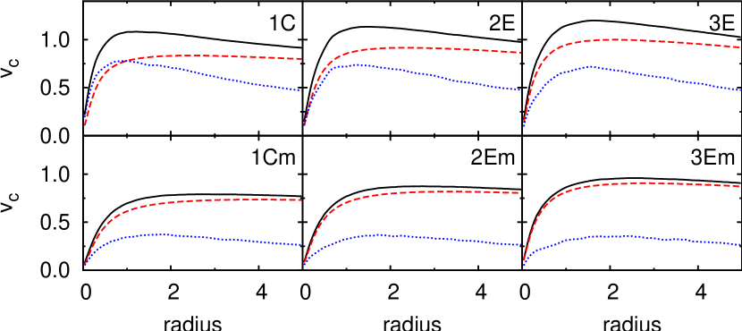
When the mass of the disc has finished growing () the contributions of the disc and halo to the total circular velocity are comparable in the inner region, for the spherical case (1C). In the more triaxial model (3E), however, the halo is stronger even in the inner region. One of the reasons for this is that the discs are not identical in the three models. The (azimuthally averaged) rotation curve of the more elliptical disc (model 3E) is slightly lower in the very centre, if compared to that of the circular disc in model 1C. Another reason for the different rotation curves is the fact that the density of the triaxial haloes is slightly higher in the centre if compared to the spherical halo. As can be seen in Fig. 3, the density profiles at (solid lines) are already slightly larger in the centre for the triaxial haloes, because they are made triaxial by shifting the and coordinates of the particles by factors smaller than one, which causes the concentration of mass in the centre to increase. Apart from this fact, the inner halo density suffers a further small increase (in all three models) due to the introduction of the disc, presumably because the mass of the disc drags halo matter towards the equatorial plane. This is why at (dotted lines in Fig. 3) there has been a systematic increase of the density in the innermost regions accompanied by a very mild but systematic density decline for . At the halo density profiles of the three models are roughly similar, meaning that the initial differences in their inner densities were compensated by the growth of the disc mass. So, as far as halo density profiles are concerned, the three haloes are more similar at than they were at . For clarity, further times are not shown in Fig. 3, but from to the changes are insignificant.
Using the isothermal sheet approximation, the vertical component of the velocity dispersion, , is determined by :
| (12) |
where is the surface density. The velocity dispersions in the other two coordinates are acquired spontaneously by the disc during its evolution, while its mass grows. Because of this method of growing the disc, where the velocity dispersions are gradually acquired by the evolving disc, we do not set a particular Toomre parameter to begin with. By measuring the epicyclic frequency and the surface mass density we find that the values of for models 1C, 2E and 3E, averaged over the radius, are in the range of 0.7 to 1.1, between and . It should be noted that the radially averaged values are meant as a rough estimate, since the radial dependence of is considerable. At later times the bar grows and the potential becomes strongly non-axisymmetric, so that the standard definition of is not very meaningful.
2.3 Miscellanea
The units used here are such that the Newtonian gravitational constant is and the scale length of the disc is . Furthermore, for the standard sequence of models . In physical units, if we take the disc scale length to be 3.5 kpc and the mass of disc M⊙, for example, then the unit of time is yr and the unit of velocity is 248 km/s.
The models here are evolved for 800 units of time, which, in the above example, corresponds to 11.2 Gyr. In these simulations, the halo has particles and the disc particles. The mass of the halo is always and, for the standard models, the mass of the disc is . The evolution is calculated using the -body code gyrfalcON (Dehnen, 2000, 2002). In all cases, we used a softening of 0.05 units of length, an opening angle of 0.6 and a time step of 1/64 units of time. This led to an energy conservation of the order of 0.1%.
We calculate the and axis ratios using the eigenvalues of the inertia tensor. If the shapes are measured in circular shells with equally spaced radial bins, a strong bias towards sphericity is introduced. Instead, we sort the halo particles as a function of local density and we measure the shape inside density bins containing equal number of particles, as already described in Sect. 2.1. These bins are not necessarily spherical and they are not equally spaced in radius.
In order to measure the strength of the bars, we use the Fourier components of the bidimensional mass distribution as a function of cylindrical radius, computed in the following way:
| (13) |
| (14) |
where is the number of particles inside a given ring and is the mass of each particle. The relative amplitude is defined as:
| (15) |
The ‘bar strength’ is the quantity (for ), and the integration is done until a maximum radius , which is typically where the amplitude of the component reaches a minimum.
3 Loss of halo triaxiality due to elliptical or circular discs
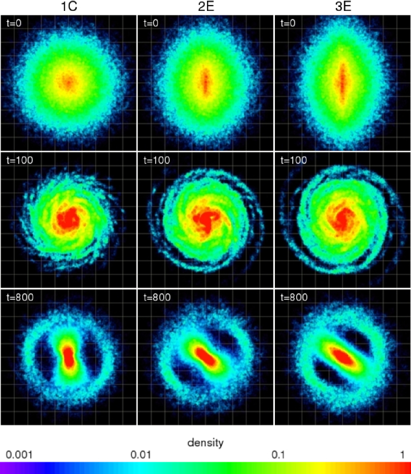
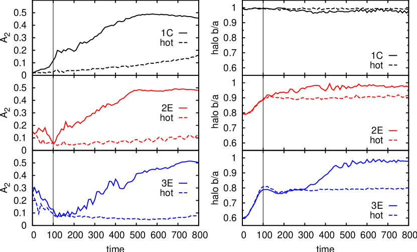
As described above we introduce the disc gradually over 100 time units and then continue the fully self-consistent simulation to follow the evolution. The most striking difference with respect to the pure halo models is that the haloes in which (massive, bar-forming) discs are grown lose at least some of their triaxiality (Fig. 4). The effects on the vertical flattening are presented in Sect. 7.1. Except for that section, expressions such as ‘circularisation’ and ‘loss of triaxiality’ refer to the face-on shape of the halo, i.e. they both mean that the halo becomes circular on the disc equatorial plane of the disc ( approaching 1), regardless of .
3.1 Standard models and models with initially circular discs
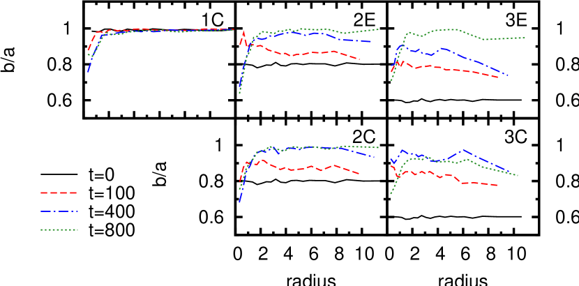
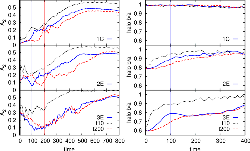
In all models where (bar-forming) discs were grown, the haloes had their shapes altered. Even in the case of a spherical halo with circular disc (1C) the innermost region of the halo becomes rather prolate, due to the formation of the bar: this is the “halo bar” (Athanassoula, 2005a, 2007), or “dark matter bar” (Colín, Valenzuela & Klypin, 2006), which rotates together with the disc bar, but is less elongated and less strong. The formation of such a structure causes the halo to reach 0.8 in the inner region (Fig. 5) in all models where the disc forms a strong bar. Further out, the initially triaxial haloes (models 2 and 3) lose their triaxiality almost entirely after 800 time units. Roughly, almost half of the loss takes place during disc growth (from solid to dashed lines in Fig. 5) and the second half takes place due to bar formation and evolution (from dashed to dotted lines in Fig. 5). This is approximately valid also if circular discs are used instead of elliptical discs, but there are interesting differences which will be discussed.
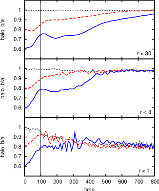
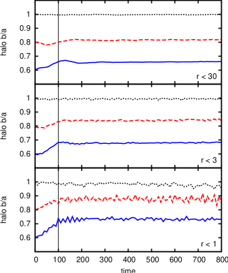
The time evolution of the shapes of models 1C, 2E and 3E are shown in Fig. 6. These are the standard models, because each of the three haloes contains its equilibrium disc. The variations with circular discs (2C, 3C) will be used for comparisons. The halo are measured within three different radii. First, they are measured taking all particles into account. To measure the shape within a given radius , we employ the procedure already described in Sect. 2.1. This is done for and . Measuring the shapes in this fashion highlights respectively: the overall shape (all particles), the shape at the region where most of the disc mass is located () and the shape in the region of the bar ().
As can be seen in Fig. 6, the shapes of the haloes in models 1C, 2E and 3E all tend to be same at , the region of the disc () approaching circularity faster than the outer halo. This is presumably due to the fact that the dynamical time is much longer in the outer parts than in the region with . In , all models develop the same halo bar with . The evolution of the vertical flattening (discussed in Sect. 7.1) shows that even in the case of the spherical halo also drops to 0.8, which means that the halo bar is a prolate structure (1:0.8:0.8, the circular plane containing the shorter axes).
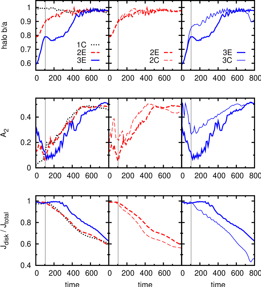
The comparisons of the central parts of models 1C, 2E and 3E (and also 2C and 3C) are shown in Fig. 7. On the first row the halo for is shown again for the three standard models and then separately for models 2 and 3 comparing their respective elliptical and circular discs. The more relevant difference is that for the case of the circular disc inside the more triaxial halo (3C): the halo gets circularised faster than in the case of the elliptical disc. During disc growth, the halo already increases more for the circular disc and, from then on, it remains always larger than that of model 3E, until about . The second row of Fig. 7 shows the evolution of the bar strengths. Bar strengths, given by the quantity (Eq. 15), are measured from to , because that’s approximately the first minimum of for all models with strong bars. For the standard models, we note that at first, our measure of actually decreases in the E cases. We point out that there is no actual bar at such times: the non-zero of models E is simply a measure of the non-circularity of the initial conditions, so that is in reality indicating the non-axisymmetry, or non-circularity of the disc. During disc growth this non-circularity is momentarily reduced, such that by all three models have roughly the same value. Subsequently, the actual bar instability sets in and a true bar grows in all three models, but with a delay in the case of 3E. If we then compare what happens in the models with circular discs and with elliptical discs, it turns out that, contrary to what one might have naively expected, the bar is actually stronger in the initially circular discs. It should be emphasised, however, that these discs cease being circular immediately after , because they are presumably driven by the halo into an excessively elliptical shape. At first, the values of the circular discs increases very sharply, to values considerably higher than even the initially elliptical discs. This behaviour is reminiscent of the transients and overshoots observed in bar response calculations when the bar is not inserted gradually. As a matter of fact, avoiding such unreasonable behaviour was precisely one of the motivations for setting up initial conditions for elliptical discs which should be in equilibrium. By the of the circular discs has decreased somewhat, but it is still higher than that of the elliptical discs. So by the time the bar begins to really form, it does so in a disc which is actually more elliptical than in the E models. The result is that in the C models, the bar is stronger than in the E models, during most of the evolution.
The fact that discs with stronger bars circularise the halo more is a first indication of the importance of bar formation and evolution in the loss of halo triaxiality. In models that form stronger bars, the axisymmetrisation of the halo is accomplished sooner. Comparing models 2E and 3E in Fig. 7, we see that during most of the time ( to or 500) the bar in 2E is stronger than in 3E. At the same time, has larger values. Similarly, in model 3, the E and C cases show that the bar of 3C is stronger during and also the halo is clearly more circular. In fact, the halo for 3E doesn’t even increase very much in . It only becomes steeper at , when the bar strength of 3E has finally caught up with values comparable to those of 3C.
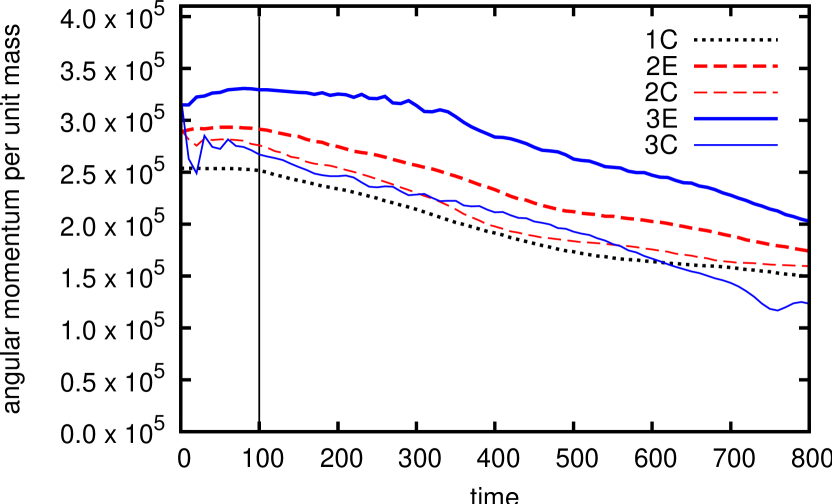
Another very important quantity in the evolution of these systems is the angular momentum, whose total values (per unit mass) are shown in Fig. 8. Each disc acquires a certain amount of angular momentum while it is growing, and this amount is not the same for all models. Thus the total angular momentum increases somewhat during a time equal to , but stays constant after that. There is, however, considerable angular momentum exchange between the disc and the halo component, as in models with axisymmetric haloes (e.g. Sellwood 1980; Debattista & Sellwood 2000; Athanassoula 2003; O’Neill & Dubinski 2003; Martinez-Valpuesta, Shlosman & Heller 2006; Villa-Vargas, Shlosman & Heller 2009). The net amount of angular momentum lost by the disc is gained by the halo in all models. At the halo has nearly zero angular momentum, so that roughly the total angular momentum of the system is with the disc. Later, as the bar begins to form, it gets redistributed. One important feature of these models is that the initially more elliptical discs acquire more angular momentum. This can be clearly seen if we compare models 1C, 2E and 3E, our standard sequence of models with equilibrium discs (thick lines in Fig. 8). And it can also be seen if we compare E and C discs for one given halo: the initially circular discs (thin lines) have less angular momentum than the equivalent initially elliptical disc in the same halo, or, equivalently, in E models, the disc has acquired more angular momentum by than in C models.

We may draw another similar observation from the lower panel of Fig. 7, which shows the fractional angular momentum of the discs. We see that aside from having more total angular momentum, the initially more elliptical disc will also hold a larger fraction of the total angular momentum of the system than the fraction that will be held by an equivalent circular disc, at any given time. This is valid for any one given halo. And it is still true if we compare the elliptical discs of the two triaxial haloes. The consequence of this is immediate: if a disc is holding on to its angular momentum, it means that it is not forming a bar so well. So the discs that don’t lose their angular momentum so efficiently will have smaller bar strengths. This is in good agreement with the results found for axisymmetric haloes, where a tight correlation can be found between the bar strength and the angular momentum gained by the halo and lost from the disc (Athanassoula, 2003).
So we might propose the following scenario: as they form, elliptical discs acquire a larger amount of angular momentum. Also, they don’t lose their angular momentum so efficiently and this causes them to develop weaker bars, which take more time to circularise their triaxial haloes.
One particularly interesting comparison between circular and elliptical discs is provided by models using halo 3+, which is more triaxial than halo 3. Halo 3–, being intermediate in shape between haloes 2 and 3, shows an evolution which is merely intermediate between those two cases. In the case of the very triaxial halo 3+, on the other hand, the difference between using a circular disc or an elliptical disc is drastic. Figure 9 shows the evolutions of and of halo for models 3C+ and 3E+. For the model with a circular disc (3C+), peaks strongly very early on () and then decays gradually to small but non-zero values. For the model with an elliptical disc (3E+), decreases at first and then starts growing in a manner similar to the other E cases, albeit with a considerable delay. Model 3C+ is the only one of our simulations in which halo triaxiality could be said to have inhibited bar formation. That, however, appears to be due to the inadequacy of using a circular disc as the initial conditions. When, instead, we use an elliptical disc in the same halo, a strong bar does form.
The evolution of halo shapes in models 3C+ and 3E+ (Fig. 9) shows that disc introduction causes some halo circularisation in both cases. It is also clear that in the case where there is bar formation (3E+), the halo suffers further circularisation and the period of more intense loss of triaxiality coincides with the period of faster bar growth. In the case where there is no significant bar formation (3C+), the halo is able to remain triaxial throughout. These results point to the contribution of the bar as one of the factors causing loss of halo triaxiality.
These results are also indications of very important differences that arise depending on whether one uses circular, and manifestly out of equilibrium discs, or elliptical, and near equilibrium ones, when simulating bar formation within triaxial haloes.
3.2 Elliptical disc parallel to the halo major axis
The equilibrium configuration for the system of an elliptical disc inside a triaxial halo is such that the major axis of the disc is perpendicular to the major axis of the halo. Therefore, in all our initial conditions the elliptical disc is oriented in this way. We, nevertheless, also explored one simulation in which the major axes of disc and halo are parallel, knowing that this would be well off equilibrium. We took model 3E and turned by the elliptical disc in the initial conditions (let us call it model 3E90). The result is that the evolution of this model is very similar to the evolution of model 3C. That is to say, in model 3E90 the bar is stronger than in model 3E. The angular momentum transfer is more steep and the circularisation of the halo takes place faster. As a matter of fact, the bar in model 3E90 is even slightly stronger than in model 3C, and thus the angular momentum is lost by the disc even faster and the halo consequently increases more rapidly. The disc in model 3E90 behaves much in the same manner as the disc of 3C in the beginning of the simulation: it becomes excessively distorted in the direction perpendicular to the halo major axis. This confirms the general trend that a stronger bar will cause greater halo circularisation. It also indicates how strong the effect of out-of-equilibrium initial conditions can be, thereby stressing the importance of starting the simulation in near-equilibrium.
3.3 Position angles
In order to study the relative orientations of the various elongated structures, we distinguish between two regions of the disc and two regions of the halo, namely the inner and outer parts of each. We therefore define the following four components: the disc bar (), the halo bar (), the outer disc () and the outer halo (). Using models 1C, 2E and 3E we then measure the position angles of each of these components as a function of time, using the particles contained within those radii. The angles are obtained from the Fourier analysis, and correspond to the direction of the elongation of the component. The above definitions of the disc bar region and of the halo bar region take into account the typical lengths of these structures, that extend namely to about and . The definitions of the outer disc and outer halo are meant to give an estimate of the direction of the overall orientation of such structures, without being contaminated by the bars. The outermost parts of the halo retain some residual triaxiality which, although small, is sufficient to allow a reasonable determination of the direction of its major axis.
Once both are formed, the disc bar and the halo bar rotate together. The halo bar forms sooner in the spherical case, while in the triaxial cases, the formation of the halo bar is somewhat delayed. Once they are sufficiently strong, their position angles roughly coincide throughout the rest of simulation.
The orientation of the outer halo is ill defined in the spherical case. In the triaxial cases, the major axis turns very slowly. We find that it takes about 700 or 800 time units to turn by . Such slow tumbling was also obtained by Heller et al. (2007), after the period of collapse. This is also in good agreement with the results of Bailin & Steinmetz (2004), who measured the figure rotation of haloes from cosmological simulations and obtained pattern speeds with a log-normal distribution centred at approximately . This means that a typical halo would rotate roughly during a Hubble time.
The outer shape of the disc also bears some interesting relations to the bar. In the beginning of the simulation the elliptical disc is perpendicular to the major axis of the halo. At first, the position angle of the outer disc remains in the same direction. Gradually, after both bars are formed, the overall shape of the disc acquires figure rotation, with a pattern speed comparable to that of the bar but out of phase with respect to it. The phase difference between the disc bar and the outer disc is of at first, but then decreases.
4 Different halo core sizes
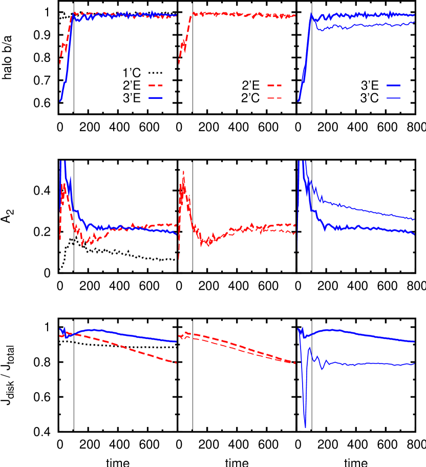
In spherical haloes it was found that the core radius is an essential feature in determining the evolution of the galaxy (Athanassoula & Misiriotis, 2002; Athanassoula, 2003). So far, we have only presented results from haloes with a small core (), of the type called MH in Athanassoula & Misiriotis (2002). In this section we will discuss the change of halo shape in simulations with large cores (, i.e. of the type called MD in the aforementioned reference). These models, named 1’C, 2’E, 3’E (and 2’C, 3’C), are the equivalent of the standard set 1C, 2E, 3E (and 2C, 3C) in the sense that they have the same shapes as the standard set. However, they have different density profiles, namely they are less concentrated. Evolved without discs, these haloes with are just as stable as the haloes with , as far as their density profile and shape are concerned, i.e. they retain their shapes and profiles until the end of the simulation.
Haloes with a large core have a peculiarity which causes the epicycle approximation to give worse results. Because the core is larger, the velocity curve is, at the start of the simulation, approximately linear () across a larger region. The epicyclic approximation breaks down in this case, which means that needs to be truncated at an arbitrary value over a good portion of the disc. In the spherical case, the disc is appropriately circular, but because of these difficulties, the disc shape is not set quite properly in the triaxial models of larger core. As a consequence we have some transients and overshoots: a disc which is not in equilibrium with its triaxial halo will respond to the ellipticity of the potential it feels by becoming excessively elongated at first, thus causing to increase too much. This also means that with such haloes, the behaviour of the elliptical discs are not much better than the circular ones in the same triaxial haloes.
The evolutions of halo , , and angular momentum for haloes with large cores are shown in Fig. 10. They show clearly that these haloes are more susceptible to circularisation. The disc growth alone is capable of driving the halo to 1 by in all cases. These now spherical, large-cored haloes don’t receive much angular momentum from their discs, and thus don’t develop strong bars. The fact that the departures from axisymmetry in models 2’ and 3’ are higher than in 1’ is mostly due to the fact that the discs in the initially triaxial haloes were driven to be excessively elliptical, even though some of the non-axisymmetry in 2’ can be attributed to the formation of a weak bar, that can be discerned on the snapshots. Moreover, there is some degree of angular momentum exchange.
The main result of this section is that less concentrated haloes are unable to retain their triaxial shape. The growth of disc mass inside such large-cored haloes is already enough to make them totally spherical. Furthermore, models with such haloes do not develop strong stellar bars, but in any case, there wouldn’t be any triaxiality left to be erased by the bar later on.
5 Different time-scales for disc growth
Berentzen & Shlosman (2006) experimented with different ways of growing a seed disc into a triaxial halo by adding the stellar particles gradually. They found that the halo shape is not very sensitive to whether the disc is introduced abruptly or quasi-adiabatically. Following their experiments, we also re-ran models 1C, 2E, 3E both with a shorter () and a longer () time-scale of disc growth. For the first two models (top and middle panels of Fig. 11), the result is that the overall evolution of and halo is merely shifted to earlier or later times. We know that the bar growth is faster in cases where the halo to disc mass ratio is smaller (e.g. Athanassoula & Sellwood, 1986). So the temporal shift witnessed in the two upper panels of Fig. 11 could simply mean that disc mass has to reach a certain limiting value for the bar to start growing sufficiently rapidly. In models with smaller , the bar is comparatively stronger at earlier times and the final value of is somewhat larger.
In the case of model 3E, on the other hand, the evolutions of the bar strength are rather similar in the cases where and . The usually begins to grow rapidly immediately after . In the case of model 3E with the standard , however, it stalls for about another 100 time units, and is eventually caught up with by model 3E with . In model 3E () the halo suffers a steep increase during disc growth (going from 0.6 to 0.8). After that, this halo momentarily undergoes a slight gain of triaxiality, during . During this period, instead of bar formation setting in, we have a small elongation of the halo. By the time the halo has settled at it is indistinguishable in shape from model 3E (). It is only then that angular momentum transfer begins, for both models, and their bar strengths increase simultaneously.
6 Relative contributions of the disc and the bar to the loss of halo triaxiality
The loss of halo triaxiality can be partly due to the introduction of the disc and partly due to the growth of the bar. In order to disentangle these two separate effects and to assess their relative contributions, we ran a number of specifically designed simulations. This includes simulations with less massive discs, simulations in which bar growth was artificially suppressed, simulations with hot discs and simulations with rigid discs.
6.1 Less massive discs
As already discussed in Athanassoula (2002), the relative halo mass influences the bar in two quite different ways. First the halo-to-disc mass ratio influences the growth time of the bar, in the sense that relatively more massive haloes (i.e. relatively less massive discs) lead to slower bar growths (e.g. Athanassoula & Sellwood, 1986). Then during the bar evolution, the halo helps the bar grow by absorbing at its resonances the angular momentum emitted by the bar (Athanassoula, 2002). In fact the strongest bars form when there is optimum balance between emitters and absorbers and this can determine the location of corotation (Athanassoula, 2003).
Thus, by adopting very low mass discs, we should obtain weak bars. For this reason, we ran simulations with a disc mass , i.e. less than a third of the disc used in all previously discussed models, which have . This is one of the cases that can allow us to investigate whether it is the bar or the presence of the disc itself that causes the halo to become axisymmetric; or rather, to quantify the contributions of these effects. It is to be expected, however, that non-massive discs should obviously have smaller effects on the halo. The mass of these discs contributes little to the total circular velocity curves (Fig. 2). Also, halo density profiles do not suffer much increase in the inner region due to disc growth if .
Figure 12 shows the evolution of the halo for models containing less massive discs, for the whole halo, the inner halo and the innermost halo (see Section 3 for definitions) and Fig. 13 includes information on the disc non-axisymmetry and the ratio of disc-to-total angular momentum. From the latter and from viewing sequences of snapshots which show the evolution, we see that in all the models with low disc mass there is no true bar formation, even though the inner disc becomes elliptically distorted. Yet there is some, albeit little, change of the halo shape, limited to . Arguments from the time during which these changes occur, the fact that there is no true bar and practically no angular momentum exchange, lead to the conclusions that the whatever loss of halo triaxiality is witnessed is due to the introduction of the disc and not to any subsequent bar formation.
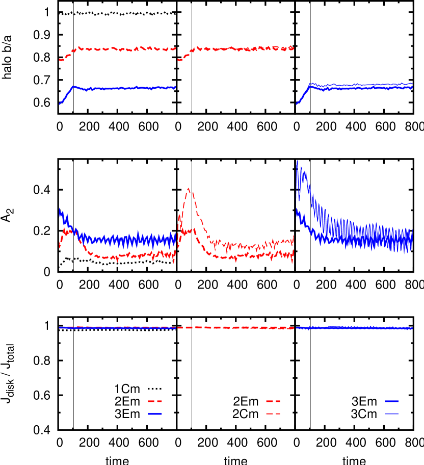
And still we note that, during the period of disc growth, the halo in Fig. 13 does increase. In model 2Em it goes up to about 0.85 and in model 3Em to little more than 0.65 (and slightly more so if the disc is initially circular). This means that introducing a non-bar-forming disc caused very small loss of halo triaxiality and only in the period of disc growth.
Growing the more massive disc causes much greater loss of triaxiality. In Fig. 7, there is also an increase of halo due to disc introduction, but it is much larger, specially in the case of the more triaxial halo, where it grows from 0.6 to 0.8. This means that introducing a (massive) bar-forming disc had caused a loss of triaxiality of about 0.2 in model 3E. This is to be compared with a corresponding increase by 0.05 in model 3Em, which has low mass disc. In the models with the standard disc mass there is further loss of halo triaxiality after the disc has reached its full mass. Thus, by the halo is very near circular (), which means that the amount by which the halo shape changed during and after disc growth are comparable. Equivalently in the case of the less triaxial halo 2E, the increases from 0.8 to 0.9 during disc growth and afterwards gets to about 0.95 as well. For the models with lower mass discs we do not witness any further loss of halo triaxiality after the disc has grown and the total change of triaxality is rather small.
To summarise, we can say the models with low mass discs suffer only a small loss of halo triaxiality and that all of it is due to the introduction of the disc. Although these models isolate the effect of the disc introduction, they can not give us much information on the relative effects of the disc and bar for other cases. They are, nevertheless, applicable to galaxies with low surface brightness discs, and argue that such galaxies should not have suffered much loss of halo triaxiality, and that their halo shape should be near what it was from galaxy formation and as due to effects of interactions and mergings.
Before turning to other ways of assessing the relative role of the disc and bar to the loss of halo triaxiality, we will discuss an interesting property observed in one of our models, model 3Cm. Here we see that the , the strength of = 2 non-axisymmetry, shows oscillations. Viewing the evolution of this model, we see that it did not develop a proper bar but has an elliptical distortion in the centre (with some spiral structure) whose shape oscillates periodically. This elliptical distortion rotates and its elongation is more pronounced when it is perpendicular to the halo elongation. The amplitude always peaks when the orientation of the elliptical elongation is perpendicular to the halo elongation. The oval rotates with a period of about 50 time units and even after 30 alignments, its mean strength has not decreased.
The behaviour of these discs is in some respects analogous to that of galaxies with double-bars (also known as nested bars, or nuclear bars), in which there is a primary (outer) bar and a secondary (inner) bar. In our simulations of low-mass discs inside triaxial haloes, the discs don’t develop bars, but the oval distortion in the disc rotates in the presence of an elongated halo potential. Thus the disc ‘oval’ (to avoid calling it a bar) is analogous to a ‘secondary bar’ and the triaxial halo itself is analogous to a ‘primary bar’, with the difference that the triaxial halo does not rotate and its major axis remains aligned with the -axis.
In their theoretical approach to orbits within double bars, Maciejewski & Sparke (2000), and Maciejewski & Athanassoula (2007) find that the loops supporting the inner bar are thicker when the two bars are parallel; and that if the inner bar is a self-consistent bar made of particles trapped around those loops, it should be thinner when the two bars are perpendicular. Debattista & Shen (2007) describe collisionless -body simulations of discs in rigid haloes, which form double bars. In such simulations, the bar strengths oscillate; the secondary bar becomes stronger when the two bars are perpendicular and weaker when they are parallel. Furthermore, the secondary bar rotates faster than average when they are perpendicular; and slower than average when they are parallel. For our analogous situation (which consists essentially of an elliptically distorted disc rotating in an elongated halo potential) we obtain the same correlations, which are also in agreement with the theoretical predictions of loops by Maciejewski & Sparke (2000). This would argue that low surface brightness galaxies whose discs show important oval distortion could be living in haloes which are still substantially non-axisymmetric.
The amplitude is calculated with bidimensional quantities. In order to have some estimate of the vertical shape of the oval, we compute for the disc particles using the inertia tensor, in the same way as we do for halo shapes. The vertical thickness of the disc (in cases 3Em and 3Cm) also oscillates periodically. The oval is vertically thinner when it is perpendicular to the halo elongation; and it is vertically thicker when it is parallel to the halo elongation. It means that the oval’s elongation correlates with its vertical flattening: when the oval is more elongated, it is also more flattened. Apart from oscillating, the mean thickness increases with time.
The haloes in simulations with low-mass discs remain triaxial. In models 3Em and 3Cm, the shape of the overall halo remains quite constant at about , with no significant radial dependence. In the innermost part of the halo (), however, the halo oscillates, but by no more than 2%. These oscillations are very small, but measurable and quite regular. Furthermore, they anti-correlate sharply with the shape of the oval: when the oval is more elongated, the inner halo is less elongated. But this is not reminiscent of a ‘halo bar’, because there is no halo rotation at any radius: these haloes don’t rotate importantly (except for tumbling slowly), which means that the major axis remains in the same direction.
6.2 Suppressing bar formation by imposing disc axisymmetry
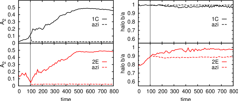
In order to separate the effects of the bar and of the introduction of the disc, we need to analyse simulations in which the disc is standard (i.e. not low mass), but where there is no bar. We try to achieve this artificially, by randomising the azimuthal coordinate of the disc particles in regular time intervals () during the evolution of the system. Artificially forcing the disc to retain axisymmetry throughout the evolution prevents any non-axisymmetric structure from forming. We use the very same discs as in the standard models, which would otherwise form strong bars, and observe the behaviour of their respective haloes in the case where their bar formation is suppressed by axisymmetrisation.
This technique consists in reassigning the coordinate of the disc particles to a random value between 0 and , while keeping their cylindrical radius and their distance from the equatorial plane unaltered at each intervention. This procedure is applied repeatedly during the evolution, from the moment when the disc mass is fully grown, until the end of the simulation and is straightforward in the case of axisymmetric haloes. In our case, however, the potential of the halo is not axisymmetric, so that the particles can find themselves in a region of deeper or shallower potential than before the rotation. Because of that, we re-assign their velocities in such a way as to conserve total energy, while at the same time keeping the angular momentum of each particle unaltered. Tests showed that if the randomisations are discontinued, then bar formation promptly sets in again.
This procedure works well for the spherical halo case because the discs in such haloes are indeed meant to be circular (axisymmetric). In the case of the triaxial haloes, making the disc perfectly axisymmetric causes it to be out of equilibrium with the halo potential. In the case of halo model 2, bar formation was successfully suppressed. However, in the case of halo model 3 it was not possible to apply the randomisations without causing the disc to become severely unstable. Experimentation showed that applying the interventions at different intervals also caused the disc of model 3 to be disrupted by the end of the simulation. Some disc particles end up gaining too much velocity and escape. Since it was not possible to have a permanently circular and stable disc inside a very triaxial halo, we exclude halo 3 from the analysis of this section.
Our purpose here is to evaluate the changes of halo shape in the absence of bar formation. The evolutions of and are shown in Fig. 14, for models 1C and 2E and for the corresponding simulations where the axisymmetrisations described here were applied. The two evolutions before are identical, because no axisymmetrisation was applied while the disc grew, and, for the initially triaxial halo, we witness an increase of the halo from 0.8 to 0.9.
After we start applying the axisymmetrisation, however, the evolutions become different. In the unconstrained simulation, the bar forms and the triaxial halo completely loses its remaining triaxiality and becomes quite axisymmetric by the end of the simulation. In the simulations where the disc is continuously axisymmetrised, however, the bar does not form and there is no further loss of halo triaxiality. So in the absence of bars, the halo of model 2E retains its of 0.9, which otherwise would have gone to 1.
The conclusion is that, in these models, a certain fraction (approximately half) of the loss of halo triaxiality can be attributed to bar formation. It should, however, be remembered that the axisymmetrisation process artificially keeps the model out of equilibrium.
6.3 Hot discs
In axisymmetric haloes, hot discs are known to form oval distortions rather than strong bars (Athanassoula, 1983, 2003, 2005a). We can thus use such discs to investigate whether they are able to completely circularise their haloes, as bar-forming discs do. As initial conditions, we first create circular discs (with Toomre parameter of ), using the method of Rodionov et al. (2009). These discs are meant to be in equilibrium with a spherical halo potential as that of halo 1. They are then made elliptical using the epicyclic approximation, so that their shapes will be in equilibrium with triaxial haloes 2 or 3. In these cases, however, only the positions are altered, while the velocities remain those of a circular disc model, so as to keep the velocity dispersions of the discs. Although this is not strictly correct, such models are nevertheless closer to equilibrium than models of circular discs inside triaxial haloes. During the period of disc mass growth, the velocities gradually adapt to the elliptical potential, while not losing their higher dispersions, which is important to this analysis.
In agreement with what was found in axisymmetric haloes, the models with hot discs can reasonably be said not to have formed bars (Fig. 15), as remains always below 0.1 (except for model 1Chot where it begins to grow a little towards the end of the simulation). The non-zero albeit small values of are merely due to slight oval distortions in the disc. These hot discs lose practically no angular momentum to their haloes (not shown here). The consequence of the lack of bar formation is that again the halo is able to remain triaxial (right panel of Fig. 15). The of halo 2 goes from 0.8 to 0.9 and that of halo 3 goes from 0.6 to 0.8 in the period between and , for both the hot and the normal discs. After that, however, the hot disc loses no further triaxiality, contrary to that of the standard models discussed in Sect. 3.
And so, as was the case also with the haloes of Sect. 6.2, there is no further circularisation besides that which was caused by the disc growth. This is compelling evidence that indeed the bar plays an important role in altering the shape of the halo.
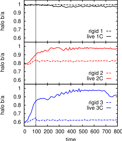
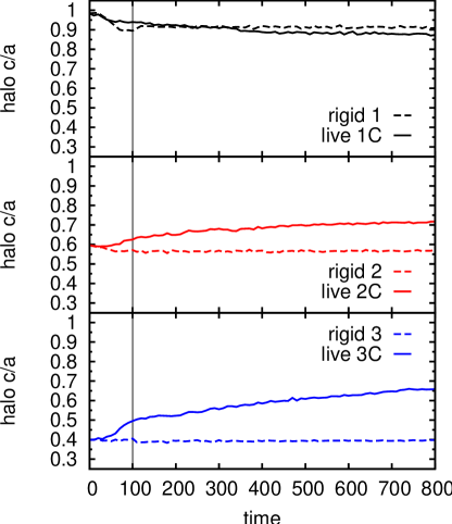
6.4 Rigid discs
Another way of evaluating the effects of bar-forming discs, as opposed to non-bar-forming ones, is to replace the disc particles by an analytic potential. In such a case, the simulation consists only of the usual halo particles, but the disc is represented by a fixed potential, which is rigid and permanently axisymmetric. The halo particles feel their own self gravity and they feel the disc potential that has the same mass and scale lengths as in the simulations with live discs before the disc instability sets in. As in previous cases, we grew the potential gradually into the halo, according to a smooth function of time, between and .
The results in Fig. 16 compare the halo shape evolution of models using live discs and of models with rigid discs. The latter suffer a small amount of circularisation, only in the period of disc growth. The circularisation induced by rigid discs is much smaller than that caused by live discs, and it is in fact smaller even than that caused by low-mass live discs (Sect. 6.1). Once this rigid, circular, disc potential is in place, there is no further change of halo shape. Since there is evidently no bar formation, this again hints in the direction that the presence of the bar has determining effects on the halo shape evolution. For comparison, the models with live discs shown on Fig. 16 are the ones with circular discs, so that the initial conditions are identical in the sense that the shapes and masses of the disc are the same. The rigid disc simulations show us what happens if such circular discs are forced to remain circular and not develop a bar. Simulations with rigid potentials are, however, not realistic because there is no exchange of angular momentum.
7 Vertical shapes
7.1 Halo vertical flattening
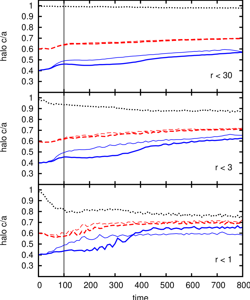
The minor to major axis ratio of the haloes is also affected both by disc growth and by bar formation, but to a lesser degree than the intermediate to major axis ratio . The generally increases, indicating that the halo tends to a less flattened configuration and this, taken together with the its circularisation, shows that the halo tends to become more spherical. Models 1, 2 and 3 start out with axis ratios of 1:1:1, 1:0.8:0.6 and 1:0.6:0.4, respectively and end with oblate shapes of roughly 1:1:0.9, 1:1:0.7 and 1:1:0.6 (as measured in ). The only relevant radial dependence that is introduced in is due to the presence of the disc, which makes the innermost regions somewhat more flattened than the overall shape. In the case of the spherical model, the inner region becomes significantly flatter and this change takes place mostly before . Presumably, due to the growth of disc mass, halo matter is pulled towards the plane and parts of the halo in the immediate surroundings of the disc become flatter than the overall shape. Figure 17 shows the evolution of for the standard models 1C, 2E, 3E as measured within three different radii.

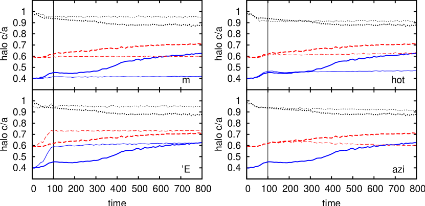
In the simulations using the less massive disc, remains virtually unaffected (Fig. 18), showing not even a slight increase during disc growth. These haloes remain approximately as triaxial as at . The models with a less concentrated halo suffer an increase of only until (the time during which their goes to unity). After that, the does not change anymore and these haloes are oblate by the end of the simulation (Fig. 18).
In the other models where there is no bar formation (hot disc and axisymmetrised disc (Fig. 18)), the increases only slightly until . The comparison of the non-bar-forming models with the standard models shows that in the presence of bar formation the triaxial haloes would have become still less flattened. This indicates that the bar acts not only on the shape of the halo on the equatorial plane, but also affects its vertical flattening; it causes the halo to tend towards sphericity by making it rounder in both directions. In the models with no bar formation, the final shape of the haloes is truly triaxial, being roughly 1:0.9:0.6 for halo 2 and 1:0.8:0.5 for halo 3. Finally, in the spherical model, the halo suffers a small decrease due to disc introduction, in both rigid disc and live disc cases. In the triaxial models, live discs cause a small increase of , but with the rigid discs, there is hardly any change of (Fig. 19).
The final value of depends on the model, and the bar-forming models are the ones in which changes the most. The range of variation of is narrower than that of , but clearly there is a correlation between the amounts of and increase (Fig. 20).
7.2 Formation of boxy/peanut bulges
In simulations with axisymmetric haloes, the discs of strongly barred galaxies show a peanut-shaped structure, when viewed edge-on along the minor axis of the bar. The peanut consists of two prominent humps that swell vertically from the plane of the disc, on both sides. It begins to grow some time after the bar and it becomes significantly stronger after the buckling, when the disc momentarily loses its symmetry with respect to the plane (Combes & Sanders, 1981; Combes et al., 1990; Raha et al., 1991; Athanassoula, 2005b, 2008; Martinez-Valpuesta et al., 2006).
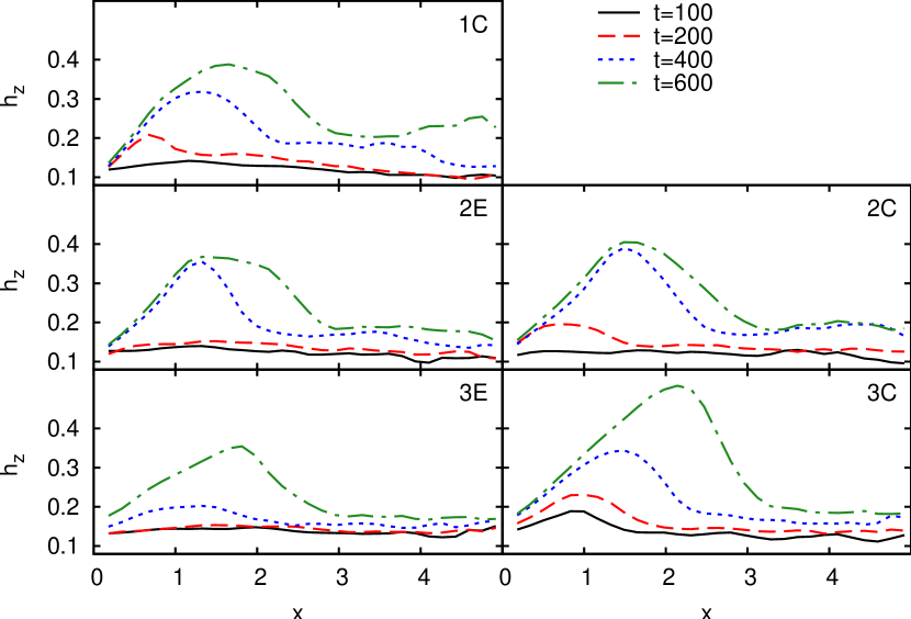
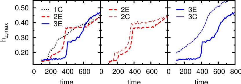
Such structures were also observed in the simulations of Berentzen et al. (2006) and Berentzen & Shlosman (2006), as well as in ours, showing that halo triaxality does not inhibit their formation. We here want to go one step further and check quantitatively the effect of triaxiality on the peanut strength. In order to measure the latter quantity, we follow one of the methods proposed by Athanassoula & Martinez-Valpuesta (2010). We first determine the orientation of the bar and then rotate the disc such that the bar major axis lies in the direction of the -axis. Considering then the disc particles projected on the plane, we measure the dispersion of the coordinates in successive slices of . This dispersion – denoted , to avoid the symbol normally used for velocity dispersions – is an indicator of the thickness of the peanut as a function of . When the peanut forms, reaches a maximum at a position which is near but within the end of the bar, while remaining small in the centre (Fig. 21). As the peanut becomes stronger, the maximum of increases, and the position of the maximum moves further out.
The evolution of peanut strength as a function of time, in simulations with spherical haloes, has been described by Athanassoula (2008). Fig. 22 shows the as a function of time, for different models. We find that in the triaxial models, the formation of the peanut is delayed with respect to the spherical case. Furthermore, for any given halo triaxiality, the C model forms the peanut sooner than the corresponding E model. This is consistent with the fact that the peanut strength is related to the bar strength (Athanassoula & Martinez-Valpuesta, 2010). Since the C models tend to develop stronger bars slightly earlier than the E models, it is expected that they would also grow a strong peanut earlier.
We also measure the skewness of the distribution of vertical coordinates, with respect to , which is a measure of departures from vertical symmetry: high values of correspond to a buckling of the disc. Each sharp increase of the peanut strength coincides with a buckling episode (not shown here). The time of the first buckling increases with the triaxiality of the model. And a C model buckles before the corresponding E model.
8 Kinematics of the disc-like halo particles
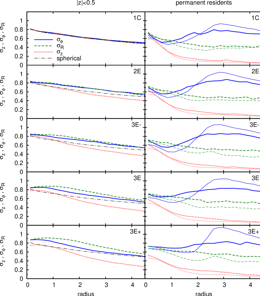
Athanassoula (2007) showed that in strongly barred galaxies, the inner parts of the halo display some mean rotation in the same sense as the disc rotation. This is more important for particles nearer to the equatorial plane and decreases with increasing distance from it, but is always much smaller than the disc rotation. Here we extend this analysis to triaxial haloes and point out some kinematic properties that depend on the initial triaxiality of the haloes.
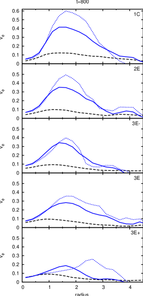
If we select halo particles in a region around the equatorial plane () and measure their tangential velocities at a given time () we already notice that there is some rotation, with peak velocities of about . This definition, however, may include particles which happened to be passing by the equatorial region a , but that are not permanently staying close to it. We, therefore, use two alternative definitions to select these disc-like halo particles: we select the particles that are within at , but that have remained inside this cylinder during (definition 1) or during (definition 2). The first definition already removes many of the particles that were not truly rotating, but definition 2 is even more strict.
The radial profiles of tangential velocities are shown in Fig. 23, for particles simply within at and also for the two other definitions. Note that the tangential velocities are significantly higher when the more strict requirements are applied to define the region of disc-like particles; they range from to 0.6, depending on the model and the definition. The spherical halo shows more rotation than the triaxial ones and indeed the peak tangential velocities decrease with increasing triaxiality. More precisely, it should be stated that the tangential velocity depends on the initial triaxiality of the haloes, because by , these five haloes have approximately the same shapes. And yet their kinematics at that time still depend systematically on the initial shape.
The peak tangential velocities of the five models are shown in the upper panel of Fig. 24. In models whose halo was initially more triaxial, there is less rotation. The lower panel of Fig. 24 shows the radii at which the tangential velocities peak.
The velocity dispersions of the spherical halo are isotropic. The initially triaxial haloes retain an anisotropy, even if by they also have become spherical. The left panel of Fig. 25 shows the radial profiles of the tangential, radial and vertical velocity dispersions for the region of the five haloes. The more triaxial haloes have systematically larger radial dispersions and systematically smaller vertical dispersions (the centre excluded). Such feature one would expect to be due to construction of the triaxial haloes, but they are still present at when all haloes have become roughly spherical. Additionally, it can be noticed that the departures from isotropy increase with initial triaxiality of the model. Again we note that although such anisotropy in the velocity dispersions would be obvious in the initial conditions, it is not evident that it would be retained after the haloes have been circularised and have all reached roughly the same shapes. In the right panel of Fig. 25, the velocity dispersions are shown for the two definitions of the region with disc-like kinematics. In this case, as one would expect for particles that are rotating, the vertical velocities are much smaller and the tangential velocities are much higher than the isotropic velocity dispersions of the spherical case (and slightly more so with definition 2 than with definition 1). With these two definitions, there is no systematic dependence of anisotropy on initial shape (except perhaps in the innermost region, where the spherical halo is more isotropic). But generally, using definitions 1 and 2, the disc-like halo particles show the same regime of rotation for all five models, with the anisotropy peaking at about . Note also that the difference between the results from definitions 1 and 2 increases with increasing initial triaxiality. If the entire halo is taken in account, the velocity dispersions are similar to those of the left panel of Fig. 25.

In order to quantify the anisotropy, we use an anisotropy parameter defined as:
| (16) |
In the case of isotropy, would be 0.5. The value of , calculated from the whole halo, increases with increasing initial triaxiality, which means that the radial motions are correspondingly more important, even at (upper panel of Fig. 26). If only particles within are taken into account, the anisotropy is similar (upper panel of Fig. 26). When using the entire halo or the particles, does not have much radial dependence and does not show important changes with time. The lower panel of Fig. 26 shows the anisotropy for the disc-like halo particles using definitions 1 (solid symbols) and 2 (open symbols). With these definitions and when the anisotropy is measured at (circles), there is some isotropy in the very centre, since there is close to 0.5. When is measured at its peaks (), the anisotropy is larger and shows more important tangential motions (note that the two panels have very different scales). With the more strict definition 2, the anisotropy is even higher. But with either definition and at any radii, there is not a significant dependence of anisotropy (of the disc-like halo particles) with halo model.
9 Summary and conclusions
Cosmological -body simulations have shown that dark matter haloes of galaxies should be triaxial, at least in cases where there are no baryons (Allgood et al., 2006). This can be the result of asymmetric mergings, or of a radial orbit instability (Bellovary et al., 2008), coupled to tidal effects from other galaxies or from groups and clusters. The resulting prolate halo has very little or no figure rotation.
The aim of this paper was to investigate how such a halo will influence bar formation and, more generally, how it will influence the secular evolution of disc galaxies. Our combined disc and halo initial conditions were built so as to be as near equilibrium as possible, with discs which are initially elliptical. We have, nevertheless, also considered initially circular discs, to test what the effect of such less realistic initial conditions would be.
The growth and evolution of such discs drive the haloes rapidly towards axisymmetry, except for the innermost parts, where the final shape of the halo is elongated. This latter effect is independent of the initial halo triaxiality and is found also in initially circular haloes (e.g. Athanassoula, 2005a, 2007; Colín et al., 2006). It is linked to the angular momentum exchange within the galaxy and the formation of a ‘halo bar’, which is shorter and less elongated than the disc bar, but rotates with the same pattern speed.
This innermost prolate elongation put aside, the remaining halo tends towards axisymmetry even for models with considerable initial triaxiality, and this from the moment the disc starts growing. One can distinguish two different axisymmetrisation phases. Initially, while the disc grows, this trend towards halo axisymmetry is quite rapid. The second phase depends on whether or not a bar is formed: in the presence of a bar, the circularisation continues.
The disc shape also changes with time. Initially it is elongated, its ellipticity depending on that of the halo. Thus the is non-zero at , although there is no bar. It decreases with time and reaches a minimum around the time that the disc has reached its maximum mass. After that, the bar starts forming and induces a further increase of halo axisymmetry. In our models, bar formation takes place in the presence of haloes that are still considerably triaxial, even though the triaxiality is later erased. In the more triaxial cases, bar formation is somewhat delayed, but the subsequent evolution of the bar proceeds in a manner similar to the spherical halo case. We have also presented triaxial models that do not develop bars at all; but in such cases, the equivalent spherical ones do not either. The general agreement of our results with previous studies is in the sense that a truly triaxial halo cannot coexist with a strong bar for very long: one of these non-axisymmetries must give way. We have presented simulations in which the bar prevails and the halo triaxiality yields. This argues that in situations where the parameters are such that a bar is known to form in the spherical case, it would also form in the (initially) triaxial cases, further erasing the triaxiality as it does.

Using circular discs, instead of very near-equilibrium elliptical ones, may give rise to quite different evolutions, particularly if the triaxiality of the halo is important. In the case of a very triaxial halo containing a circular disc, the initially increases very abruptly to reach a strong peak and then decays. That was the only simulation in which halo triaxiality damped bar formation, but we stress that this is only when a circular disc was used. In that very triaxial halo, a circular disc is even further from equilibrium than in the less triaxial ones. There are other situations in which grows very abruptly in the very beginning and then decays without forming a bar, and this only happens if we use circular discs as initial conditions. For instance, in the case of low mass discs, the initial increase is due to the circular disc becoming excessively distorted. After the peak, the remaining non-zero is due to a mild oval distortion in the centre of the disc (and also some vague spiral structure), but none of this amounts to actual bar formation (furthermore, there is no exchange of angular momentum between disc and halo).
Such behaviour of might be analogous to those of Berentzen et al. (2006), who also have initially circular discs and find that the bars in their live triaxial haloes dissolve after a few Gyr (except in the case of their more cuspy halo, which does not retain its triaxiality). Similarly, Berentzen & Shlosman (2006), also with initially circular discs, find that bar formation is damped by the triaxiality of the halo. In their models, strong bars form in discs that have erased the halo prolateness almost completely.
In all our models, as in previously run models with initially spherical haloes, bar formation is always necessarily accompanied by angular momentum exchange; more specifically, angular momentum is transferred from the disc to the halo. In the beginning of the simulations, practically all the angular momentum is in the disc. In all models where there is bar formation, the disc-to-total ratio of angular momentum decreases steadily. Further properties of the angular momentum exchange are similar to those found in spherical haloes; e.g. it is related to the bar strength; strong bars causing more transfer from disc to halo. Also, in haloes with large core, the bars are weaker and the angular momentum lost by the disc is correspondingly small. There are simulations where the is non-zero due to oval distortions of the disc which, however, do not qualify as real bars. In such cases, there is very little, if any, angular momentum exchange between disc and halo. We also find differences in angular momentum transfer depending on whether we use circular or elliptical discs as initial conditions. The initially circular discs become excessively elongated during the very short phase of disc growth and they thus develop strong bars faster then the equivalent model with an elliptical disc. These discs, that host stronger bars, lose angular momentum faster. The other quantity that is also closely related to angular momentum transfer and bar strength is the shape of the halo: a stronger bar causes the halo to become axisymmetric faster.
Our standard models have haloes with a small core, of the type called MH in Athanassoula & Misiriotis (2002). Since the core radius is an essential feature in determining the evolution of the galaxy (Athanassoula & Misiriotis, 2002; Athanassoula, 2003), we also ran simulations with large cores, i.e. of the MD type. Here the effect of the disc is even stronger. In all models, by the time the disc was fully grown, the halo has already become nearly axisymmetric, so that any further evolution follows closely that of the MD models of Athanassoula & Misiriotis (2002), namely, compared to MH models, the bar is less strong and there is less angular momentum exchange between the disc and the halo.
We also presented models in which the growth time of the disc was either much smaller, or much bigger than that of the standard models. We found that this does not affect much the results, limiting itself mostly to a temporal shift of the evolution, backwards or forwards in time, respectively. This is in good agreement with similar tests made by Berentzen & Shlosman (2006), albeit with different models.
A crucial question in this context is how much of the loss of the halo triaxiality is due to the introduction of the disc and how much to the formation of the halo. In the case of MD discs, i.e. of discs which are heavy relative to the halo in the inner parts of the galaxy, we saw that by the time the disc has reached its full mass, the halo has become nearly spherical. It is thus reasonable to expect that low mass discs would have a smaller effect on the halo shape, as already found in the simulations of Berentzen & Shlosman (2006). We repeated such simulations here, but with initially elliptical discs. In these cases, our disc has sufficiently low mass so that very little angular momentum can be emitted from its inner regions. Thus although the halo was ready to receive angular momentum, not much exchange was possible for lack of sufficient emitters. As a result, the bar was exceedingly weak, as in the very low mass discs of Athanassoula (2003), and so brought no effect on the halo triaxiality. Thus in these cases the slight decrease of the halo ellipticity when the disc is introduced, is not followed by further decrease caused by the bar. We point out that our corresponding spherical halo model with low mass disc does not develop a bar either, showing that it was not the triaxiality of the other models that was responsible for inhibiting bar formation. In fact, in none of our sets of models with initially near-equilibrium discs, do we find cases where a bar develops in the spherical halo, while failing to do so in the equivalent triaxial ones. Such models, with discs of low mass relative to the halo, give us useful information on galaxies with low surface brightness discs, and argue that such galaxies should not have suffered much loss of halo triaxiality, and that their halo shape should be near what it was from galaxy formation and as due to effects of interactions and mergings.
We made further simulations to find what fraction of the triaxiality loss can be attributed to the disc introduction and what to the formation and evolution of the bar. For this we ran models where the disc was kept artificially axisymmetric, models where the disc was very hot (so that bar grew very slowly and was more of an oval than a strong bar) and models where the disc was rigid. In these three cases (as well as in the low mass case), the simulations were designed so as not to form bars. In all cases where there is no bar, the halo is able to remain triaxial until the end of the simulation. Any circularisation that takes place is restricted to the period of disc growth. This circularisation is particularly small if the disc mass is small or if the disc is rigid. The rigid discs – where the potential of a (permanently circular) disc is represented by an analytic potential instead of live particles – are the ones that cause the smallest effects on their haloes, suggesting that it is not merely the presence of disc mass that alters the halo shape, but also the active response of the disc orbits that oppose the halo elongation.
We find that the vertical shape of the triaxial haloes is also affected both by disc growth and by bar formation, in the sense that haloes become less flattened with time. These changes are, however, always small compared to the changes in the equatorial shape. Nevertheless, in cases where the increase is more pronounced, that of is important also. The general evolution of vertical shapes is thus analogous to that of the halo shape on the plane of the disc: disc introduction causes some degree of change and the subsequent formation of a bar determines whether or not there will be further loss of flattening. But even in models where a strong bar forms (and the halo is thus completely axisymmetrised), the vertical flattening remains considerable, meaning that the haloes have become approximately oblate by the end of the simulation.
As the bar forms, the vertical structure of the disc is also affected. As with previous simulations of axisymmetric galaxies, the discs in the triaxial models also undergo buckling episodes and peanut formation. In our initially triaxial models that form strong bars, the first buckling of the disc occurs later than in the spherical case. Consequently, peanut formation is delayed in the triaxial models. The models with initially circular discs develop stronger peanuts before the corresponding models with elliptical discs. All this is in agreement with the fact that peanut strength is related to bar strength (Athanassoula & Martinez-Valpuesta, 2010), and the fact that bars grow faster in initially circular discs.
The spherical halo particles in a layer near the equatorial plane acquire during the evolution some rotation in the same sense as the disc rotation, as in Athanassoula (2007). We extended that analysis to triaxial haloes. We select halo particles that are permanently in the vicinity of the plane; by analysing their radial profiles of tangential velocities, we find that these ‘disc-like’ halo particles show considerable rotation, with velocities of the order of half of that of the disc particles. Such rotation is present as well in the triaxial models and the peak tangential velocities depend systematically on the initial triaxiality of the model. There is more rotation in the spherical halo than in the triaxial ones, even though their shapes are roughly the same by the end of the simulation. Apart from the rotation, there is another kinematic feature which is dependent on the initial triaxiality: the anisotropy of the velocity dispersions. If we consider the entire haloes, we see that the in spherical one the velocities are isotropic, but the initially triaxial models retain their anisotropy even after their shapes have become approximately spherical. We find that the velocity anisotropy at the end of the simulation depends systematically on the initial triaxiality.
To summarise, we have presented simulations of bar formation in triaxial haloes and showed that the haloes become more axisymmetric due to two separate factors: disc growth and bar formation. Typically half the circularisation can be attributed to the introduction of the disc and the other half to the formation of a strong bar. Halo vertical flattening is also affected, but to a much lesser degree, meaning that haloes become roughly oblate by the end of the simulation. This is the first study of bar formation and disc bar evolution in which live elliptical discs within live triaxial haloes were employed as the initial conditions for -body simulations. Elliptical discs have the advantage of being closer to equilibrium and of not responding to the presence of the aspherical halo potential by becoming excessively and unphysically distorted, as circular discs tend to do. We have also analysed the kinematics of the halo and pointed out that even after the haloes lose their triaxiality, they are able to retain the anisotropy of their velocity dispersions. We also note that the disc-like particles of the halo rotate less in the haloes that were initially triaxial.
Interesting issues remain to be explored. Simulations such as these, in which all components are live, can be used to study in detail the orbital structure, not only during the period of disc growth, but also during the period of bar formation. Another interesting issue is the effect of gas on the dynamics of these systems. Simulations analogous to the ones we have presented, but including also a gas component are currently under way and will be the subject of a forthcoming paper.
Acknowledgements
We wish to thank the referee for his fast reply and careful reading. REGM acknowledges support from the Brazilian agencies FAPESP (05/04005-0) and CAPES (3981/07-0), and from the French Ministry of Foreign and European Affairs (bourse Eiffel). This work was partly supported by grant ANR-06-BLAN-0172.
References
- Allgood et al. (2006) Allgood B., Flores R. A., Primack J. R., Kravtsov A. V., Wechsler R. H., Faltenbacher A., Bullock J. S., 2006, MNRAS, 367, 1781
- Athanassoula (1983) Athanassoula E., ed. 1983, in Internal Kinematics and Dynamics of Galaxies, IAU Symp. 100, Dordrecht: Reidel, 432pp
- Athanassoula (2002) Athanassoula E., 2002, ApJL, 569, L83
- Athanassoula (2003) Athanassoula E., 2003, MNRAS, 341, 1179
- Athanassoula (2005a) Athanassoula E., 2005a, Celestial Mechanics and Dynamical Astronomy, 91, 9
- Athanassoula (2005b) Athanassoula E., 2005b, MNRAS, 358, 1477
- Athanassoula (2007) Athanassoula E., 2007, MNRAS, 377, 1569
- Athanassoula (2008) Athanassoula E., 2008, in Formation and Evolution of Galaxy Bulges, IAU Symp. 245, eds M. Bureau, E. Athanassoula and B. Barbuy, Cambridge University Press, 93
- Athanassoula & Martinez-Valpuesta (2010) Athanassoula E., Martinez-Valpuesta I., 2010, MNRAS, in press
- Athanassoula & Misiriotis (2002) Athanassoula E., Misiriotis A., 2002, MNRAS, 330, 35
- Athanassoula & Sellwood (1986) Athanassoula E., Sellwood J. A., 1986, MNRAS, 221, 213
- Bailin et al. (2007) Bailin J., Simon J. D., Bolatto A. D., Gibson B. K., Power C., 2007, ApJ, 667, 191
- Bailin & Steinmetz (2004) Bailin J., Steinmetz M., 2004, ApJ, 616, 27
- Bailin & Steinmetz (2005) Bailin J., Steinmetz M., 2005, ApJ, 627, 647
- Bellovary et al. (2008) Bellovary J. M., Dalcanton J. J., Babul A., Quinn T. R., Maas R. W., Austin C. G., Williams L. L. R., Barnes E. I., 2008, ApJ, 685, 739
- Berentzen & Shlosman (2006) Berentzen I., Shlosman I., 2006, ApJ, 648, 807
- Berentzen et al. (2006) Berentzen I., Shlosman I., Jogee S., 2006, ApJ, 637, 582
- Binney & Tremaine (1987) Binney J., Tremaine S., 1987, Galactic Dynamics. Princeton University Press
- Cole & Lacey (1996) Cole S., Lacey C., 1996, MNRAS, 281, 716
- Colín et al. (2006) Colín P., Valenzuela O., Klypin A., 2006, ApJ, 644, 687
- Combes et al. (1990) Combes F., Debbasch F., Friedli D., Pfenniger D., 1990, A&A, 233, 82
- Combes & Sanders (1981) Combes F., Sanders R. H., 1981, A&A, 96, 164
- Curir et al. (2006) Curir A., Mazzei P., Murante G., 2006, A&A, 447, 453
- Debattista et al. (2008) Debattista V. P., Moore B., Quinn T., Kazantzidis S., Maas R., Mayer L., Read J., Stadel J., 2008, ApJ, 681, 1076
- Debattista & Sellwood (2000) Debattista V. P., Sellwood J. A., 2000, ApJ, 543, 704
- Debattista & Shen (2007) Debattista V. P., Shen J., 2007, ApJL, 654, L127
- Dehnen (2000) Dehnen W., 2000, ApJL, 536, L39
- Dehnen (2002) Dehnen W., 2002, Journal of Computational Physics, 179, 27
- Dubinski & Carlberg (1991) Dubinski J., Carlberg R. G., 1991, ApJ, 378, 496
- Fasano et al. (1993) Fasano G., Amico P., Bertola F., Vio R., Zeilinger W. W., 1993, MNRAS, 262, 109
- Franx et al. (1994) Franx M., van Gorkom J. H., de Zeeuw T., 1994, ApJ, 436, 642
- Frenk et al. (1988) Frenk C. S., White S. D. M., Davis M., Efstathiou G., 1988, ApJ, 327, 507
- Gadotti & de Souza (2003) Gadotti D. A., de Souza R. E., 2003, ApJL, 583, L75
- Gerhard & Vietri (1986) Gerhard O. E., Vietri M., 1986, MNRAS, 223, 377
- Hayashi et al. (2007) Hayashi E., Navarro J. F., Springel V., 2007, MNRAS, 377, 50
- Heller et al. (2007) Heller C. H., Shlosman I., Athanassoula E., 2007, ApJ, 671, 226
- Hernquist (1993) Hernquist L., 1993, ApJS, 86, 389
- Holley-Bockelmann et al. (2001) Holley-Bockelmann K., Mihos J. C., Sigurdsson S., Hernquist L., 2001, ApJ, 549, 862
- Jing & Suto (2002) Jing Y. P., Suto Y., 2002, ApJ, 574, 538
- Jog (2000) Jog C. J., 2000, ApJ, 542, 216
- Kazantzidis et al. (2004) Kazantzidis S., Kravtsov A. V., Zentner A. R., Allgood B., Nagai D., Moore B., 2004, ApJL, 611, L73
- Lambas et al. (1992) Lambas D. G., Maddox S. J., Loveday J., 1992, MNRAS, 258, 404
- Maciejewski & Athanassoula (2007) Maciejewski W., Athanassoula E., 2007, MNRAS, 380, 999
- Maciejewski & Sparke (2000) Maciejewski W., Sparke L. S., 2000, MNRAS, 313, 745
- Martinez-Valpuesta et al. (2006) Martinez-Valpuesta I., Shlosman I., Heller C., 2006, ApJ, 637, 214
- Novak et al. (2006) Novak G. S., Cox T. J., Primack J. R., Jonsson P., Dekel A., 2006, ApJL, 646, L9
- O’Neill & Dubinski (2003) O’Neill J. K., Dubinski J., 2003, MNRAS, 346, 251
- Raha et al. (1991) Raha N., Sellwood J. A., James R. A., Kahn F. D., 1991, Nature, 352, 411
- Rix & Zaritsky (1995) Rix H.-W., Zaritsky D., 1995, ApJ, 447, 82
- Rodionov et al. (2009) Rodionov S. A., Athanassoula E., Sotnikova N. Y., 2009, MNRAS, 392, 904
- Ryden (2004) Ryden B. S., 2004, ApJ, 601, 214
- Ryden (2006) Ryden B. S., 2006, ApJ, 641, 773
- Sellwood (1980) Sellwood J. A., 1980, A&A, 89, 296
- Tissera et al. (2009) Tissera P. B., White S. D. M., Pedrosa S., Scannapieco C., 2009, arXiv:0911.2316
- Trachternach et al. (2008) Trachternach C., de Blok W. J. G., Walter F., Brinks E., Kennicutt R. C., 2008, AJ, 136, 2720
- Valluri et al. (2009) Valluri M., Debattista V. P., Quinn T., Moore B., 2009, arXiv:0906.4784
- Villa-Vargas et al. (2009) Villa-Vargas J., Shlosman I., Heller C., 2009, ApJ, 707, 218
- Warren et al. (1992) Warren M. S., Quinn P. J., Salmon J. K., Zurek W. H., 1992, ApJ, 399, 405
- Widrow (2008) Widrow L. M., 2008, ApJ, 679, 1232