Relay-Assisted Partial Packet Recovery with IDMA Method in CDMA Wireless Network
Abstract
Automatic Repeat Request (ARQ) is an effective technique for reliable transmission of packets in wireless networks. In ARQ, however, only a few erroneous bits in a packet will cause the entire packet to be discarded at the receiver. In this case, it’s wasteful to retransmit the correct bit in the received packet. The partial packet recovery only retransmits the unreliable decoded bits in order to increase the throughput of network. In addition, the cooperative transmission based on Interleave-division multiple-access (IDMA) can obtain diversity gains with multiple relays with different locations for multiple sources simultaneously. By exploring the diversity from the channel between relay and destination, we propose a relay-assisted partial packet recovery in CDMA wireless network to improve the performance of throughput. In the proposed scheme, asynchronous IDMA iterative chip-by-chip multiuser detection is utilized as a method of multiple partial recovery, which can be a complementarity in a current CDMA network. The confidence values’ concept is applied to detect unreliable decoded bits. According to the result of unreliable decoded bits’ position, we use a recursive algorithm based on cost evaluation to decide a feedback strategy. Then the feedback request with minimum cost can be obtained. The simulation results show that the performance of throughput can be significantly improved with our scheme, compared with traditional ARQ scheme. The upper bound with our scheme is provided in our simulation. Moreover, we show how relays’ location affects the performance.
I Introduction
Currently, Direct-Sequence Code Division Multiple Access (DS-CDMA) wireless networks is widely deployed [1], such as in IEEE b. At the link layer of such networks, the Automatic Repeat Request (ARQ) protocol is usually used to ensure the reliable delivery of packets with Cyclic Redundancy Check (CRC) to check whether the received packet has errors. If the error in the received packet is detected by CRC, the erroneous packet is discarded and retransmission is requested by the receiver. There are many possible causes for errors, such as a non-ideal state of channel between the transmitter and receiver, collision of packets in random access networks and so on. To address the packet collision problem, IEEE wireless networks employ Carrier Sense Multiple Access(CSMA) and the Request-To-Send(RTS)/Clear-To-Send(CTS) mechanisms at the MAC layer [1]. However, retransmissions are not completely avoided because erroneous receptions still happen. Therefore, ARQ is employed to guarantee quality of service (QoS). ARQ with a limit on the maximum number of retransmissions, called truncated ARQ, is applied to reduce the delay and buffer size [2]. In truncated ARQ, if a packet still has errors after being retransmitted for the maximum number of times defined, the packet will be discarded and a packet loss is announced. The truncated ARQ can improve the packet error rate (PER), but it cannot achieve throughput gains. This is because more transmission time is required for better PER performance. Moreover, if the channel between source and destination is in a poor state, the performance of throughput cannot be improved with the increases in number of retransmissions.
Recently, a partial packet recovery scheme was proposed to improve the throughput performance in [3]. In the traditional ARQ scheme, the entire packet is retransmitted even though there may be only one error in the packet. The basic idea behind partial packet recovery is to retransmit only the erroneous bits if a received packet cannot pass the CRC. In the partial packet recovery scheme, the receiver knows probably error bits’ position in the received packet with a unreliable decoded bits detection. The threshold method can be applied in the unreliable decoded bits detection. According to the results of unreliable decoded bits detection, the receiver feeds back a request message to the transmitter so that the transmitter is aware of which part of the packets needs retransmission. The size of request message feedback from the receiver to the transmitter is a key issue for the partial packet recovery. When the request message costs too many bits to feed back from the receiver, the throughput will decrease. A feedback strategy based on the cost evaluation is used to solve the feedback request issue.
Cooperative transmission techniques can provide diversity gains through relays in the fading wireless channel [4, 5, 6]. In [7], a cooperative packet recovery scheme is proposed. It requires retransmission of the entire packet, and combines confidence information across multiple copies of a packet from multiple access points which are connected by wired Ethernet. In fact, this is equivalent to a multiple antenna receiver scheme without the assistance of relay. In [8], the truncated cooperative ARQ scheme is proposed to obtain throughput gains by the relay-assisted method, where sources and relays use an orthogonal space-time block code (STBC) to retransmit the entire packets. However, this scheme requires close synchronization of the source and relays for STBC to work, and coordinating different transmitters in the wireless network can be difficult.
To overcome the synchronization challenge, Interleave-division multiple-access (IDMA) has the advantage that it works in an asynchronous cooperative communication network scenario [9]. IDMA provides a good interference cancellation performance. Moreover, the Multi-User Detection (MUD) in IDMA has a linear complexity, implying a lower cost than the MMSE-based MUD which has polynomial complexity in CDMA [10, 11, 12]. In [13], a scenario is described where multiple source-destination pairs are assisted by multiple common relays based on IDMA. The work in [13] shows that IDMA relays at different locations provide different diversity gains for the multiple source-destination pairs.
In this paper, we propose a relay-assisted partial packet recovery scheme. In our scheme, IDMA is applied as a partial packet recovery method. We not only bring diversity gains into the partial packet recovery with relays, but also take advantage of IDMA for recovering multiple erroneous packets. The proposed IDMA partial packet recovery can be used to recover the erroneous packet under the following scenario: a wireless network that is under heavy load may have to handle more than one corrupted packet at the same time slot. An example of this scenario is when CSMA and RTS/CTS fail to avoid the collision between two source packets. If both source packets are intending for the same destination, the receiver at the destination will be required to handle the partial packet recovery for more than one packet at the same time. Hence, more than one packets need to recover at the destination in the partial packet recovery scheme. To recover the multiple erroneous packets, the IDMA MUD may concurrently receive and separate all retransmitted partial packets from multiple relays for multiple source’s packet. In addition, the asynchronous property of iterative chip-by-chip MUD mechanism in our proposed IDMA scheme enables the receiver to extract multiple partial packets of different sizes. Because the size of different retransmitted partial packets may be different in the case of multiple partial packets recovery. The simulation results show that the proposed scheme outperform the traditional ARQ.
This paper is organized as follows: In Section II, we introduce the system model. In Section III, we present the proposed IDMA-based partial packet recovery scheme. Section IV, we show the simulation result. In Section V, we provide a conclusion to this paper.
II System Model
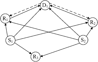
Assume that we have sources, one destination and relay nodes in the wireless communication network. Figure 1 shows the scenario with sources, a destination and relays with different locations. and are the sources, and is the destination. , and are a group of relay candidates to assist in partial packet recovery. The roles of all nodes are fixed in the network, i.e., relay nodes will not act as a source node at different time slot. Each node works in the half-duplex mode and BPSK is used for the modulation. The relay-assisted partial packet recovery protocol divides the operation into three time slots. In the first time slot, source nodes transmit their signal to a group of relays and the destination. All transmissions in the first time slot are based on CDMA. This assumes that CSMA and RTS/CTS have not prevented more than one active source to transmit at the same time in the network. In the second time slot, the destination uses CRC to check whether the received packets have errors. If no error is found, the destination broadcast an ACK message to the sources and the group of relays. In the third time slot, after seeing the ACK message, sources will proceed to transmit the next packet in their queues, and relays will erase the packet received during the first time slot and proceed to receive the next packet. On the other hand, if CRC error is detected at destination in the second time slot, the destination broadcasts a feedback request message on the feedback channel. This request message includes the information describing which part of the packet needs retransmission. The CRC at relays and destination is assumed to be perfect error detection. Assume that the feed back channel is error-free. The best relay for each source is assumed to be known in this paper, and the relay has no error in decoding the source’s packet, as achieved by the CRC at its receiver.Hence, relays assist sources to recovering erroneous packets in our system model. Note that the relay is equipped with IDMA’s transmitter. In the third time slot, the relay responses the request, the received signal at the destination is given by:
| (1) |
where let denote the length of partial packet transmitted by -th relay, with . denotes the unit power signal generated by the IDMA transmitter at relay , denote the delay variables for different partial packets. is the channel gain from relay to destination. is the transmit power at relay . denotes the noise level at destination. follows a Gaussian distribution with variance .
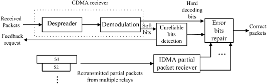
Figure 2 shows the structure of the CDMA receiver at the destination which is equipped with an IDMA partial recovery module. In Figure 2, the hard decoding bits and the soft bits are both outputs from the demodulation unit. The soft bits can provide information about the confidence level of hard decoding. The unreliable bits detection block in Figure 2 uses the confidence information to detect unreliable bits in the received packet. It then feeds back a retransmission request for these unreliable bits. Multiple partial packets retransmitted by multiple relays are received by the IDMA partial packet receiver, Which utilizes the chip-by-chip multiuser detection to separate the different sizes of partial packets, denoted by and blocks. The received partial packets will be input to the error bits repair block, where the unreliable bits will be replaced by the retransmitted bits and the multiple partial packets recovery is finally completed.
III Partial packet recovery with IDMA method
The partial packet recovery with IDMA method is activated only if the received packet is detected to have the error in CRC. The improvement of throughput brought by partial packet recovery is due to save the time to retransmit the correct bits. Hence, we need to know which part of bits are unreliable (“bad”), so the unreliable bit detection unit is used for this purpose. Here, the concept of soft bits and confidence values is applied to detect error bits. The confidence values measure how much reliable of decoding. The error bits detection is based on threshold method. If the confidence value of a bit is larger than the preset value of threshold, the destination recognizes a decoded bit as reliable. Otherwise, the destination starts to determine a feedback request strategy. The feedback request strategy is designed for minimizing the cost of retransmission, and consequently decides a list of retransmitted bit’s indices in a packet.
Then, this list is broadcasted on the feedback channel. According to this list, the multiple best relays for multiple source’s packets transmit the multiple partial packet with IDMA. In the case of multiple packets recovery, the lists correspond to multiple packets feedback sequentially. After receiving these multiple partial packets, the destination repairs the “bad” bits in multiple packet to recover correct packets.
III-A Soft bits and confidence values
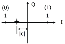
The concept of soft bits in partial packet recovery is similar to the soft decoding [3, 7]. A soft bit is defined as a real number in [-1,1] corresponding to a binary bit. The absolute value of the soft bit indicates the confidence of decoding, as shown in Figure 3. In the soft decoding case, soft bits from demodulation are forwarded to the soft decoding unit, and these soft bits will be discarded after the decoding. In partial packet recovery, the soft bits are forwarded up to the link layer for ARQ . The confidence value is a metric which measures the reliability in the correctness of the decoded bit. Assume that the received signal is modeled by:
| (2) |
where is the CDMA transmitted signal, denotes the thermal noise, is the channel coefficient. Let the transmitted BPSK symbol represented by , is the data length. is spread by a spreading sequence v with the length of . The spreading process is given as: . Let denote the output from demodulation without hard decisions. For simplicity, we take the first BPSK symbol as an example to illustrate the concept. After the despreading and demodulation in Figure 2, the first soft bit is given by , where the numerator is the summation over all chips related to the first BPSK symbol, the denominator is for normalization. Figure 3 shows the soft bit , denoted by the star point, in the constellation. In fact, the Euclidean distance between the and the origin is the amount of confidence values. For example, the confidence value of the first bit can be obtained by: .
III-B Unreliable decoded bits detection
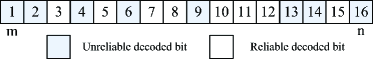
To implement the idea of partial packet recovery, probably error bits in a received packet should be estimated at destination so that this part of error bits can be requested to retransmit. The destination can utilize the confidence value provided by physical layer to make decisions on which bits is probably error and need to retransmit. If the absolute value of soft bits is smaller, the confidence about decoding for correctness is less. That is, the high probability of error decoding is with the bits which having smaller absolute value of soft bits. The threshold method in [3] is adopted to detect unreliable decoded bits. Instead of Hamming distance in [3], we measure the soft bit and confidence value with Euclidian distance. Let denotes a preset threshold of confidence value. If a bit with the confidence value , , this bit is labeled as a good bit. Otherwise, this bit is labeled as a bad (unreliable) bit, retransmission of this bit is requested. As an example, a -bit packet with unreliable decoded bits detection is illustrated in Figure 4. The confidence value of each bit in the packet is obtained by the soft bit, which is outputted from the demodulation in the physical layer. The unreliable decoded bits detection can be implemented in the link layer, and the information of confidence is conveyed from physical layer to link layer. Unreliable decoded bits are detected by comparing confidence values with the threshold. In Figure 4, the indexes of decoded bits with confidence value lower than the threshold are and . Only these unreliable bits are requested to retransmit.
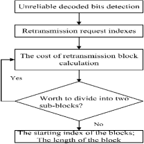
III-C Recursive algorithm of feedback request strategy
Beyond simple ACK/NACK ARQ, partial packet recovery requires the feedback of the indexes of the unreliable bits in a packet. If this information is large, the cost of the feedback request is large and the throughput performance is degraded. Hence, the feedback request strategy needs to be designed carefully. We adopt the cost-based method, which is proposed in [3], to design a recursive algorithm. The flow chart of our algorithm is shown in Figure 5. First, the unreliable bits in a decoded packet are detected and indexes of the unreliable bits are obtained. Let the set denote the index set of the unreliable bits. If the information in the index set is larger than the retransmission of an entire block which contains both reliable bits and unreliable bits, the retransmission of entire block is preferred. Let and represent the starting index and the ending index in a retransmit block in Figure 4, respectively. Assume a packet has data bits. The cost of retransmitting the entire block which contains all bits from the -th position to the -th position in a packet is given by:
| (3) |
where the starting index of the block needs bits to describe, and the length of block also needs bits in the feedback request. The number of retransmitted bits is . So the total cost is bits. Similarly, the cost of dividing the entire block into two sub-block is obtained by:
| (4) |
where and are the new starting index and new ending index for the division from a block into two sub-blocks. We use the following criterion to select the and in a block:
| (5) |
where indicates that there are (--1) reliable bits between the -th and the -th unreliable bits. To compare two options in (3) and (4) , we need to select and for minimizing the cost in (4). For the option in (4), reliable bits are not retransmitted, as the entire block, which is from the -th to -th bits, is divided into two sub-blocks, which include the -th to -th bits, and the -th to -th bits, respectively. In (5), the cost can be minimized by maximizing . In our recursive algorithm, a decision whether it is worth to divide a block into two sub-blocks is made according to this cost. The cost is evaluated between the two options by:,where we select the option with the smaller cost. Our recursive algorithm keeps running on all resulted blocks after each recursion. Once the cost does not change between iterations, the recursive algorithm stops, and the final feedback request strategy is decided. The starting index and length of each retransmission block is broadcasted in the feedback channel.
III-D IDMA in partial packet recovery
The retransmission request is broadcasted in the feedback channel. This request can be received by the sources and relays. To response the request, multiple relays apply IDMA method to transmit multiple partial packets to the destination for the recovery. If no relay responses the request, the source perform the entire packet retransmission. In Figure 1, the IDMA partial packet receiver applies asynchronous iterative chip-by-chip MUD to decode the multiple partial packets from multiple relays. The Log Likelihood Ratio (LLR) output from asynchronous iterative chip-by-chip MUD is given as follows:
| (6) |
where
| (7) |
| (8) |
| (9) |
and
| (10) |
(6) detects the received signal from the -th relay in multiple packets signal . (7) and (8) are respectively the mean and variance of the interference for the received signal from the -th relay. (9) and (10) are the mean and variance of the received signal from -th relay. IDMA MUD estimates the statistic of the interference through the iterations. The update rule for the estimation in each iteration for the -th partial packet is given by:
| (13) |
| (16) |
where denotes the a priori information provided by the despreader for MUD in IDMA receiver. After decoding the partial packet with IDMA, the decoded bits in the partial packet is used to replace the unreliable bits in the error bits repair block in Figure 2. Finally, repaired bits and reliable bits constitute a recovered packet. If the recovered packet is still in error, the partial packet recovery with IDMA method is activated again. Similar to truncated ARQ, the request for partial retransmission may keep running until the recovered packet passes the CRC check or until the maximum number of retransmission is reached.
IV Simulation
| SNR (dB) | -5 | 0 | 5 | 10 | 15 | 20 | 25 |
|---|---|---|---|---|---|---|---|
We simulate a wireless network, which consists of two sources, one destination, and three relay candidates over flat Rayleigh fading channels. The length of data packet is bits. The number of iterations at the IDMA MUD receiver are . The path loss exponent is set to be . The distance between two sources and a destination is fixed at meters. Let denote the total number of correctly received bits in the whole transmission, the total number of transmit bits by sources and relays , and the total number of bits for feedback request in partial packet recovery. For the performance’s comparison, we define the throughput with ACK/NACK ARQ scheme as:. Here, the bits used for ACK/NACK are ignored. The throughput with relay-assisted IDMA partial retransmission is defined as:, where includes all information describing which part of bits requested to retransmit. This is decided by feedback request strategy. There are two types of curves provided in our simulation: one is the upper bound of throughput for the proposed scheme; the other is the throughput, where the threshold method in Section III-B is adopted for unreliable decoded bits detection. Meanwhile, we compare the performance of throughput with the proposed scheme under different maximum times of retransmission and different location settings. Let denote the maximum number of retransmission, and the distance between relays and destination. The upper bound curves assume that the unreliable decoded bits are perfectly detected so that the destination has a perfect knowledge of erroneous bits’ position in the packet. In the simulation, for the unreliable bit detection threshold, we select the thresholds of confidence values listed in table I under different SNR conditions in the simulation. All values of threshold in table I are obtained by accumulative simulations. In addition, the two best relays are selected to assist the two sources, respectively. Figure 6 shows the improvement in the throughput with the IDMA relay-assisted partial packet recovery, over the traditional ARQ with entire packet retransmission in CDMA networks.
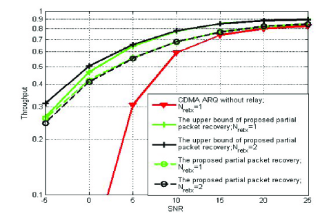
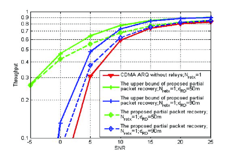
In Figure 6, the two best relays are located in the middle of sources and destination. It has been shown that IDMA relay-assisted partial packet recovery has an advantage over the traditional ARQ entire packet retransmission scheme in CDMA network. Figure 7 illustrates that the location of the best selected relay can affect the performance of IDMA relay-assisted partial packet recovery. Two cases of location setting are simulated for comparison: distance between relays and destination of m, and of m. When the relays are far away from the destination, the performance is degraded because the channels between relays and the destination degrade, and there is a performance loss compared to the performance of the upper bound because there can be errors in the detection of the unreliable bits using the confidence threshold.
V Conclusion
A relay-assisted partial packet recovery scheme using IDMA is proposed in this paper. We use relays to provide diversity gain for retransmitting the partial packet. The transmission of relay-assisted partial packet recovery is activated only when errors are detected in the received packet at the destination. In our scheme, multiple relays at different locations can assist to recover multiple source packets using IDMA. The asynchronous IDMA iterative chip-by-chip multiuser detection is adopted to decode multiple partial packets. Further, we adopt the concept of confidence value to detect the unreliable bits in a packet, and the threshold detection method is introduced. To minimize the feedback request overhead, we design a recursive algorithm based on cost evaluation to determine the retransmission strategy. Simulation results show the throughput upper bound of the proposed scheme, and the performance improvement of the proposed scheme over the traditional ARQ in wireless CDMA networks. In the optimal case, the performance upper bound shows that there is at least a dB gain with our proposed scheme for a given throughput value. For the detection of unreliable bits, the proposed scheme can obtain at least a dB gain under low SNR conditions, without optimization of the threshold setting. To achieve more accurate detection of unreliable bits, more sophisticated detection algorithm will be developed in future work.
References
- [1] ISO/IEC, “Wireless LAN Medium Access Control (MAC) and Physical Layer (PHY) Specifications,” ANSI/IEEE Std 802.11, 1999.
- [2] E. Malkamaki and H. Leib,“Performance of truncated type-II hybrid ARQ schemes with noisy feedback over block fading channels,”IEEE Transactions On Communications, vol. 48, no. 9, pp. 1477 - 1487, Sept. 2000.
- [3] K. Jamieson and H. Balakrishnan, “PPR: Partial packet recovery for wireless networks,” in ACM SIGCOMM, pp. 409-420, Kyoto, Japan, Aug.2007.
- [4] J. N. Laneman, D. N. C. Tse and G. W. Wornell,“Cooperative diversity in wireless networks: Efficient protocols and outage behavior ”, IEEE Transactions On Information Theory, vol. 50, no. 12, pp. 3062 - 3080, Dec. 2003.
- [5] A. Sendonaris, E. Erkip, and B. Aazhang, “User cooperation diversity part I: System description”, IEEE Transactions On Communications, vol. 51, no. 11, pp. 1927 - 1938, Nov. 2003.
- [6] K. J. R. Liu, A. K. Sadek , W. Su, and A. Kwasinski, Cooperative Communications and Networking, Cambridge University Press, Cambridge, UK, 2008.
- [7] G. R. Woo, P. Kheradpour, D. Shen, and D. Katabi, “Beyond the bits: cooperative packet recovery using physical layer information,” in ACM MobiCom’07,pp.147-158, Montréal, Québec, Canada, Sept. 2007.
- [8] L. Dai and K. B. Letaief, “Throughput maximization of Ad-hoc wireless networks using adaptive cooperative diversity and truncated ARQ,” IEEE Transactions On Communications, vol. 56, no. 11, pp. 1907 - 1918, Nov. 2008.
- [9] Z. Fang, L. Li, and Z. Wang,“An interleaver-based asynchronous cooperative diversity scheme for wireless relay networks”, IEEE International Conference on Communications, pp. 4988-4991, Beijing, China, May, 2008.
- [10] L. Ping, L. Liu, K. Y. Wu, and W. K. Leung, “Interleave division multiple access,”IEEE Transactions On Wireless Communications, vol. 5, no. 4, pp. 938 - 947, Apr. 2006.
- [11] L. Liu and L. Ping, “A comparative study on low-cost multiuser detectors”, IEEE International Conference on Communications, pp. 4947-4952, Istanbul, Turkey, Jun. 2006.
- [12] W. K. Leung, L. H. Liu, and L. Ping , “Interleaving-based multiple access and iterative chip-by-chip multiuser detection”, IEICE Transaction On Communications, E86-B (12): 3634-3637, 2003.
- [13] Z. Luo, D. Gurkan, Z. Han, A. K. Wong, and S. Qiu, “Cooperative Communication based on IDMA”, in Proceedings of the 5th International Conference on Wireless Communications, Networking and Mobile Computing, Beijing, China, Sept. 2009.