On leave from]Physical-Technical Institute, Tashkent 100012, Uzbekistan On leave from]Lebedev Physical Institute, Moscow 119991, Russia
Electromagnetically induced transparency on a single artificial atom
Abstract
We present experimental observation of electromagnetically induced transparency (EIT) on a single macroscopic artificial “atom” (superconducting quantum system) coupled to open 1D space of a transmission line. Unlike in a optical media with many atoms, the single atom EIT in 1D space is revealed in suppression of reflection of electromagnetic waves, rather than absorption. The observed almost 100% modulation of the reflection and transmission of propagating microwaves demonstrates full controllability of individual artificial atoms and a possibility to manipulate the atomic states. The system can be used as a switchable mirror of microwaves and opens a good perspective for its applications in photonic quantum information processing and other fields.
pacs:
42.50.Gy, 85.25.-jCoherent evolution of atomic population under resonant coherent drive, known as Rabi oscillations in two-level atoms Scully and Zubairy (1997), leads to quantum interference phenomena in a more complicated case of a multi-level atom. In particular, in a three-level atom driven by two resonant waves (Fig. 1a), the destructive interference between different excitation pathways cancels out population of one of the atomic states effectively turning the atom to the “dark state”. This leads to the suppression of transition from the “dark state”, revealed in the elimination of light absorption by an optical media, electromagnetically induced transparency (EIT) Harris et al. (1990); Fleischhauer et al. (2005); Scully and Zubairy (1997). Scaling the media down to a single atom perfectly coupled to the incident waves leads to qualitatively new properties of EIT: the waves are scattered rather than absorbed. However, the strong interaction between the spatial electromagnetic modes and natural atoms (molecules, quantum dots) is very difficult to realize in practice Gerhardt et al. (2007); Wrigge et al. (2008); Tey et al. (2008); Vamivakas et al. (2007); Muller et al. (2007); Hwang et al. (2009). Recently, the strong “atom”-field interaction has been achieved by confining the waves in the 1D transmission line efficiently coupled to an artificial three-level atom Astafiev et al. (2010) — a superconducting quantum circuit. In a series of experiments Nakamura et al. (1999); Martinis et al. (2002); Chiorescu et al. (2003); Wallraff et al. (2004); Houck et al. (2007); Schuster et al. (2007); Fragner et al. (2008); Astafiev et al. (2007); Hofheinz et al. (2009) many fundamental quantum effects known from quantum optics, atomic physics and nuclear magnetic resonance have been reproduced using superconducting quantum circuits. However, most of those works focused on the two lowest levels. EIT related phenomena in superconducting circuits was theoretically studied in Ref. Murali et al. (2004).
In a few recent experiments multilevel structure of superconducting quantum circuits have been used to demonstrate Autler-Townes splitting and coherent population trapping Baur et al. (2009); Sillanpää et al. (2009); Kelly et al. (2009). Baur et al. observed Autler-Townes splitting in a three level quantum system coupled to a cavity using dispersive measurement. In Refs. Sillanpää et al. (2009); Kelly et al. (2009), only level occupations were measured. In neither of these experiments direct transmission of probe field was measured.
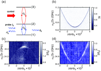
Our artificial atom is a macroscopic size ( 1 m) superconducting loop interrupted by four Josephson junctions, which has been used as a two-level system or a flux qubit Mooij et al. (1999); Chiorescu et al. (2003) in earlier experiments. We exploit three lowest states with energies , schematically represented in Fig. 1a. The device parameters are designed such that all relevant transition frequencies of the three-level system () fall within the frequency band of our experimental setup limited by 40 GHz. The atomic levels are controlled by the external magnetic flux thread through the loop , where is the flux quantum and is the deviation from . The loop is inductively coupled to a transmission line (open 1D space) via a mutual kinetic inductance Abdumalikov et al. (2008). At the degeneracy point the atom has a ladder type energy level structure. Due to symmetry of eigenstate wavefunctions and transitions are allowed, while the transition is forbidden. The coplanar transmission line with the characteristic impedance was made by patterning a gold film deposited on a silicon substrate. In the middle of the chip, the central conductor of the waveguide is narrowed and replaced by an aluminium strip. Our experiment is performed in a dilution refrigerator at a temperature of 40 mK.
In the rotating wave approximation, the three-level system under the drive of two fields with frequencies and , where and presents small detunings from corresponding resonances and , is described by the Hamiltonian
| (1) |
Here is the atomic projection/transition operator, and and are the probe and control dipole interaction energies for the transitions and , respectively. Under the influence of the two fields in the transmission line with the actual current values given by and . Here we assume that our pointlike atom is situated at and the waves from microwave sources and propagate in the transmission line. The dipole matrix element can be presented in the form with the dimensionality of a magnetic flux, where is the dimensionless matrix element (), is the line-atom mutual inductance, and is the amplitude of the persistent current in the loop.
The atomic dynamics is described by the Markovian master equation for the density matrix ,
| (2) |
with the Lindblad term
| (3) |
Here is the damping rate of the off-diagonal terms (dephasing) and is the relaxation rate between the levels and (). In the ladder-type three-level atom the transition is omitted, since . In our case the condition () is fulfilled and the absence of thermal excitations ( = 0 and = 0) is guaranteed.
One can show that the atom interacting only with continuum modes of 1D open space generates a scattered wave at the probe frequency Astafiev et al. (2010)
| (4) |
where can be straightforwardly found in the stationary conditions (), when the master equation reduces to a set of linear algebraic equations. The transmission coefficient found as a ratio of the resulting current (at ) to the incident one and for weak probe drive , the transmission coefficient is
| (5) |
The complex transmission coefficient is monitored using a vector network analyzer in the frequency range from 5 GHz to 13 GHz. Measuring versus probing frequency and the magnetic flux , the resonant transition frequency is revealed as a sharp dip in (dark line in Fig. 1b). By fitting we find that the minimal frequency reaches 10.165 GHz at , and the persistent current in the loop is nA. Next analyzing the spectroscopy line shape of at , the relaxation and dephasing rates are found to be s-1 ( MHz) and s-1 ( MHz) Astafiev et al. (2010). Non-radiative emission in such systems is expected to be negligible with corresponding relaxation rate less than s-1, measured in earlier experiments Yoshihara et al. (2006). Therefore, we conclude that the relaxation is caused solely by the quantum noise of open 1D space defined by the rate and derive the mutual inductance between the loop and the transmission line to be pH.
The transition frequencies and cannot be probed in the direct transmission, since they exceed the high frequency cutoff (13 GHz) of the cryogenic amplifier. To find them we use two-tone spectroscopy: The frequency of a weak probe tone, , is adjusted to (found from the data shown in Fig. 1b), where the transmission is minimal (). Next, the transmission is continuously monitored, while the second (control) tone frequency is swept. When is in resonance with the corresponding transitions, total population and is decreased and, therefore, is enhanced, revealing the spectral lines in plot of . Fig. 1c and Fig. 1d show traces of the spectroscopy lines for and , respectively. Due to symmetry of eigenstate wave functions, the selection rule in our system prohibits transitions between states and at , which is seen in Fig. 1c as the vanishing spectroscopy signal. At the same time, the matrix elements for to and to transitions reach their maximum. Thus at the degeneracy point, we have a ladder type three-level quantum system Scully and Zubairy (1997), schematically represented in Fig. 1a, with two allowed and one forbidden transitions. The enhancement of transmission (suppression of reflection) in Fig. 1c is already a signature of the single-atom EIT, which we study in detail at .
Electromagnetic response of the single atom is naturally characterized by polarizability, (rather than susceptibility used to characterize the optical response of macroscopic media). The polarizability is a ratio of the atomic dipole moment to the excitation field (in our case defined as the induced magnetic flux in the loop to the incident wave current amplitude). The atom scatters waves Astafiev et al. (2010) and the polarizability is related to the reflection and the transmission according to . The polarizability can be presented as with the real and imaginary parts and related to dispersion and reflection, respectively. Fig. 2a demonstrates transmission Re for different amplitudes (associated with absorption in EIT for media), while Fig. 2b shows dispersion curves of Im. The probing amplitude in the measurements is fixed to MHz. In the absence of control field (black curves in Fig. 2), the wave is strongly reflected, exhibiting the Lorentzian dip in Re, while Im follows the typical anomalous dispersion curve in vicinity of the resonant transition. With increasing control field amplitude , the dip is split, and at the strongest drive ( = 44 MHz) the dip is completely suppressed, exhibiting full transparency at the exact resonance () and a dispersion curve typical for EIT in Fig. 2b. Figures 2c and 2d show our calculations of Re and Im respectively with s-1 ( MHz), which is comparable to . In atomic physics, the transmission window much narrower than the absorption dip appears already for weak control amplitude () because of small dephasing between levels and Fleischhauer et al. (2005).
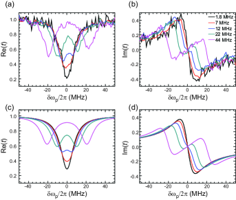
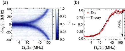
Figure 3a summarizes the data of Figs. 2a-b, showing the power transmission coefficient as a function of control field amplitude . The splitting at the strong drive is known as the Autler-Townes splitting Autler and Townes (1955). It arises due to Rabi splitting of levels and . In the present experiments we could induce larger than 100 MHz splitting. Figures 2 and 3a demonstrate that the transmission strongly depends on the control field , and, therefore, the latter can be used to control transmission and reflection for the probing wave. However, all the power can be reflected or transmitted only in extreme cases of or , respectively. The power transmission at the exact probing wave resonance () is presented in Fig. 3b. The transmitted wave extinction exhibits contrast of 96%, which demonstrates that the artificial atom can be used as a highly efficient directional switch (or mirror) for propagating waves. The power extinction is close to the ideal case of 100%, which is possible in the absence of pure dephasing for the probe transition () and if all the incident power interacts with the atom. In such a case the power transmission is presented by the simple formula
| (6) |
The black curve in Fig. 3b shows calculation of from Eq. (5) as for our case of weak pure dephasing, which slightly deviates from Eq. (6).
In conclusion, we have demonstrated operation of a quantum switch for propagating waves, which allows the propagating waves to be fully transmitted or backscattered. The experiment suggests interesting applications in photonics and optical quantum computation. It also demonstrates possibility of controlling individual atoms coupled to a 1D transmission line, which can be used, e.g., for photonic quantum information processing Kok et al. (2007).
References
- Scully and Zubairy (1997) M. O. Scully and M. S. Zubairy, Quantum Optics (Cambridge University Press, Cambridge, England, 1997).
- Harris et al. (1990) S. E. Harris, J. E. Field, and A. Imamoglu, Phys. Rev. Lett. 64, 1107 (1990).
- Fleischhauer et al. (2005) M. Fleischhauer, A. Imamoglu, and J. P. Marangos, Rev. Mod. Phys. 77, 633 (2005).
- Gerhardt et al. (2007) I. Gerhardt, G. Wrigge, P. Bushev, G. Zumofen, M. Agio, R. Pfab, and V. Sandoghdar, Phys. Rev. Lett. 98, 033601 (2007).
- Wrigge et al. (2008) G. Wrigge, I. Gerhardt, J. Hwang, G. Zumofen, and V. Sandoghdar, Nature Physics 4, 60 (2008).
- Tey et al. (2008) M. K. Tey, C. Zilong, S. A. Aljunid, B. Chng, F. Huber, G. Maslennikov, and C. Kurtsiefer, Nature Phys. 4, 924 (2008).
- Vamivakas et al. (2007) A. N. Vamivakas, M. Atatüre, J. Dreiser, S. T. Yilmaz, A. Badolato, A. K. Swan, B. B. Goldberg, A. Imamoglu, and M. S. Ünlü, Nano Lett. 7, 2892 (2007).
- Muller et al. (2007) A. Muller, E. B. Flagg, P. Bianucci, X. Y. Wang, D. G. Deppe, W. Ma, J. Zhang, G. J. Salamo, M. Xiao, and C. K. Shih, Phys. Rev. Lett. 99, 187402 (2007).
- Hwang et al. (2009) J. Hwang, M. Pototschnig, R. Lettow, G. Zumofen, A. Renn, S. Götzinger, and V. Sandoghdar1, Nature 460, 76 (2009).
- Astafiev et al. (2010) O. Astafiev, A. M. Zagoskin, A. A. Abdumalikov Jr., Y. A. Pashkin, T. Yamamoto, K. Inomata, Y. Nakamura, and J. S. Tsai, Science 327, 840 (2010).
- Nakamura et al. (1999) Y. Nakamura, Y. A. Pashkin, and J. S. Tsai, Nature 398, 786 (1999).
- Martinis et al. (2002) J. M. Martinis, S. Nam, J. Aumentado, and C. Urbina, Phys. Rev. Lett. 89, 117901 (2002).
- Chiorescu et al. (2003) I. Chiorescu, Y. Nakamura, C. J. P. M. Harmans, and J. E. Mooij, Science 299, 1869 (2003).
- Wallraff et al. (2004) A. Wallraff, D. I. Schuster, A. Blais, L. Frunzio, R.-S. Huang, J. Majer, S. Kumar, S. M. Girvin, and R. J. Schoelkopf, Nature 431, 162 (2004).
- Houck et al. (2007) A. A. Houck, D. I. Schuster, J. M. Gambetta, J. A. Schreier, B. R. Johnson, J. M. Chow, L. Frunzio, J. Majer, M. H. Devoret, S. M. Girvin, et al., Nature 449, 328 (2007).
- Schuster et al. (2007) D. I. Schuster, A. A. Houck, J. A. Schreier, A. Wallraff, J. M. Gambetta, A. Blais, L. Frunzio, J. Majer, B. Johnson, M. H. Devoret, et al., Nature 445, 515 (2007).
- Fragner et al. (2008) A. Fragner, M. Göppl, J. M. Fink, M. Baur, R. Bianchetti, P. J. Leek, A. Blais, and A. Wallraff, Science 322, 1357 (2008).
- Astafiev et al. (2007) O. Astafiev, K. Inomata, A. O. Niskanen, T. Yamamoto, Y. A. Pashkin, Y. Nakamura, and J. S. Tsai, Nature 449, 588 (2007).
- Hofheinz et al. (2009) M. Hofheinz, H. M. Wang, A. Ansmann, R. C. Bialczak, E. Lucero, M. Neeley, A. D. O’Connell, D. Sank, J. Wenner, J. M. Martinis, et al., Nature 459, 546 (2009).
- Murali et al. (2004) K. V. R. M. Murali, Z. Dutton, W. D. Oliver, D. S. Crankshaw, and T. P. Orlando, Phys. Rev. Lett. 93, 087003 (2004).
- Baur et al. (2009) M. Baur, S. Filipp, R. Bianchetti, J. M. Fink, M. Göppl, L. Steffen, P. J. Leek, A. Blais, and A. Wallraff, Phys. Rev. Lett. 102, 243602 (2009).
- Sillanpää et al. (2009) M. A. Sillanpää, J. Li, K. Cicak, F. Altomare, J. I. Park, R. W. Simmonds, G. S. Paraoanu, and P. J. Hakonen, Phys. Rev. Lett. 103, 193601 (2009).
- Kelly et al. (2009) W. R. Kelly, Z. Dutton, J. Schlafer, B. Mookerji, T. A. Ohki, J. S. Kline, and D. P. Pappas, arXiv:0912.3291 (2009).
- Mooij et al. (1999) J. E. Mooij, T. P. Orlando, L. Levitov, L. Tian, C. H. van der Wal, and S. Lloyd, Science 285, 1036 (1999).
- Abdumalikov et al. (2008) A. A. Abdumalikov, O. Astafiev, Y. Nakamura, Y. A. Pashkin, and J.-S. Tsai, Phys. Rev. B 78, 180502(R) (2008).
- Yoshihara et al. (2006) F. Yoshihara, K. Harrabi, A. O. Niskanen, Y. Nakamura, and J. S. Tsai, Phys. Rev. Lett. 97, 167001 (2006).
- Autler and Townes (1955) S. H. Autler and C. H. Townes, Phys. Rev. 100, 703 (1955).
- Kok et al. (2007) P. Kok, W. J. Munro, T. C. Ralph, J. P. Dowling, and G. J. Milburn, Rev. Mod. Phys. 79, 135 (2007).