Topological defects in graphene: dislocations and grain boundaries
Abstract
Topological defects in graphene, dislocations and grain boundaries, are still not well understood despites the considerable number of experimental observations. We introduce a general approach for constructing dislocations in graphene characterized by arbitrary Burgers vectors as well as grain boundaries, covering the whole range of possible misorientation angles. By using ab initio calculations we investigate thermodynamic and electronic properties of these topological defects, finding energetically favorable symmetric large-angle grain boundaries, strong tendency towards out-of-plane deformation in the small-angle regimes, and pronounced effects on the electronic structure. The present results show that dislocations and grain boundaries are important intrinsic defects in graphene which may be used for engineering graphene-based nanomaterials and functional devices.
pacs:
61.48.Gh, 73.22.Pr, 61.72.Lk, 61.72.MmI INTRODUCTION
The isolation of graphene, a two-dimensional (2D) material with extraordinary physical properties, has opened new horizons for physics exploration and future technology.Geim07 ; Katsnelson07 In 2D, properties of materials can be heavily affected by structural irregularities. Graphene edges and point defects such as vacancies have been extensively investigated over the past few years.CastroNeto09 However, these types of disorder have to be distinguished from dislocations and grain boundaries, structural defects characterized by the finite values of their respective topological invariants, Burgers vectors and misorientation angles.Nelson02 Such topological defects introduce non-local disorder into the crystalline lattice. Surprisingly, dislocations and grain boundaries in graphene are still not well understood despite the growing number of experimental observations.
The first experimental results date back to the scanning tunneling microscopy (STM) studies of tilt grain boundaries on graphite surfaces,Albrecht88 fueled by their confusion with biological macromolecules.Clemmer91 ; Heckl92 More recently it has been shown that grain boundary defects have a dramatic influence on the local electronic properties of graphite.Cervenka09 ; Cervenka09b An individual dislocation in free-standing graphene layers has been imaged using transmission electron microscopy (TEM).Hashimoto04 Topological defects resulting from either kinetic factors or substrate imperfections have also been reported for epitaxial graphene grown on SiC,Miller09 Ir(111)Coraux08 ; Loginova09 and polycrystalline Ni surfaces.Park10
Here, we describe a systematic approach for constructing arbitrary dislocations and grain boundaries in graphene starting from disclinations as the elementary topological defects. Then, by using ab initio calculations we explore energetic and electronic properties of the proposed structures finding a number of intriguing features such as two energetically favorable symmetric large-angle grain boundaries, strong tendency towards out-of-plane deformation in the small-angle regimes, and pronounced effects on the electronic structure. Our results highlight the possible important role of dislocations and grain boundaries in practical graphene samples.
The present paper is organized in the following manner. In Section II we describe our first-principles computational methodology. Section III.1 presents a systematic approach for constructing atomic structures of dislocations and grain boundaries in graphene. Sections III.2 and III.3 are devoted to the discussion of energetics and electronic structure of the constructed topological defects, respectively. Section IV concludes our work.
II COMPUTATIONAL METHODS
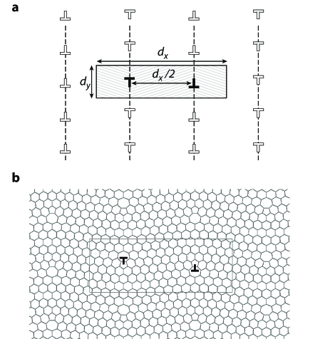
First-principles calculations have been performed using the spin-polarized density functional theory (DFT) scheme implemented in the SIESTA code.SIESTA The generalized gradient approximation (GGA) exchange-correlation density functional Perdew96 was employed together with a double- plus polarization basis set, norm-conserving pseudopotentials Troullier91 and a mesh cutoff of 200 Ry. The computational model involved two parallel equally spaced grain boundaries in a rectangular simulation supercell in order to satisfy periodic boundary conditions (see Fig. 1). The distance between the neighboring dislocations along the boundary line, and thus the misorientation angle , are changed by varying the supercell dimension. The supercell dimension was 4 nm in all studied models. The chosen supercell construction allows one to reduce the error due to elastic interactions between the neighboring grain boundaries.Blase00 We verified that a larger inter-boundary separation ( nm) produces only a negligible change in the calculated grain boundary energy in both small-angle and large-angle regimes. Both atomic coordinates and supercell dimensions were optimized using the conjugate-gradient algorithm and a 0.04 eV/Å maximum force convergence criterion. The Brillouin zone was sampled using 2 -points along the axis and a consistent number of approximately -points along the axis ( in nm). The scanning tunneling microscopy (STM) images were simulated using a previously developed methodMeunier99 ; Ishigami04 employing the calculated local density-of-states in the energy window of eV around the charge neutrality point.
III DISCUSSION OF RESULTS
III.1 Atomic structure of topological defects:
a systematic approach
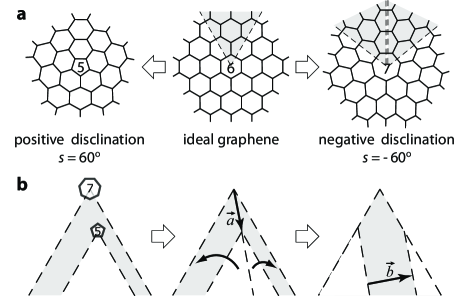
In truly 2D materials only edge dislocations are possible since the Burgers vector , a topological invariant which reflects the magnitude and direction of the crystalline lattice distortion produced by a dislocation, is constrained to lie in the material’s plane. One can imagine such dislocation as a result of embedding a semi-infinite strip of width into an otherwise perfect 2D crystalline lattice. As a guiding rule for constructing atomic structures of dislocations in graphene we assume that the dislocation core is free from under- or over-coordinated carbon atoms; that is, we aim at minimizing the energy of the dislocation core and, thus, the total formation energy of the dislocation.Hirth92 To develop such construction we adopt a membrane theory approach which views a dislocation as a pair of positive and negative disclinations, i.e. topological defects obtained by removing and adding a semi-infinite wedge of material to an otherwise perfect crystalline lattice, respectively.Seung88 As shown in Figure 2(a), () disclination in graphene contains a five (seven) membered ring in its core while the original three-fold coordination of all carbon atoms is preserved. Figure 2(b) schematically shows the equivalence of a pair of complementary disclinations to a dislocation. Moreover, we find that on graphene lattice the distance between two disclinations, , is related to the resulting Burgers vector by a simple relation, (for proof see Appendix A).
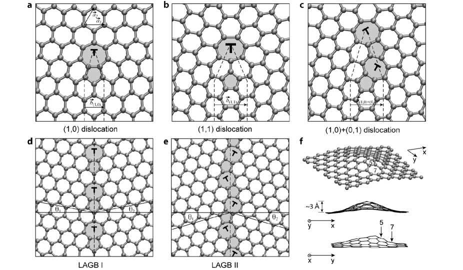
Since any Burgers vector is a proper translational vector of graphene lattice, i.e. (; Å, the nearest neighbor interatomic distance in graphene), we will use the pair of integers as a descriptor of dislocations in graphene. This notation is analogous to the chirality indices used to describe the structure of carbon nanotubes. The core of the shortest Burgers vector dislocation (1,0) ( Å) contains an edge-sharing heptagon-pentagon pair as shown in Figure 3(a). The dislocation inserts a semi-infinite strip of atoms along the armchair high-symmetry direction in graphene while its Burgers vector is oriented along the zigzag direction. This simplest dislocation structure has been extensively studied in the context of plastic deformation of carbon nanotubes,Nardelli98 nanotubes junctionsChico96 as well as graphene itself.Ewels02 ; Carpio08 The second member of the family, the (1,1) dislocation, has a larger Burgers vector ( Å) and inserts a semi-infinite strip along the zigzag direction of graphene (see Fig. 3(b)). Alternatively, the core of the dislocation with the same Burgers vector can be constructed from two Å dislocations, (1,0) and (0,1), e.g. as shown in Figure 3(c). The simple method outlined above can be used to build dislocation with even longer Burgers vectors, inevitably leading to larger elastic energies.
Grain boundaries, the interfaces between the domains of material with different crystallographic orientations, are commonly viewed as periodic arrays of dislocations.Read50 Particularly, in 2D materials such as graphene, one-dimensional (1D) chains of edge dislocations constitute tilt grain boundaries. Mutual orientation of the two crystalline domains is described by the misorientation angle ( in graphene), a topological invariant defined as shown in Fig. 3(d). Another parameter describes the inclination of the boundary line with respect to the symmetric configuration (). We limit our consideration to only symmetric ones since asymmetric configurations tend to result in diverging elastic energies.Carraro93 Importantly, due to the presence of two high-symmetry directions in graphene, armchair and zigzag, both misorientation angles close to 0∘ and 60∘ can be considered as small-angle grain boundaries along these two directions, respectively. Aligning (1,0) dislocations along the grain boundary line results in a discrete set of misorientation angles in accordance with Frank’s equationHirth92
| (1) |
where is one of the possible values for the distance between the neighboring dislocations. Large values of correspond to small-angle grain boundaries along the armchair direction. The closest possible packing of (1,0) dislocations results in the large-angle grain boundary structure shown in Fig. 3(d). This configuration characterized by (LAGB I) has already been suggested in the literature.Heckl92 ; Simonis02 In order to cover the the range of between 21.8∘ and 60∘, it is necessary to introduce another type of dislocations, e.g. (1,1) dislocations:
| (2) |
The smallest value of gives rise to the LAGB I structure rotated by 180∘. Large separations correspond to small-angle grain boundaries along the zigzag direction. Alternatively, small-angle grain boundaries along this direction can be constructed using the (1,0)+(0,1) pairs with the densest possible packing of dislocations leading to the structure LAGB II with (Fig. 3(e)). Hence, it is possible to construct symmetric grain boundaries covering the whole range of from 0∘ to 60∘ by using (1,0) dislocations and either (1,1) dislocations or (1,0)+(0,1) dislocation pairs. We stress that the present construction is equally applicable to tilt grain boundaries in both graphene and graphite.
III.2 Energetics of topological defects
In order to determine the energetically preferred structures and to understand the basic thermodynamic properties of grain boundaries in graphene, we perform first-principles calculations on models containing a pair of complementary dislocations in periodic 2D supercell as described in Section II. The results are presented as a diagram of grain boundary energies per unit length as a function of (Fig. 4). We first discuss the case of perfectly flat grain boundaries (filled symbols) which corresponds to the limit of strong binding to a flat substrate and analogous to the case of grain boundaries in bulk materials. The diagram clearly reveals both armchair and zigzag small-angle regimes with grain boundary formation energies converging to zero for and . A detailed study of the armchair small-angle region () shows that the grain boundary energies are well described by the Read-Shockley equationRead50
| (3) |
where is the shear modulus, the Poisson’s ratio. The core radius encompasses the energy of the dislocation core. In Eq. (3), or for armchair and zigzag small-angle grain boundaries, respectively. Using the values of elastic constants which correspond to our first principles model of graphene (see Appendix B) a least-squares fit to the Read-Shockley equation (solid red curve in Fig. 4) yields Å. This value is in good agreement with the recently reported Å fitted to local density approximation calculations.Ertekin09 As we outlined above, there are several grain boundary structures possible for . In order to determine the lowest energy structure, we compare the energies of grain boundaries constructed from (1,1) dislocations and (1,0)+(0,1) dislocation pairs. In addition, for the grain boundary can be constructed either from equally spaced (1,0) and (0,1) dislocations (disperse case) or from closely bound pairs (paired case). Figure 4 shows that the disperse (1,0)+(0,1) grain boundaries in flat graphene are the lowest-energy structures for . More generally, this also implies that only the shortest Burgers vector (1,0) dislocation is sufficient for constructing the most stable grain boundary structures at any given . Remarkably, the two large-angle structures discussed above, LAGB I and LAGB II, have particularly low formation energies of 0.338 eV/Å and 0.284 eV/Å, respectively. Favorable energetics suggests possible abundance of these two structural motifs. Moreover, for all possible values of the grain boundary energies are well below the energies of 1 eV/Å predicted for graphene edges.Koskinen08
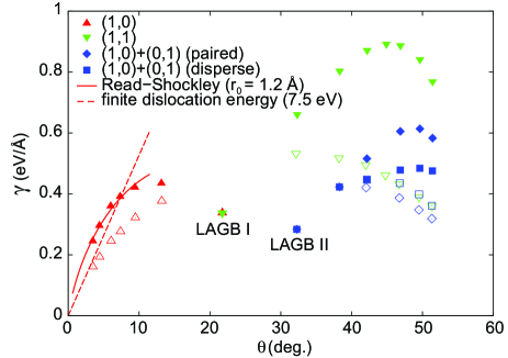
The case of free-standing 2D materials is notably different since buckling in the third dimension allows an exchange of in-plane elastic energy for bending energy. This leads to efficient screening of the in-plane strain field resulting in the finite formation energies of dislocations.Seung88 While we find that the large-angle grain boundaries in graphene are flat, for and buckling effectively reduces the grain boundary energies (Fig. 4, empty symbols). In the small-angle regimes, grain boundary energy is expected to scale linearly with :
| (4) |
where is the formation energy of the dislocation. By extrapolating the grain boundary energies to , we obtain a formation energy of 7.5 eV for the (1,0) dislocation (see Appendix C). This value is comparable to the formation energies of typical point defects in graphene, e.g. vacancies (7.6 eV) and Stone-Wales defects (4.8 eV).Li05 Out-of-plane buckling results in a prolate hillock appearance of dislocations on the flat graphene surface (Fig. 3(f)) in agreement with the experimental observations of Coraux et al.Coraux08 The height of the protrusion around the (1,0) dislocation is 3 Å and its top is shifted with respect to the dislocation core. Interestingly, out-of-plane distortion makes the paired case (1,0)+(0,1) grain boundaries more stable, thus inverting the sign of effective interaction between the dislocation dipoles. The situations in which graphene is bound to substrate can be viewed as intermediate between the flat and buckled regimes.
III.3 Electronic structure of topological defects
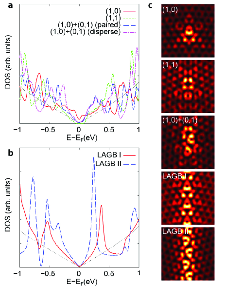
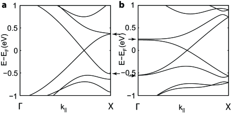
Finally, we address the electronic structure of topological defects in graphene. Figures 5(a) and 5(b) show the calculated density-of-states plots for small-angle and stable large-angle grain boundaries in graphene. All studied defect configurations introduce van Hove singularities within 0.5 eV below and above the Dirac point ( eV), in accordance with the scanning tunneling spectroscopy (STS) observations for the majority of grain boundaries in graphite reported in Refs. Cervenka09, ; Cervenka09b, . The van Hove singularities are the signatures of one-dimensional states localized at the interface as shown by simulated STM images (Fig. 5(c)). This relation is further corroborated by considering the electronic band structures of large-angle grain boundary models shown in Figure 6. However, we do not observe any zero-energy states or defect-induced magnetic moments typical of zigzag edgesSon06 ; Yazyev08b and single-atom defectsYazyev07 ; Yazyev08 ; Yazyev10 in graphene. Pronounced changes in the low-energy part of electron spectrum make it possible to identify the discussed extended defects using STM. In order to facilitate the attribution of experimental observations to the proposed structures we provide their simulated atomic-scale STM fingerprints (Fig. 5(c)). The common feature of all images is the crescent- or ring-shaped appearance of 5-membered rings. The STM images of grain boundaries formed by (1,0)+(0,1) dislocations show the lack of mirror symmetry compared to the (1,0) or (1,1) derived structures, as follows from the atomic structures of these grain boundaries.
IV CONCLUSIONS
We have developed a systematic approach for constructing atomic structures of topological defects in graphene. Our first-principles calculations revealed a number of intriguing features in the energetics of grain boundaries. In particular, we have found two large-angle grain boundary structures with particularly low formation energies as well as two distinct small-angle regimes which correspond to the grain boundaries oriented close to the armchair and zigzag directions, respectively. In free-standing graphene the small-angle grain boundaries show pronounced tendency to an out-of-plane buckling which further reduces their formation energies. We have also found that all the studied topological defects have strong effects on the electronic structure and can be identified using STM. These results show that dislocations and grain boundaries are important intrinsic defects in graphene which may be used for engineering graphene-based nanomaterials and functional devices.
ACKNOWLEDGMENTS
We are grateful to Y.-W. Son and D. Strubbe for their suggestions. This work was supported by National Science Foundation Grant No. DMR07-05941 and by the Director, Office of Science, Office of Basic Energy Sciences, Division of Materials Sciences and Engineering Division, U.S. Department of Energy under Contract No. DE-AC02-05CH11231. O. V. Y. acknowledges financial support of the Swiss National Science Foundation (grant No. PBELP2-123086). Computational resources have been provided by NERSC and TeraGrid.
Appendix A Relation between the dislocation dipole and the Burgers vector
Theorem. If a dislocation is constructed from a pair of disclinations, then its Burgers vector and vector connecting the disclinations are related as
| (5) |
Proof. We consider the following construction in which a negative disclination inserts sector at point and a complementary positive disclination removes sector at point in a continuous two-dimensional sheet.
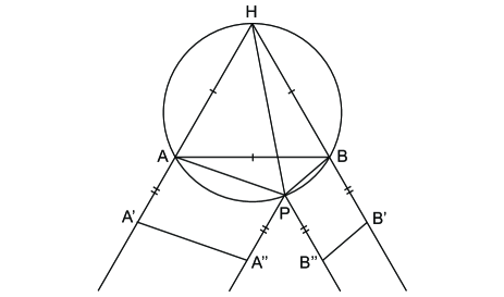
The condition of continuity requires (), as well as . In addition, we require that, after the described procedure, pairs of segments and as well as and form straight lines. That is,
| (6) |
Hence,
| (7) |
By construction , thus and . Due to the latter property, quadrilateral can be inscribed in a circle and, thus, from Ptolemy’s theorem it follows that
| (8) |
Finally,
| (9) |
Appendix B Structural and elastic constants of graphene from first principles
In order to fit the results of our calculations of small-angle grain boundaries to the continuum-model Read-Shockley equation, we use elastic constants and the interatomic distance of graphene which correspond to the present first-principles model of graphene. Elastic constants are obtained from the constrained variable cell calculations in which one of the rectangular supercell dimensions was fixed while the other one varies in order to minimize the total energy. This allowed us to determine Young’s modulus and Poisson’s ratio while the shear modulus was calculated using the following relation:S1
| (10) |
The calculated moduli correspond to 3.35 Å thickness of the graphene layer. Our values are in good agreement with other values reported in literature (see Table 1).
| (Å) | (TPa) | (GPa) | ||
|---|---|---|---|---|
| this work | 1.433 | 1.052 | 0.206 | 436 |
| Exp. (graphite) S2 | 1.020.03 | 0.160.03 | ||
| Exp. (graphene) S3 | 1.00.1 | |||
| Theory S4 | 1.050 | 0.186 | ||
| Theory S5 | 1.010.03 | 0.210.01 |
Appendix C Formation energy of the buckled (1,0) dislocation in graphene
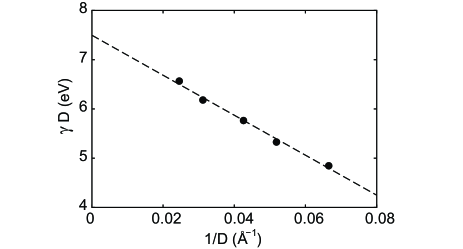
Figure 4 shows that the energies of the buckled small-angle armchair grain boundaries do not achieve the expected linear dependence (Eq. (4)) in the range of studied misorientation angles . The maximum separation between the neighboring (1,0) dislocations along the boundary line we could afford in our demanding first-principles calculations is 4 nm (corresponds to ). At this , the screening of the in-plane elastic field is still insufficient to decouple the neighboring dislocations along the grain boundary direction. However, we observe that the energy per dislocation shows a clear linear dependence with . By extrapolating the values of grain boundary energies for to the limit of (that is, ), we obtain an estimate of the formation energy of an isolated buckled (1,0) dislocation eV.
References
- (1) A. K. Geim and K. S. Novoselov, Nature Mater. 6, 183 (2007).
- (2) M. I. Katsnelson, Materials Today 10, 20 (2007).
- (3) A. H. Castro Neto, F. Guinea, N. M. R. Peres, K. S. Novoselov, and A. K. Geim, Rev. Mod. Phys. 81, 109 (2009).
- (4) D. R. Nelson, Defects and geometry in condensed matter physics (Cambridge Univ. Press, Cambridge, 2002).
- (5) T. R. Albrecht, H. A. Mizes, J. Nogami, S.-i. Park, and C. F. Quate, Appl. Phys. Lett. 52, 362 (1988).
- (6) C. R. Clemmer and T. P. Beebe Jr., Science 251, 640 (1991).
- (7) W. M. Heckl and G. Binnig, Ultramicroscopy 42, 1073 (1992).
- (8) J. Červenka and C. F. J. Flipse, Phys. Rev. B 79, 195429 (2009).
- (9) J. Červenka, M. I. Katsnelson, and C. F. J. Flipse, Nature Phys. 5, 840 (2009).
- (10) A. Hashimoto, K. Suenaga, A. Gloter, K. Urita, and S. Iijima, Nature (London) 430, 870 (2004).
- (11) D. L. Miller, K. D. Kubista, G. M. Rutter, M. Ruan, W. A. de Heer, Ph. N. First, and J. A. Stroscio, Science 324, 924 (2009).
- (12) J. Coraux, A. T. N’Diaye, C. Busse, and T. Michely, Nano Lett. 8, 565 (2008).
- (13) E. Loginova, S. Nie, K. Thurmer, N. C. Bartelt, and K. F. McCarty, Phys. Rev. B 80, 085430 (2009).
- (14) H. J. Park, J. Meyer, S. Roth, and V. Skákalová, Carbon 48, 1088 (2010).
- (15) J. M. Soler, E. Artacho, J. D. Gale, A. Garcia, J. Junquera, P. Ordejón, and D. Sanchez-Portal, J. Phys.: Condens. Matter 14, 2745 (2002).
- (16) J. P. Perdew, K. Burke, and M. Ernzerhof, Phys. Rev. Lett. 77, 3865 (1996).
- (17) N. Troullier and J. L. Martins, Phys. Rev. B 43, 1993 (1991).
- (18) X. Blase, K. Lin, A. Canning, S. G. Louie, and D. C. Chrzan, Phys. Rev. Lett. 84, 5780 (2000).
- (19) V. Meunier and Ph. Lambin, Phys. Rev. Lett. 81, 5588 (1999).
- (20) M. Ishigami, H. J. Choi, S. Aloni, S. G. Louie, M. L. Cohen, and A. Zettl, Phys. Rev. Lett. 93, 196803 (2004).
- (21) J. P. Hirth and J. Lothe, Theory of dislocations (Wiley, New York, 1982).
- (22) H. S. Seung and D. R. Nelson, Phys. Rev. A 38, 1005 (1988).
- (23) M. B. Nardelli, B. I. Yakobson, and J. Bernholc, Phys. Rev. Lett. 81, 4656 (1988).
- (24) L. Chico, V. H. Crespi, L. X. Benedict, S. G. Louie, and M. L. Cohen, Phys. Rev. Lett. 76, 971 (1996).
- (25) C. P. Ewels, M. I. Heggie, and P. R. Briddon, Chem. Phys. Lett. 351, 1782 (2002).
- (26) A. Carpio, L. L. Bonilla, F. de Juan, and M. A. H. Vozmediano, New J. Phys. 10, 053021 (2008).
- (27) W. T. Read and W. Shockley, Phys. Rev. 78, 275 (1950).
- (28) C. Carraro and D. R. Nelson, Phys. Rev. E 48, 3082 (1993).
- (29) P. Simonis, C. Goffaux, P. A. Thiry, L. P. Biro, Ph. Lambin, and V. Meunier, Surf. Sci. 511, 319 (2002).
- (30) E. Ertekin, D. C. Chrzan, and M. S. Daw, Phys. Rev. B 79, 155421 (2009).
- (31) P. Koskinen, S. Malola, and H. Häkkinen, Phys. Rev. Lett. 101, 115502 (2008).
- (32) L. Li, S. Reich, and J. Robertson, Phys. Rev. B 72, 184109 (2005).
- (33) Y.-W. Son, M. L. Cohen, and S. G. Louie, Nature (London) 444, 347 (2006).
- (34) O. V. Yazyev and M. I. Katsnelson, Phys. Rev. Lett. 100, 047209 (2008).
- (35) O. V. Yazyev and L. Helm, Phys. Rev. B 75, 125408 (2007).
- (36) O. V. Yazyev, Phys. Rev. Lett. 101, 037203 (2008).
- (37) O. V. Yazyev, Rep. Prog. Phys. 73, 056501 (2010).
- (38) L. D. Landau and E. M. Lifschitz, Theory of Elasticity (Butterworth Heinemann, Oxford, 1986).
- (39) O. L. Blakslee, D. G. Proctor, E. J. Seldin, G. B. Spence, and T. Weng, J. Appl. Phys. 41, 3373 (1970).
- (40) C. Lee, X. Wei, J. W. Kysar, and J. Hone, Science 321, 385 (2008).
- (41) F. Liu, P. Ming, and J. Li, Phys. Rev. B 76, 064120 (2007).
- (42) H. Zhao, K. Min, and N. R. Aluru, Nano Lett. 9, 3012 (2009).