Quantum and classical resonant escapes of a strongly-driven Josephson junction
Abstract
The properties of phase escape in a dc SQUID at 25 mK, which is well below quantum-to-classical crossover temperature , in the presence of strong resonant ac driving have been investigated. The SQUID contains two Nb/Al-AlOx/Nb tunnel junctions with Josephson inductance much larger than the loop inductance so it can be viewed as a single junction having adjustable critical current. We find that with increasing microwave power and at certain frequencies and /2, the single primary peak in the switching current distribution, which is the result of macroscopic quantum tunneling of the phase across the junction, first shifts toward lower bias current and then a resonant peak develops. These results are explained by quantum resonant phase escape involving single and two photons with microwave-suppressed potential barrier. As further increases, the primary peak gradually disappears and the resonant peak grows into a single one while shifting further to lower . At certain , a second resonant peak appears, which can locate at very low depending on the value of . Analysis based on the classical equation of motion shows that such resonant peak can arise from the resonant escape of the phase particle with extremely large oscillation amplitude resulting from bifurcation of the nonlinear system. Our experimental result and theoretical analysis demonstrate that at , escape of the phase particle could be dominated by classical process, such as dynamical bifurcation of nonlinear systems under strong ac driving.
pacs:
74.50.+r, 05.45.-a, 85.25.Cp, 03.75.LmI Introduction
Devices based on Josephson junctions are not only the key elements for the realization of superconducting qubits makh01 but also testbeds for the study of macroscopic quantum phenomena and nonlinear dynamics. In these studies, response of the device to resonant or near-resonant microwave fields provides insights to understand their behavior. Numerous works have been reported in the literature, such as the demonstration of energy level quantization in current biased junctions martinis85 ; clarke88 ; wallraff03 ; bauch06 ; xu03 and Rabi oscillations in phase qubits. xu03 ; yu02 ; martinis02 These experiments are usually performed at low temperatures ( 20 mK) in relatively weak microwave field. Under such conditions, the junctions behave quantum-mechanically and the phase particle may escape from the potential well by macroscopic quantum tunneling (MQT) from ground state and/or via photon-assisted tunneling (PAT) from excited states, depending on the bias current and the microwave frequency . When the switching current distribution of a current biased junction is measured, MQT from ground state manifests as a peak, which we call the primary peak, centered slightly below the critical current of the junction. In the case of the PAT process, a resonant peak at a slightly lower current could be observed in addition to the primary peak in .
The phase escape of a Josephson junction at low temperatures exhibits a number of interesting phenomena as the microwave power increases, which can be described as follows. (1) As mentioned above, when the frequency matches the bias current dependent energy level spacing between the ground and the first excited states at that is close to and is low, the excited state population will be enhanced but remains 1. This results in a higher escape rate at since . Consequently, a resonant peak at appears in . Because is low, the system’s potential and level spacing are essentially unperturbed by microwave field, as reflected in the unchanged position of the primary peak. (2) When corresponds to the level spacing at a resonance current that is well below and the microwave field is weak, there will be no resonant peak since is still too low to observe at . In this case, as is increased, the position of the primary peak will move continuously to lower bias currents due to the suppression of the effective potential barrier. fistul03 ; fistul00 ; sun08 This suppression is particularly strong at resonance, leading to a significant increase of and thus a visible resonant peak. (3) If matches a fraction of the level spacing and satisfies , where is the level spacing between the ground state and the th excited state and is a small positive integer, the multiphoton PAT process occurs and the corresponding resonant peak appears. (4) When further increases, the system’s nonlinear characteristics such as nonlinear resonance, bifurcation, and chaotic dynamics may emerge.
The resonant peak has also been observed at higher temperatures (e.g. 4.2 K) in the classical regime where thermal activation over the top of the barrier dominates. devorte84 ; mao07 ; tonseca86 ; rotoli07 In this regime, when the driving frequency matches the junction’s bias current dependent plasma frequency , the classical resonance occurs. The oscillation amplitude of the phase particle in the potential well and thus the escape rate can be greatly enhanced. Recently, such process and their classical interpretation have been studied in extended temperature range and have received much attention due to a series of works by Gronbech-Jensen and coworkers. jensen04a ; jensen04 ; jensen06 ; jensen05 ; marchese06 These authors demonstrated that previously quantum-mechanically explained single- or multi-photon resonance, the effective barrier suppression, and the Rabi oscillation can also be understood from the classical point of view. Interpretations on both the classical and quantum bases are also reported jensen05 ; marchese06 ; claudon07 ; strauch07 for the results involving multiphoton, multilevel Rabi oscillation, and ac Stark shift at high . claudon04 ; claudon07 ; strauch07 ; schuster05 It is found that at high , the predictions of the classical and quantum pictures may converge. claudon07 These results indicate that the Josephson junction system can have a dual character, classical and quantum-mechanical, when a microwave field is applied.
In this paper, we investigate the switching current distribution and the escape rate of a dc SQUID as a function of microwave field strength at low temperatures. The SQUID contains two Nb/Al-AlOx/Nb junctions with Josephson inductance much greater than the loop inductance so it behaves as a single junction with a tunable critical current. We found that as microwave power is increased while frequency is kept constant, the primary peak of first shifts toward lower bias current and then a resonant peak develops. This result may find a classical explanation, jensen04 ; jensen06 ; sun08 but here we will show instead that it is also in accordance with the situation (2) discussed above. We further found that the effect of two-photon process on escape rate can be observed in this situation. Moreover, as further increases, the primary peak will gradually disappear and the resonant peak grows into a single one while shifting continuously to the lower bias current. At even higher , a second resonant peak appears, which could locate at a very low bias current depending on the value of . Analysis based on the classical equation of motion indicates that such double-resonant-peak structure with a large separation between the two peaks at high can originate from the resonant escape of the phase particle having a very large oscillation amplitude resulting from bifurcation of the nonlinear system driven by a strong microwave field. landau ; sidd05 ; manu07
II Experimental techniques and results without microwave radiation
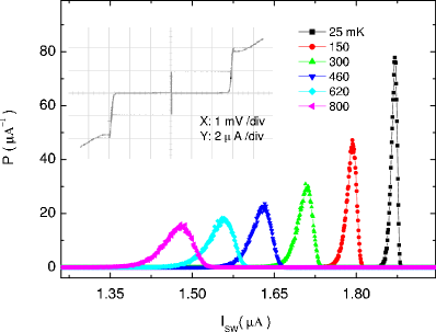
The sample used in this work was a dc SQUID containing two Nb/Al-AlOx/Nb junctions, which was prepared at Stony Brook using a self-aligned process. chen04 Each junction had a diameter of m (corresponding to an area of m2) and the SQUID loop had an area of m2. The device’s oscilloscope - trace at mK is displayed in the inset of Fig. 1. Taking A, we find the Josephson inductance of pH for each junction, which is much larger than the SQUID loop inductance of 30 pH. Hence, the SQUID can be viewed as a single junction having a maximum critical current .
According to the RCSJ model, rcsj the dynamics of a single junction biased at can be described by a fictitious phase particle with position , mass , and friction coefficient moving in a washboard potential
| (1) |
in which is the flux quantum, , and . and are the capacitance and shunt resistance of the junction, respectively. The plasma frequency of the junction is given by , where . For , the phase particle may escape from the potential well either by thermal activation (TA) or by macroscopic quantum tunneling, resulting in the junction’s switching from the zero to the finite voltage state. Crossover from MQT to TA is known to occur at , where , and is the quality factor. The escape rate in the TA regime can be found from Kramers’ formula: kram40
| (2) |
where is a damping dependent factor, and in the MQT regime from: cald81
| (3) |
where . In the above expressions, the barrier height is given by
| (4) |
We measured switching current distribution using the time-of-flight technique, as described in our previous works. li07 ; cui08 The results at some typical temperatures are shown in Fig. 1. In our experiment, the bias current was ramped up at a constant rate of =0.4 mA/s with a repetition rate of 97 Hz. To reduce statistical uncertainty each measured contained escape events. The sample was placed in a copper box, which was anchored to the mixing chamber (MXC) of an Oxford Kelvinox MX400 dilution refrigerator. To reduce the effects of external noise on switching dynamics to a negligible level, a trilayer -metal shield was used and the circuit was filtered by EMI filters at room temperature, cryogenic low-pass filters at 1 K pot, and copper powder microwave filters at MXC temperature. Since noise could cause temperature dependence of the width of to flatten out at , which could be mistaken as the evidence for MQT, we tested the noise level by applying a flux to the SQUID loop to reduce its critical current to The result confirmed that noise from the environment and measurement circuitry was negligible down to 25 mK. (The data presented in this work were however obtained with maximum critical current = in the absence of applied magnetic field. The plasma frequency at bias current 1.865 A, which is the position of maximum at 25 mK in Fig. 1, is 10 GHz.)
| Junction area | C | R | |
|---|---|---|---|
| 21.27 m2 | 1.957 A | 620 fF | 300 |
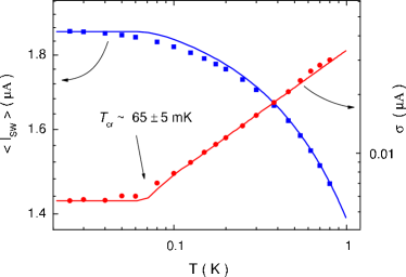
Fig. 1 shows that as temperature decreases, narrows and moves to higher bias current. In Fig. 2, we show the temperature dependence of the mean () and width () of (symbols), together with the results calculated from the TA and MQT theories (lines) using the standard conversion between and . fult74 From the fit, the sample’s parameters A, fF, and were obtained. rem In Fig. 2, we can see that in the temperature range between 1 K and mK, decreases with decreasing temperature indicating that TA is the dominant escape mechanism. In this temperature range, depends weakly on and , so can be determined by fitting using the TA theory starting with a reasonable estimate of and values. The values of and were then determined using obtained at because the exponent of MQT rate is dependent on and . In Table I, we summarize the sample’s key parameters. Taking the peak position at 25 mK in Fig. 1 again, we find that the crossover temperature calculated from these parameters is = 62.4 mK, which is in good agreement with the experimental value indicated in Fig. 2.
III Results with microwave radiation
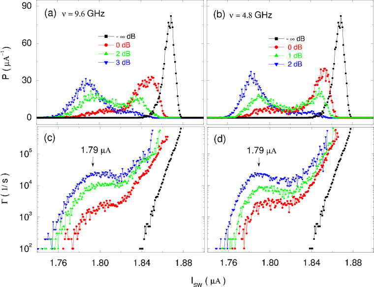
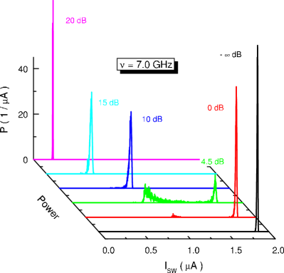
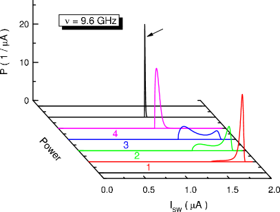
Fig. 3(a) shows the switching current distribution at mK in the microwave field with fixed frequency =9.6 GHz and four different power levels. (In this work, we always use relative power levels by normalizing to the power level at which the resonant peak first appears.) Fig. 3(c) shows the corresponding escape rate . It is seen that as increases, the primary peak of shifts to lower bias current and then a resonant peak develops. Further increasing causes the primary peak to disappear and resonant peak to grow into a single one (Results at higher are presented in Fig. 4 below). This result, though similar to situation (1) discussed in Section I, can be interpreted along a quantum-mechanical analysis by Fistul et al. fistul03 since the primary peak demonstrates a clear leftward shift resulting from effective barrier suppression. rem1
According to the discussion in Ref. fistul03, , the condition should be satisfied in order for the process described in situation (1) to occur. The physics behind this is that the microwave-induced excited-level population times the escape rate of the level should be large. Taking the junction’s parameters in Table I, we find and so the condition is clearly not satisfied. On the other hand, we calculated the energy levels, and the level escape and transition rates of the system using the approach described in Ref. kopi88, . The total escape rate was then obtained from the stationary solution of the Master equation as first considered by Larkin and Ovchinnikov. xu03 ; kopi88 ; lo86 We found that for the data without microwave radiation (- dB) in Figs. 3(a) and (c), there were three levels in the potential well and the calculated agreed well with the experimental result. If we assume an unsuppressed potential barrier in the microwave field and use =1.79 A at the resonant peak, we would have 6 energy levels in the well. In this case, even assuming all population at the first excited level would still lead to about 3 to 4 orders smaller than the measured escape rate. From these results, it is clear that a barrier suppression resulting in a reduction of one or two energy levels in the well is necessary to account for the experimental data in Fig. 3.
The calculated level spacing between the ground and first excited states at =1.79 A, which can also be estimated from , is 9.6 GHz, which exactly matches the frequency of the applied microwave. This result demonstrates that the quantum explanation of the resonant phase escape process is applicable. In Figs. 3(b) and (d), we show the corresponding results when the microwave frequency is reduced to GHz. Similar behavior can be seen, which is consistent with the quantum picture of the resonant phase escape as a result of the two-photon process. additional
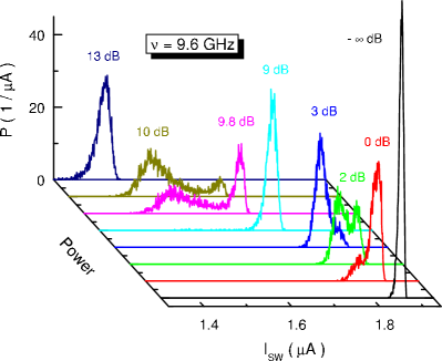
As increases, the primary peak in Fig. 3 decreases and eventually disappears while the resonant peak grows into a single one. The data taken at GHz are plotted in Fig. 4. The most interesting feature of the data in this figure is that a second resonant peak develops when is further increased. rem2 Compared with the previous case of weak microwave field, the separation between the second resonant peak and the first resonant peak is much larger than that between the first resonant peak and the primary peak. Furthermore, the separation is found to depend strongly on the microwave frequency . In Fig. 5, we show the dependence of at mK when is changed to GHz which is largely detuned from the level spacing GHz in the vicinity of the bias current where the primary peak is located. Therefore, resonant peak originated from PAT (e.g. the peaks just below the primary peak in Figs. 3 and 4) would not occur at low microwave power. As increases, the system gradually enters the strong driving regime. The primary peak is observed to shift leftwards continuously until a resonant peak at a much lower bias current A develops (note the different horizontal scales of Figs. 4 and 5). Such distinct results could originate from Josephson bifurcation, sidd05 ; manu07 a phenomenon common to strongly-driven nonlinear dynamic systems, as discussed below.
IV Discussion based on the classical nonlinear dynamics
It should be pointed out that the number of levels in the potential well at the second resonant peak (at A) in Fig. 4 and the corresponding peak at A in Fig. 5 would be about and over , respectively. The presence of so many energy levels during resonant escape, provided a dramatic barrier suppression did not occur, necessitates a many-photon process from the quantum mechanical point of view or motion with extremely large amplitude oscillations from the perspectives of classical dynamics. Since it is not clear whether the treatment of Fistul et al. fistul03 is applicable to such case we provide an explanation based on the classical description of dynamic bifurcation in nonlinear systems for the experimental results presented in Figs. 4 and 5. Our analysis shows that the experimental results obtained at high , namely the double-peak structure with large peak separation, can be caused by escape of the phase particle having very large oscillation amplitude resulting from bifurcation of the nonlinear system driven by strong microwave field. landau ; sidd05 ; manu07
IV.1 Nonlinear bifurcation phenomenon: Bistable oscillations with different amplitudes
We start with the normalized equation of motion for the phase particle:
| (5) |
where , , is the normalized ac current induced by microwave field, and is the microwave frequency normalized to . At low temperatures ( mK) and strong microwave field, the effect of noise current due to thermal fluctuations on escape rate is negligible and thus omitting in Eq. (5) is justified.
Following the analysis of Refs. jensen05, and fistul03, , we use a monochromatic ansatz for the solution of the unperturbed Eq. (5):
| (6) |
with
| (7) |
Inserting this ansatz into Eq. (5) and expanding and up to the third order yield: rem3
| (8) |
in which , , and . When the applied microwave frequency is close to the resonance, we can write , where / 1, and make the single-mode approximation:
| (9) |
where is a phase constant and is amplitude of the driven oscillation. Inserting this into Eq. (8), one obtains the following relation: landau
| (10) |
where .
From Eq. (10), the amplitude as a function of microwave power and bias current can be obtained since , and only depend on and/or when microwave frequency is constant. Thus, we have
| (11) |
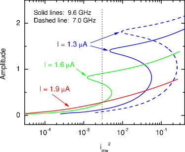
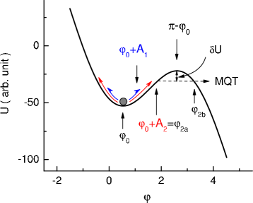
In Fig. 6, we present the calculated for three indicated bias current at GHz (solid lines) using the parameters listed in Table I. The results show clearly the familiar Josephson bifurcation phenomenon. sidd05 ; manu07 Namely, as increases, the system can be driven into a regime where two dynamic states with different amplitudes of oscillation exist, as shown schematically in Fig. 7. In Fig. 6, one can see that in the range of considered bifurcation does not occur at bias current A which is slightly below (. As decreases, it starts to develop. For lower bias current, threshold for bifurcation shifts to higher which is accompanied by a greater amplitude at the threshold while has a slow variation (the solid lines in Fig. 6). The dashed line in Fig. 6 is the result obtained using A and GHz. In this case, is significantly larger when compared to the case of same but higher driving frequency GHz. This result will be shown to be consistent with, and can be used to explain the changes from Fig. 4 to Fig. 5 when decreases.
IV.2 Resonant phase escape from bifurcated oscillation with the larger amplitude: Explanation for the results at = 9.6 GHz
We now show that the presence of resulting from bifurcation at high microwave power can qualitatively explain the double-peak structure with large peak separation as presented in Figs. 4 and 5. We first consider the four curves with relative power levels of 9, 9.8, 10, and 13 dB in Fig. 4 with applied microwave frequency GHz. In this case, all peaks are located at relatively high bias current, so from the results presented in Fig. 6, the maximum is seen to be around 1.5, which makes the approximation used in deriving Eq. (8) appropriate. rem3
Since our measurement was performed at mK, escape of the phase particle from the potential via thermal activation is negligible. Hence we consider a classical resonantly-oscillating particle and its MQT escape from the potential well. In general, the particle can escape from both and states, thus the MQT rate, in the absence of the barrier suppression, can be calculated using the WKB method from:
| (12) | |||||
where are the probabilities of the phase particle in the and states () and are the corresponding path integral across the remaining tunnel barriers. Because ( tunneling rate from the state is exponentially smaller and the escape is dominated by the latter. In an explicit form, we can write down the action for the phase particle in the state as:
| (13) |
in which is given by Eq. (1). The turning point at the outer wall of the potential , the point of escape , and the corresponding path of MQT, when the phase particle is in the state, are illustrated in Fig. 7.
For the present experimental data, we usually have a deep potential well [see Eq. (4), for bias current well below ] and the remaining barrier height (see Fig. 7) for the particle having oscillation amplitude is comparatively small. In this case, it is straightforward to show that Eq. (12) can be well approximated by
| (14) |
where is given by
| (15) |
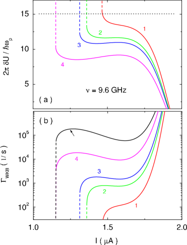
Various phase locations in Eq. (15) are indicated in Fig. 7. In Fig. 8(a), we show the tunneling exponent of Eq. (14) versus for GHz as is increased from curve to curve . Notice that for each curve there exists a nearly vertical part, shown as dashed lines, which corresponds to the sudden emergence of the state. This can be understood by considering the case for as indicated by the vertical dotted line in Fig. 6. At A, only the smaller amplitude state exists. The amplitude would increase as increases. At a bias current A A, the much larger amplitude state emerges which results in the sudden decrease of and thus a much larger tunneling rate. In Fig. 8(a), it can be seen that the curve 1 shows a monotonic dependence on . Starting from the curve 2, however, a local minimum develops. This behavior can in principle lead to the double-peak structure in as is increased.
To compare with which is the MQT rate in the absence of microwave radiation, we plot the exponent / in [see Eq. (3) considering 10] as a dotted line in Fig. 8(a), where corresponds to the position of the primary peak. Notice that the line sits well above the wide shoulder part of the solid curves resulting from the state of oscillation. Since tunneling rate depends exponentially on our data imply Namely, the particle spends more time in the state than in the state. rem4
In Fig. 8(b), we show calculated from Eq. (12) or (14) using and the same set of parameters as those in Fig. 8(a). The choice of around brings the escape rate for the system in the state of oscillation into the experimentally observable range of to sec-1 in Figs. 3(c) and (d), which is determined by the bias current sweeping rate of mA/s. It should be noticed that although the calculated bias current dependence of in Fig. 8(b) looks similar to the data presented in Figs. 3(c) and (d) as the microwave power increases, the non-monotonic part of covers a much larger range of bias current. Furthermore, unlike the data in Figs. 3(c) and (d), the hump feature in Fig. 8(b), which lead to the double peak moves much faster to lower currents with increasing microwave power. These distinct difference led us to conclude that the double peak distributions in Fig. 3 were originated from photon-assisted tunneling rather than the dynamic bifurcation under strong ac driving described above.
However, as the intensity of ac field is increased the dominant escape mechanism changes from PAT to Josephson bifurcation. Namely, the onset of state results in double-peak distributions with large inter-peak separation. In Fig. 9, the corresponding switching current distributions converted from the presented in Fig. 8(b) are plotted. The existence of the double-peak structure (curves labeled 2 and 3) can be clearly seen. Comparing the results with the experimental data in Fig. 4 (namely the curves with relative powers of 9, 9.8, 10, and 13 dB), we can see that the shapes of are quite similar and the applied power ratio between curve 4 and curve 1 is , also similar to the data displayed in Fig. 4.
IV.3 Results at = 7.0 GHz and further discussions
The results of 9.6 GHz microwave radiation suggest that the simple classical model provides a reasonably good qualitative explanation for the reappearance of the double-peak structure in Fig. 4 as ac driving is intensified. Such explanation is expected to work also for the data in Fig. 5 with 7-GHz microwave radiation. Unfortunately, analysis based on Eq. (8) does not work well for the GHz data since the resonant peak appears below A (see Fig. 5). In this case, we can see from the dashed line in Fig. 6 that becomes significantly greater than /2, which makes the expansion of the and terms in obtaining Eq. (8) inapplicable. rem3
Comparing the experimental results in Fig. 4 and Fig. 5, there are two clear changes of the bifurcation-induced resonant peaks as the microwave frequency decreases. One is the increase of the inter-peak separation of the double-peak distribution and the other is the rapid narrowing of the resonant peak width. The first change can be easily understood from Fig. 6 that for fixed bias current and power, is larger when is lower (compare the solid and dashed lines at A). This directly leads to the increase of the inter-peak separation for smaller . It is important to note that such trend is basically opposite to that reported in the previous work where is smaller and bifurcation is not involved. jensen04 ; jensen06
The rapid narrowing of the peak can also be explained by our model. To demonstrate this, we plot in Fig. 8(b) the result with = 9.4 GHz (the top curve indicated by the arrow), a value smaller than 9.6 GHz used in the figure but not far away so that the approximation used for Eq. (8) is still valid. We have raised slightly so that the vertical part of the curve sits at the same bias current as that of curve 4. We can see that the calculated increases quickly, roughly by one order of magnitude when is decreased only by 0.2 GHz. Such increase would influence the peak width significantly since, unlike the usual case such as those depicted in Figs. 3(c) and (d) where escape rate changes continuously, the bifurcation related escape rate versus dc bias current makes a sudden jump (dashed parts of the curves in the figure) when appears. While the rate of escape from the smaller amplitude oscillation is negligible, it increases rapidly when the oscillation appears, which results in switching to occur in a very small range of bias current and therefore a much narrower resonant peak. Apparently, the lower the is, the higher level the escape rate will suddenly jump to, and the narrower the resonant peak will be. The curve pointed by the arrow in Fig. 9 is the resulting distribution that appears considerably sharper than curve 4 in the same figure.
It should be pointed out that from our simple model the “primary” and “resonant” peaks in Fig. 9 have different meanings as conventionally understood from the data such as those in Fig. 3. According to the discussion on the results presented in Fig. 8, all peaks in Fig. 9 are caused by tunneling from the state of the resonantly driven phase particle. The double-peak structure is a result of combined effect of non-trivial bias current dependence of the potential well depth and the amplitude at a given . According to Eqs. (1) and (11), both quantities decrease as increases but at different rates. This gives rise to the local minima and humps in Fig. 8, and the “resonant” peak in Fig. 9.
We note that quantitatively the experimental data and calculation based on Josephson bifurcation do not agree well, thus further improvements of the model are necessary. Among them, including higher order terms in the expansion of and should be considered for in order to describe the data taken at GHz. rem3 We emphasize that Josephson bifurcation is used to explain the appearance of the second resonant peak in Fig. 4 for data taken at dB and dB. The double-peak structure at much weaker ac driving, from about dB to dB, is due to the quantum resonant phase escape process accompanied by barrier suppression, fistul03 ; fistul00 which is not considered in the present model.
V Summary
We presented a systematic study of resonant phase escape in tilted washboard potential of a Josephson junction (a dc SQUID with small loop inductance) at mK in the presence of strong ac driving (microwave radiation). The device was well-characterized using the TA and MQT theories in the absence of the microwave field. For weak ac driving , we observed results that are interpreted by quantum resonant escape of the phase involving single- and two-photon absorptions with a suppressed potential barrier. At larger , a second resonant peak, which is well separated from the first one, would appear. The peak could locate at very low bias current depending on the power and frequency of the microwave applied. We proposed a model based on the classical equation of motion to interpret the data. Our results indicated that at large , the phase particle enters a bistable state due to bifurcation of the nonlinear system and the oscillation state with larger amplitude leads to the resonant peaks in the switching current distributions locating far below the system’s critical current. These results are useful for the further studies of the nonlinear response of Josephson junctions to strong ac driving and for the detection of the qubit quantum states using a dc SQUID. In addition, the results and analysis showed that for junctions with strong ac driving, even at , the quantum-to-classical crossover temperature, escape of the phase particle could be dominated by classical processes. Our work therefore provides further evidence of the dual character, classical and quantum mechanical, of the Josephson junction system at in an ac driving field.
ACKNOWLEDGMENTS
We thank V. Patel, W. Chen, and J. E. Lukens for providing us with the Nb samples used in this work. The work at the Institute of Physics was supported by the National Natural Science Foundation of China (Grant Nos. 10534060 and 10874231) and the Ministry of Science and Technology of China (Grant Nos. 2006CB601007, 2006CB921107, and 2009CB929102). S. Han was supported in part by NSF Grant No. DMR-0325551.
References
- (1) Y. Makhlin, G. Schon, and A. Shnirman, Rev. Mod. Phys. 73, 357 (2001).
- (2) J. M. Martinis, M. H. Devoret, and J. Clarke, Phys. Rev. Lett 55, 1543 (1985).
- (3) J. Clarke, A. N. Cleland, M. H. Devoret, D. Esteve, and J. M. Martinis, Science 239, 992 (1988).
- (4) A. Wallraff, T. Duty, A. Lukashenko, and A. V. Ustinov, Phys. Rev. Lett. 90, 037003 (2003).
- (5) T. Bauch, T. Lindstrm, F. Tafuri, G. Rotoli, P. Delsing, T. Claeson, and F. Lombardi, Science 311, 57 (2006).
- (6) H. Xu, A. J. Berkley, M. A. Gubrud, R. C. Ramous, J. R. Anderson, C. J. lobb, and F. C. Wellstood, IEEE Trans. Appl. Supercond. 13, 956 (2003).
- (7) Y. Yu. S. Han, X. Chu, S. Chu, and Z. Wang, Science 296, 889 (2002).
- (8) J. M. Martinis, S. Nam, J. Aumentado, and C. Urbina, Phys. Rev. Lett. 89, 117901 (2002).
- (9) M. V. Fistul, A. Wallraff, and A. V. Ustinov, Phys. Rev. B 68, 060504(R) (2003).
- (10) M. V. Fistul, and A. V. Ustinov, Phys. Rev. B 63 , 024508 (2000).
- (11) Sun Guozhu, Wang Yiwen, Cao Junyu, Chen Jian, Ji Zhengming, Kang Lin, Xu Weiwei, Yu Yang, Han Siyuan, and Wu Peiheng, Phys. Rev. B 77, 104531 (2008).
- (12) M. H. Devoret, J. M. Martinis, D. Esteve, and J. Clarke, Phys. Rev. Lett. 53, 1260 (1984).
- (13) Bo Mao and Siyuan Han, IEEE Trans. Appl. Supercond. 17, 94 (2007).
- (14) T. Fonseca and P. Grigolini, Phys. Rev. A 33, 1122 (1986).
- (15) G. Rotoli, T. Bauch, T. Lindstrom, D. Stornaiuolo, F. Tafuri, and F. Lombardi, Phys. Rev. B 75, 144501 (2007).
- (16) N. Grnbech-Jensen and M. Cirillo, Phys. Rev. B 70, 214507 (2004).
- (17) N. Grnbech-Jensen, M. G. Castellano, F. Chiarello, M. Cirillo, C. Cosmelli, L. V. Filippenko, R. Russo, and G. Torrioli, Phys. Rev. Lett. 93, 107002 (2004).
- (18) N. Grnbech-Jensen, M. G. Castellano, F. Chiarello, M. Cirillo, C. Cosmelli, C. Cosmelli, V. Merlo, R. Russo, and G. Torrioli, in Quantum Computing: Solid State Systems, edited by B. Ruggiero, P. Delsing, C. Granata, Y. Paskin, and P. Silvestrini (Springer, New York, 2006) pp. 111-119.
- (19) N. Grnbech-Jensen and M. Cirillo, Phys. Rev. Lett. 95, 067001 (2005).
- (20) J. E. Marchese, M. Cirillo, and N. Grnbech-Jensen, Phys. Rev. B 73, 174507 (2006).
- (21) Frederick W. Strauch, S. K. Dutta, Hanhee Paik, T. A. Palomaki, K. Mitra, B. K. Cooper, R. M. Lewis, J. R. Anderson, A. J. Dragt, C. J. Lobb, and F. C. Wellstood, IEEE Trans. Appl. Supercond. 17, 105 (2007).
- (22) J. Claudon, A.Zazunov, F. W. J. Hekking, and O.Buisson, Phys. Rev. B 78, 184503 (2008).
- (23) J. Claudon, F. Balestro, F. W. J. Hekking, and O. Buisson, Phys. Rev. Lett. 93, 187003 (2004).
- (24) D. I. Schuster, A. Wallraff, A. Blais, L. Frunzio, R. Huang, J. Majer, S. M. Girvin, and R. J. Schoelkopf, Phys. Rev. Lett. 94, 123602 (2005).
- (25) L. D. Landau and E. M. Lifshitz, Mechanics (Pergamon press, New York, 1976).
- (26) I. Siddiqi, R. Vijay, F. Pierre, C. M. Wilson, L. Frunzio, M. Metcalfe, C. Rigetti, R. J. Schoelkopf, M. H. Devoret, D. Vion, and D. Esteve, Phys. Rev. Lett. 94, 027005 (2005).
- (27) V. E. Manucharyan, E. Boaknin, M. Metcalfe, R. Vijay, I. Siddiqi, and M. Devoret, Phys. Rev. B 76, 014524 (2007).
- (28) W. Chen, V. Patel, and J. E. Lukens, Microelectronic Engineering 73, 767 (2004).
- (29) W. C. Stewart, Appl. Phys. Lett. 12, 277 (1968); D. E. McCumber, J. Appl. Phys. 39, 3113 (1968).
- (30) H. A. Kramers, Physica (Utrechit) 7, 284 (1940).
- (31) A. O. Caldeira and A. J. Leggett, Phys. Rev. Lett. 46, 211 (1981).
- (32) Shao-Xiong Li, Wei Qiu, Siyuan Han, Y. F. Wei, X. B. Zhu, C. Z. Gu, S. P. Zhao, and H. B. Wang, Phys. Rev. Lett. 99, 037002 (2007).
- (33) D. J. Cui, H. F. Yu, Z. H. Peng, X. B. Zhu, Ye Tian, G. H. Chen, D. H. Lin, C. Z. Gu, D. N. Zheng, X. N. Jing, Li Lu, and S. P. Zhao, Supercond. Sci. Technol. 21, 125019 (2008).
- (34) T. A. Fulton and L. N. Dunkleberger, Phys. Rev. B 9, 4760 (1974).
- (35) was mainly contributed by a designed parallel capacitance in the device.
- (36) We point out that classical analysis should also work though quantum-mechanical approach is used here. See Refs. jensen04, , jensen06, , and sun08, for the resonant peak development and Refs. jensen04a, and jensen06, for the leftward shift of the primary peak.
- (37) P. Kopietz and S. Chakravarty, Phys. Rev. B 38, 97 (1988).
- (38) A. I. Larkin and Yu. N. Ovchinnikov, Zh. Eksp. Teor. Fiz. 91, 318 (1986) [Sov. Phys. JETP 64, 185 (1987)].
- (39) Resonant escape at 4.8 GHz involving two photons in Fig. 3(b) is expected to require a larger driving power than single photon escape at 9.6 GHz in (a). However, the power levels at the output port of the microwave generator were -37 dBm and -10 dBm for the two 0 dB curves in Fig. 3(b) and (a), respectively, due to the different attenuations at different frequencies of the measurement system. Our measurement showed that the loss along the coaxial line from microwave generator to sample box at 4.8 GHz was about 10 dB less than that at 9.6 GHz. Furthermore, microwave was coupled to the junction via an electrical dipole antenna. The coupling between the antenna and the junction was weak and strongly frequency dependent, so the final microwave power coupled to the junction for the two-photon process at 4.8 GHz was still larger than that for the single-photon process at 9.6 GHz. Similar results were observed, for example, in J. Lisenfeld, Probing quantum states of Josephson junctions by microwave fields, PhD thesis, Friedrich-Alexander-Universität Erlangen-Nürnberg, Germany (2003).
- (40) Heating effect induced by microwave field was negligible in our experiment. If we consider the ac current magnitude to be less than , the maximum heating power is about 0.6 nW. This value is much smaller than that generated by junction’s switching to the normal state ( 6 nW), which already shows negligible influence since the experimental agrees well with the theory.
- (41) Such expansion is strict as 0, and is reasonable when /2 1.5. From the results in Fig. 6, the treatment can be safely used for the 9.6 GHz data in Fig. 4, but can be inaccurate for those in Fig. 5 at lower microwave frequency.
- (42) In the corresponding quantum picture, a particle excited to an energy level near the barrier top by multi-photon process has a smaller probability to MQT out of the potential well than to decay into lower energy levels in the well.