Theory of Josephson transport through spintronics nano-structure
Abstract
We study the Josephson transport through ferromagnetic insulators (FIs) by taking into account its band structure explicitly. In the case of the fully polarized FIs (FPFIs), we found the formation of a -junction and an atomic-scale 0- transition induced by increasing the FI thickness. More remarkably, in the Josephson junction through spin-filter materials such as Eu chalcogenides, the orbital hybridization between the conduction and the localized electron gives rise to the -junction behavior. Such FI-based -junctions can be used to implement highly-coherent solid-state quantum bits.
keywords:
Josephson junction; Spintronics; Ferromagnetic insulator; Quantum bit1 Introduction
The developing field of superconducting spintronics subsumes many fascinating physical phenomena with potential applications that may complement non-superconducting spintronics devices [1]. In addition there is an increasing interest in the novel properties of junctions of superconductors and magnetic materials [2, 3]. One of the most interesting effects is the formation of a Josephson -junction in superconductor/ferromagnetic-metal/superconductor (S/FM/S) heterostructures [4, 5]. In the ground-state phase difference between two coupled superconductors is instead of 0 as in the ordinary 0-junctions. In terms of the Josephson relationship
| (1) |
where is the phase difference between the two superconductor layers, a transition from the 0 to states implies a change in sign of the critical current from positive to negative. Physically, such a sign change of is a consequence of a phase change in the pairing wave-function induced in the FM layer due to the proximity effect. The existence of the -junction in S/FM/S systems has been confirmed in experiment by Ryanzanov et al.[6] and Kontos et al.[7].
Recently, quiet qubits consisting of a superconducting loop with a S/FM/S -junction have been proposed [8, 9]. In quiet qubits, a quantum two-level system is spontaneously generated and therefore it is expected to be robust to the decoherence by the fluctuation of the external magnetic field. From the viewpoint of the quantum dissipation, however, S/FM/S junctions are inherently identical with S/N/S junctions (N is a normal nonmagnetic metal). Thus a gapless quasiparticle excitation in the FM layer is inevitable. This feature gives a strong dissipative or decoherence effect [10]. Therefore the realization of the -junction a interlayer is highly desired for qubit applications [11, 12, 13, 14].
In this paper, we investigate the Josephson effect through a ferromagnetic (FIs) numerically. Although the -junction formation in such junctions has been theoretically predicted [15] and subsequently analyzed by use of the quasiclassical Green’s function techniques [16, 17], a phenomenological -function potential have been used in order to model the FI barrier. Then a natural question to ask is can we realize the -junction in FIs? Moreover the possibility of the -junction formation in the FI-barrier case is also an interesting and unresolved problem. In order to resolve above issues, we will formulate a numerical method for the Josephson current through FIs by taking into account the band structure and the finite thickness of FIs explicitly [18]. Then we will show the possibility of the -junction formation for two important representative FIs in the spintronics field [19, 20], i.e., the fully polarized FI (FPFI) (e.g., La2BaCuO5) and the spin-filter materials (e.g., Eu chalcogenides).
2 Model
Let us consider a two-dimensional tight-binding lattice of the S/FI/S junctions as shown in Fig. 1(a). The vector
| (2) |
points to a lattice site, where and are unit vectors in the and directions, respectively. In the direction, we apply the periodic boundary condition for the number of lattice sites being . Electronic states in a superconductor are described by the mean-field Hamiltonian,
| (3) | |||||
Here
| (4) |
with
| (5) |
where () is the creation (annihilation) operator of an electron at with spin ( or ), means the transpose of , and is unit matrix. The chemical potential is set to be for superconductors. In superconductors, the hopping integral is considered among nearest neighbor sites and we choose
| (6) |
where is the amplitude of the pair potential in the -wave symmetry channel, and is a Pauli matrix.
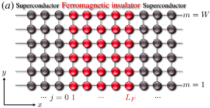
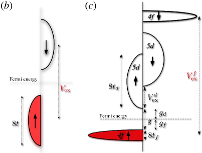
We consider two representative FIs as a barrier of the Josephson junction, i.e., FPFIs [Fig. 1(b)] and spin-filter materials [Fig. 1(c)]. The typical density of states (DOS) of FPFIs for each spin direction is shown schematically in Fig. 1(b). One of the important FPFIs is La2BaCuO5 (LBCO) [21, 22]. The exchange splitting is estimated to be 0.34 eV by a first-principle band calculation [23]. Since is large and the bands are originally half-filled, the system becomes FI.
The Hamiltonian of FPFI layer is described by a single-band tight-binding model as
| (7) | |||||
where is the exchange splitting [see Fig. 1(b)]. If (), this Hamiltonian describes FPFI (FM). The chemical potential is given by
| (8) |
Recently a spin-filter effect has been intensively studied for spintronics applications [19]. Typical spin-filter material is a Eu chalcogenide, e.g., EuO and EuS. The schematic DOS of the Eu chalcogenides is shown in Fig. 1(c). The Eu chalcogenides stand out among the FIs as ideal Heisenberg ferromagnets, with a high magnetic moment and a large exchange splitting of the conduction band for Eu -electrons. Ferromagnetic order of the spins causes exchange splitting of the conduction 5 band, lowering (raising) the spin-up (-down) band symmetrically by .
For the spin-filter materials such as Eu chalcogenides, we use a following - Hamiltonian including the - hybridization [24, 25],
| (9) |
Here
| (10) | |||||
| (11) | |||||
| (12) |
where ) is the creation operator, is the hopping integral and is the exchange splitting of electrons. The chemical potential of and electrons is respectively given by
| (13) | |||||
| (14) |
where is the energy gap of the band [see Fig. 1(c)]. The third term of the Hamiltonian describes the mixing between and electrons.
The Hamiltonian is diagonalized by the Bogoliubov transformation and the Bogoliubov-de Gennes equation is numerically solved by the recursive Green function method [26]. We calculate the Matsubara Green function in a FI layer,
| (15) |
where
| (16) |
is the Matsubara frequency. The Josephson current is given by
| (17) |
with being a temperature and . Throughout this paper we fix the following parameters: , and , , where is the superconductor transition temperature.
3 Josephson current through FPFI
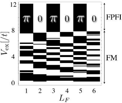
We first investigate the Josephson transport through FPFIs [Fig. 1(b)]. In the calculation, we assume for simplicity. The phase diagram depending on the strength of ( for FM and for FPFI) and is shown in Fig. 2. The black (white) regime corresponds to the - (0-)junction, i.e., . In the case of FPFI, the -junction can be formed. Moreover remarkably, the atomic-scale 0- transition is induced by increasing the thickness of the FI barrier . The physical origin of the 0- transition will be discussed in elsewhere [27].
4 Josephson current through spin-filter materials
Next we consider the Josephson transport through the spin-filter materials such as the Eu-chalcogenides. In the calculation, we use the following parameters in consideration of EuO: eV, eV, eV, and eV. For simplicity, we assume .
We first discuss the Josephson current through the -band only in order to check whether the spin-filter effect gives rise to the -junction behavior or not. In this case, we numerically found that no -junction is formed irrespective of the thickness and . Therefore the spin-filter effect gives rise to only the -junction behavior.
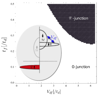
Next we consider the Josephson transport through the Eu-chalcogenides including both the and -band. In the calculation we set . We systematically change the values of the hopping integral for the band () and the - hybridization ). Fig. 3 shows the 0- phase diagram numerically obtained. Remarkably, the -junction is realized at the certain values of and . We found that the -junction can be formed if (1) and band for down spin are overlapped each other (see inset in Fig. 3) and (2) the - hybridization is strong enough. More detailed discussion for above results will be given in elsewhere [27].
5 Summary
To summarize, we have studied the Josephson effect in S/FI/S junction by use of the recursive Green’s function method. We found that the -junction and the atomic-scale 0- transition is realized in the case of FPFIs. On the other hand, in the case of the Josephson junction with the spin-filter material, the -junction can be formed if the and bands are overlapped and the - hybridization is strong. Such FI based -junctions can be used as an element in the architecture of ideal quiet qubits which possess both the quietness and the weak quasiparticle-dissipation nature. Therefore, ultimately, we could realize a FI-based highly-coherent quantum computer.
We would like to thank J. Arts, A. Brinkman, M. Fogelström, A. A. Golubov, P. J. Kelly, T. Löfwander, T. Nagahama, F. Nori, J. Pfeiffer, and M. Weides for useful discussions. This work was supported by CREST-JST, and a Grant-in-Aid for Scientific Research from the Ministry of Education, Science, Sports and Culture of Japan (Grant No. 19710085).
References
- [1] I. Zutic, J. Fabian, and S. D. Sarma, Rev. Mod. Phys. 76 (2004) 323.
- [2] A. A. Golubov, M. Y. Kupriyanov, and E. Il’ichev, Rev. Mod. Phys. 76 (2004) 411.
- [3] A. I. Buzdin, Rev. Mod. Phys. 77 (2005) 935.
- [4] L. N. Bulaevskii, V. V. Kuzii, and A. A. Sobyanin, JETP Lett. 25 (1977) 290.
- [5] A. I. Buzdin, L. N. Bulaevskii, and S. V. Panyukov, JETP Lett. 35 (1982) 178.
- [6] V. V. Ryazanov, V. A. Oboznov, A. Y. Rusanov, A. V. Veretennikov, A. A. Golubov, and J. Aarts, Phys. Rev. Lett. 86 (2001) 2427.
- [7] T. Kontos, M. Aprili, J. Lesueur, F. Genêt, B. Stephanidis, and R. Boursier, Phys. Rev. Lett. 89 (2002) 137007.
- [8] L. B. Ioffe, V. B. Geshkenbein, M. V. Feigel’man, A. L. Fauchére, and G. Blatter, Nature 398 (1999) 679.
- [9] G. Blatter, V. B. Geshkenbein, and L. B. Ioffe, Phys. Rev. B 63 (2001) 174511.
- [10] G. Schön, and A. D. Zaikin, Phys. Reports 198 (1990) 237.
- [11] S. Kawabata, S. Kashiwaya, Y. Asano, and Y. Tanaka, Physica C 437-438 (2006) 136.
- [12] S. Kawabata, S. Kashiwaya, Y. Asano, Y. Tanaka, and A. A. Golubov, Phys. Rev. B 74 (2006) 180502(R).
- [13] S. Kawabata, and A. A. Golubov, Physica E 40 (2007) 386.
- [14] S. Kawabata, Y. Asano, Y. Tanaka, S. Kashiwaya, and A. A. Golubov, Physica C 468 (2008) 701.
- [15] Y. Tanaka, and S. Kashiwaya, Physica C 274 (1997) 357.
- [16] M. Fogelström, Phys. Rev. B 62 (2000) 11812.
- [17] E. Zhao, T. Löfwander, and J. A. Sauls, Phys. Rev. B 70 (2004) 134510.
- [18] S. Kawabata, Y. Asano, Int. J. Mod. Phys. B 23 (2009) 4320.
- [19] J. S. Moodera, T. S. Santos, and T. Nagahama, J. Phys. Cond. Mat. 19 (2007) 165202.
- [20] C. Felser, G. H. Fecher, and B. Balke, Angrew. Chem. Int. Ed. 46 (2007) 668.
- [21] F. Mizuno, H. Masuda, I. Hirabayashi, S. Tanaka, M. Hasegawa, and U. Mizutani, Nature 345 (1990) 788.
- [22] W. Ku, H. Rosner, W. E, Pickett, and R. T. Scalettar, Phys. Rev. Lett. 89 (2002) 167204.
- [23] V. Eyert, K. H. Höc, and P. S. Riseborough, Europhys. Lett. 31 (1995) 385.
- [24] W. Nolting, Phys. Stat. Sol. (b) 96 (1979) 11.
- [25] W. Nolting and A. Ramakanth, Phys. Rev. B 33 (1986) 1838.
- [26] Y. Asano, Phys. Rev. B 63, 052512 (2001).
- [27] S. Kawabata, Y. Asano, Y. Tanaka, A. A. Golubov, S. Kashiwaya, Phys. Rev. Lett. 104, 117002 (2010).