A simple design of an artificial electromagnetic black hole
Abstract
We study the properties of an artificial electromagnetic black hole for transverse magnetic modes rigorously. A multi-layered structure of such a black hole is then proposed as a reduced variety for easy experimental realizations. An actual design of composite materials based on the effective medium theory is given eventually with only five kinds of real isotropic materials. The finite element method confirms the functionality of such a simple design.
pacs:
I Introduction
Transformation optics ulf ; pen is a useful tool to design many novel wave manipulation devices sch ; liu ; tre ; val ; gab ; smo ; chen ; mei ; ma . Its general form, the “general relativity in electrical engineering” njp , was proposed to mimic cosmic optical properties miao ; chy . A further method was also suggested gen , which can transmute the anisotropic parameters from the general form into isotropic ones. An isotropic “optical black hole” was given as well based on such a transmuting method gen . Another approach to a broadband absorber was also proposed from Hamiltonian optics apl . Such an absorber can be termed as an effective ‘optical black hole” apl , which was later implemented by using nonresonant metamaterial units in microwave frequencies for transverse electric(TE) modes cui . The experiment demonstrated the importance of metamaterials in implementing the related transformation media devices once again. However, the structure is a bit complicated and will be very challenging to adapt for higher frequencies.
In this paper, we will consider the transverse magnetic(TM) modes of such an artificial electromagnetic(EM) black hole cui and give a simple design with several kinds of real materials. In the following, we begin with the rigorous studies of TM modes of such an EM black hole in section 2. Then we propose a simple design based on composite materials in section 3. Finally, we give conclusions in section 4.
II The rigorous calculations of an artificial black hole for TM modes
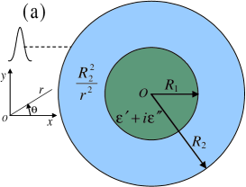
We start from the same permittivity profile of the artificial EM black hole as in Ref. apl ,
| (1) |
where with the geometry parameters described in Fig.1(a).
As it is mentioned in Ref. apl , the TE and TM polarizations decouple and can be solved independently. The TE EM black hole has been studied rigorously apl and implemented with nonresonant metamaterial units cui . With similar procedures, we will focus on the TM modes with the magnetic field along the -direction and propose a much simpler design in the following sections.
In the region , the general solutions of the magnetic field in -direction can be written as JMO ; semiclassical theory1 ,
| (2) |
where is the angular momentum number, is the angular frequency, and satisfies,
| (3) |
whose solutions can be expressed as
| (4) | |||
with the wave vector of light in vacuum .
In the region , we suppose that an Gaussian beam is incident with its magnetic field in -direction semiclassical theory1 ; wu and guo ,
| (5) |
where are Bessel functions of order , and is determined by semiclassical theory1 ; wu and guo ,
| (6) | |||
where is the wavelength of the Gaussian beam, is half of the beam waist, is beam center in Cartesian coordinates, and is the angle between the wave vector and -axis. The scattering waves are assumed to be,
| (7) |
where are the first kind Hankel functions with the angular momentum number . Hence the total magnetic field is the summation of the incident field and the scattering field ,
| (8) | |||
In the region , the absorbing core is isotropic with permittivity , the magnetic field in -direction can be written as,
| (9) |
From the continuous conditions on the boundaries and , i.e., the continuities of the magnetic field in -direction and its normal derivative, the coefficients , , , and can be uniquely determined in terms of the incident coefficients .
In this paper, we will set , , , inabs , and for instance. The waist of the incident Gaussian beam is and the beam center is at . We use a cut-off angular momentum number during the calculations. The magnetic field intensity pattern is plotted in Fig.1(b), which shows that the beam is bent enormously toward and absorbed by the inner core. Thereby the above absorbing system can be termed as an “EM black hole” apl .
The absorption cross section per unit length can be written as bohren ,
| (10) |
with . Substituting the above parameters, the absorption cross section of the present artificial black hole is 0.2231, which is close to its geometry cross section bohren . That means this artificial black hole can sever as a nearly perfect absorber as in Ref. apl .
III Two-step approach to a simpler design of an EM black hole, a layered structure and an actual design
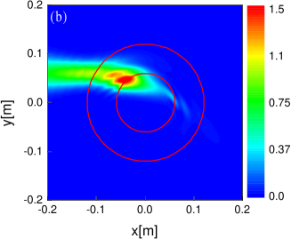
The above artificial black hole can be designed by using multi-layered cylindrical structureJMO . We break up the inhomogeneous region into concentric shells of isotropic dielectrics with equal thickness. In Fig.2(a), we plot the relationship between the layer number in and the absorption cross section, which is calculated by generalized Mie theory (GMT) for multi-layered structure and Eq. (10). The results show that a twelve-layer structure is good enough to implement such an EM black hole. As a concrete example, we will use 12 layers of isotropic materials whose relative permittivities are shown in Fig.2(b). The outmost layer is set to be air while the permittivity of the inner absorbing core is inabs . Fig.2(c) shows the magnetic field intensity pattern near the present layered structure black hole based on GMT. The related absorption cross section is about 0.2222, which means that the layered structure works as well as the original one.
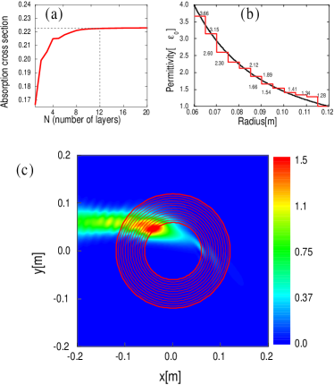
However, it would be difficult to find the above twelve layers of isotropic materials one by one. Based on a two-step approach PRL2 , we will implement this layered EM black hole with only five kinds of real isotropic materials. We will use the following real materials, air, aluminum (Al) metal rods, polyethylene (PE), polymethyl methacrylate (PMMA) plexiglass, and Polyvinylidene fluoride (PVDF). Their related permittivities in microwave frequencies (near 10 GHz) are about , , and book (Note that and chen ). As the equal thickness of each layer is , we divide each layer into cells each measuring in the middle so that each cell has “fanlike” shape chen . A cylinder with one kind of materials is placed in the center of each cell and embedded in a background material. Because the thickness of each cell/layer is very small when compared with the wavelength, we can approximate the above twelve layers of isotropic materials with composite materials of the above five kinds of materials based on the effective medium theory (EMT) hu ; jensen ; junfeng . Each layer of isotropic materials can be approximated by a circular array of cylinders embedded in a background material, see for details in Fig.3(a). From the EMT, the effective permittivity of composite materials with cylinders embedded in a background material with square lattice satisfies,
| (11) |
where is the permittivity of the background material while is the permittivity of cylinders with square lattice, and is the filling ratio of the cylinders. Suppose the lattice constant is , with the radii of cylinders .
As the permittivities of the outer nine layers are in the range of 1 and 2.3, we can use air-PE composite materials to approximate each layer. We shall embed air hole cylinders in PE to approximate the permittivities from 1.28 to 2.12 (seven layers). The radii of cylinders in each layer can be obtained from Eq. (11) (from to , see also in Fig.3(a), the PE is denoted with green color while the air hole cylinders are denoted with blue color). As permittivities of the inner three layers in is 3.66, 3.15 and 2.6, we can use Al-PMMA composite materials to approximate two of them. As the effective permeability of such composite materials is not unity hu , we shall use the square of the effective refractive index (but not the effective permittivity) to approximate the above two permittivities (3.66 and 3.15), i.e.,
| (12) |
Likewise, we can obtain the radii of Al cylinders ( and from Eq. (12), see also in Fig.3(a), the PMMA is denoted with orange color while the Al cylinders are denoted with dark blue color). The inner absorbing core can be approximated by using air hole cylinders embedded in PVDF. The inner core is also divided into twelve layers with the same procedure as that applied to the region . The radii of the air hole cylinders are from Eq. (11) (see also in Fig.3(a), the PVDF is denoted with brown color while the air hole cylinders are denoted with blue color).
Figure 3(b) shows the magnetic field intensity pattern near the black hole designed above in Fig.3(a). We use COMSOL Multiphysics finite element-based electromagnetics solver to perform the simulation, which shows that the black hole with the above composite materials can approximate both the layered structure black hole and the original EM black hole very well. In addition, we found in Fig.3(c) that if we replace the inner core by using PVDF solely (without embedding the air holes), the device still functions. Hence these two designs both serve for easy experimental fabrication of EM black holes.
IV conclusion
To summarize, we have rigorously studied the properties of an EM black hole for TM modes. With a two-step approach, we proposed actual designs of such a black hole by using composite materials with only five kinds of real isotropic materials, enabling easy fabrications with nowadays technologies. Our design circumvents retrieving specific constitute parameters from resonant structures, the device is expected to function in a broad bandwidth of frequencies. In particular, due to the simplicities of such designs, it would be feasible to adapt the same method for higher frequencies, such as THz, infrared, or even optical frequencies val ; gab .
Acknowledgements.
This work was supported by the Soochow University Start-up grant No. Q4108909, the China 973 program, NNSFC, PCSIRT, MOE of China (B06011), and the Shanghai Science and Technology Commission. We thank Dr. Junjie Du, Dr. Zhihong Hang, and Prof. Qiang Cheng for helpful discussions.References
- (1) U. Leonhardt, Science 312, 1777-1780 (2006).
- (2) J. B. Pendry, D. Schurig, and D. R. Smith, Science 312, 1780-1782 (2006).
- (3) D. Schurig, J. J. Mock, B. J. Justice, S. A. Cummer, J. B. Pendry, A. F. Starr, and D. R. Smith, Science 314, 977-980 (2006).
- (4) R. Liu, C. Ji, J. J. Mock, J. Y. Chin, T. J. Cui, D. R. Smith, Science 323, 366-369 (2009).
- (5) S. Tretyakov, P. Alitalo, O. Luukkonen, and C. Simovski, Phys. Rev. Lett. 103, 103905 (2009).
- (6) J. Valentine, J. Li, T. Zentgraf, G. Bartal, and X. Zhang, Nature Mater. 8, 568-571 (2009).
- (7) L. H. Gabrielli, J. Cardenas, C. B. Poitras, and M. Lipson, Nature Photonics 3, 461-463 (2009).
- (8) I. I. Smolyaninov, V. N. Smolyaninova, A. V. Kildishev, and V. M. Shalaev, Phys. Rev. Lett. 102, 213901 (2009).
- (9) H. Y. Chen, B. Hou, S. Chen, X. Ao, W. Wen, and C. T. Chan, Phys. Rev. Lett. 102, 183903 (2009).
- (10) Z. L. Mei and T. J. Cui, Opt. Express 17, 18354-18363 (2009).
- (11) Y. G. Ma, C. K. Ong, T. Tyc, and U. Leonhardt, Nature Mater. 8, 639-642 (2009).
- (12) U. Leonhardt and T. G. Philbin, New J. Phys. 8, 247 (2006).
- (13) M. Li, R.-X. Miao, and Y. Pang, arXiv: 0910.3375.
- (14) H. Y. Chen, R.-X. Miao, and M. Li, arXiv: 0912.4856.
- (15) D. A. Genov, S. Zhang, and X. Zhang, Nature Phys. 5, 687-692 (2009).
- (16) E. E. Narimanov and A. V. Kildishev, Appl. Phys. Lett. 95, 041106 (2009).
- (17) Q. Cheng and T. J. Cui, arXiv: 0910.2159.
- (18) M. A. Kaliteevski, R. A. Abram. V. V. Nikolaev, and G. S. Sololovski, J. Mod. Opt. 46(5), 875-890 (1999).
- (19) Z. Jacob, L. V. Alekseyev, and E. Narimanov, J. Opt. Soc. Am. A 24, A52 (2007).
- (20) E. Zimmermann, R. Dandliker, and N. Souli, J. Opt. Soc. A 12, 398-403 (1995).
- (21) We used as an example because we found that such an absorbing material can be implemented with composite materials of air hole cylinders embedded in Polyvinylidene fluoride (PVDF) as background material. One can use other values of if some other kinds of absorbing materials are reqiured.
- (22) C. F. Bohren and D. R. Huffman, Absorption and Scattering of Light by Small Particles (John Wiley and Sons Inc., 1983).
- (23) A. I. Cbuz, D. Felbacq, and D. Cassagne, Phys. Rev. Lett. 98, 037403 (2007).
- (24) D. M. Pozar, Microwave engineering (Third edition, John Wiley and Sons Inc., 2005).
- (25) X. H. Hu, C. T. Chan, J. Zi, M. Li, and K.-M. Ho, Phys. Rev. Lett. 96, 223901 (2006).
- (26) Y. Wu, J. Li, Z.-Q. Zhang, and C. T. Chan, Phys. Rev. B 74, 085111 (2006).
- (27) J. F. Jin, S. Y. Liu, Z. F. Lin, ans S. T. Chui, Phys. Rev. B 80, 115101 (2009).