Controlling Half-metallicity of Graphene Nanoribbons by Using a Ferroelectric Polymer
Abstract
On the basis of first-principles computational approaches, we present a new method to drive zigzag graphene nanoribons (ZGNRs) into the half-metallic state using a ferroelectric material, poly(vinylidene fluoride) (PVDF). Owing to strong dipole moments of PVDFs, the ground state of the ZGNR becomes half-metallic when a critical coverage of PVDFs is achieved on the ZGNR. Since ferroelectric polymers are physisorbed, the direction of the dipole field in PVDFs can be rotated by relatively small external electric fields, and the switching between half-metallic and insulating states may be achieved. Our results suggest that, without excessively large external gate electric fields, half-metallic states of ZGNRs are realizable through the deposition of ferroelectric polymers and their electronic and magnetic properties are controllable via noninvasive mutual interactions.
Since graphene, a single layer of graphite, was shown to be exfoliated on the silicon oxide surface Novoselov et al. (2004), there has been many studies on its various interesting physical, chemical, and mechanical properties. Specially, its unique electronic characteristics have spurred researchers to envisage nanoelectronic circuits composed of carbon atoms only Berger et al. (2006); Geim and Novoselov (2007). To achieve nanoelectronic devices based on graphene, it should be cut into small pieces which inevitably have edges at the boundaries. Together with the finite size effects Fujita et al. (1996); Nakada et al. (1996), nanoscale graphene fragments with these edges exhibit many different properties compared with those of two-dimensional graphene. Thus, it is important to understand the physics of the one-dimensional graphene nanostructure, that is, graphene nanoribbon (GNR) Fujita et al. (1996); Nakada et al. (1996). Among various properties of the ribbon studied Son et al. (2006a); Han et al. (2007); Chen et al. (2007); Li et al. (2008a); Wang et al. (2008); Son et al. (2006b); Lee et al. (2005); Jung et al. (2009), the magnetism of the zigzag graphene nanoribbon (ZGNR) is especially notable Son et al. (2006b); Lee et al. (2005); Jung et al. (2009). The magnetism arises at the zigzag-shaped edges because of the localized -orbitals of carbon atoms at the edges Fujita et al. (1996); Son et al. (2006b); Lee et al. (2005); Jung et al. (2009). Considering a quite long spin coherence length in graphene Tombros et al. (2007), the magnetism at the edges may be useful in future spintronics applications Wolf et al. (2001).
One of the most interesting properties regarding the application of the magnetism in ZGNRs Hod et al. (2008); Hod and Scuseria (2008); Hod et al. (2007); Cervantes-Sodi et al. (2008); Li et al. (2008b); Kan et al. (2008); Zheng et al. (2008) is the electric-field-induced half-metallicity Son et al. (2006b). Under the transverse electric field, ZGNRs show the half-metallicity Son et al. (2006b) which originates from a unique interplay between the interedge antiferromagnetic ordering and the relative potential shift between two edges. Despite its novel feature, the required transverse electric field for the half-metallicity is too strong to be obtained easily in experiments Son et al. (2006b). Many researchers have suggested diverse methods, such as introducing quantum dots with the zigzag edges Hod et al. (2008); Hod and Scuseria (2008), functionalizing edges of ZGNRs Hod et al. (2007); Cervantes-Sodi et al. (2008); Li et al. (2008b), and boron-nitrogen (B-N) substituting for designated carbon atoms Kan et al. (2008); Zheng et al. (2008). Some of these methods are successful in showing half-metallicity without external electric fields, though impractical because fine control of positions of functional groups and B-N substitution is inevitable. Moreover, the half-metallic states are hardly controllable with those proposed methods.
In this paper, we propose a method to drive the ZGNR into a half-metallic state by depositing a ferroelectric material, poly(vinylidene fluoride) (PVDF) Bune et al. (1998) on the ZGNR. The PVDF, one of the well-known ferroelectric materials, shows strong ferroelectricity and high crystallinity Malin et al. (2007); Naber et al. (2005); Hu et al. (2009); Lovinger (1983).
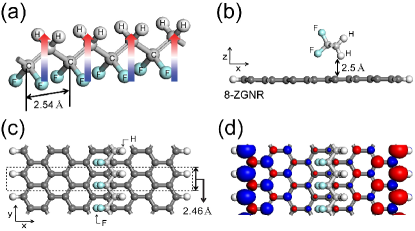
The atomic model for the PVDF is in Figure 1a. In general, two surfaces of the ferroelectric thin film, cut across the dipole moment aligned to a certain direction, cause a potential difference due to the dipole field. Likewise, several aligned PVDFs form the electric field which is induced by the dipole moments, and even a few layers show a substantial ferroelectricity. Here, we show that PVDFs can weakly bind to the surface of the ZGNR, with dipole direction parallel to the surface, thereby achieving the half-metallicity without any electric field. Because of their weak binding nature, the direction of induced electric fields is controllable, and the switching between half-metallic states and antiferromagnetic insulating states are made possible by external gate fields. We also note other experiment studies exploiting the interplay beetween ferroelectricity of the PVDF and graphene Zheng et al. (2009); Ansari and Giannelis (2009).
Results and Discussion
We have considered the -ZGNR that has units of the C-C pair in the -direction per unit cell and repeats along the -axis with the periodicity of 2.46 Å. The unit cell of the PVDF also repeats along the -axis, but with a different equilibrium unit cell length of 2.54 Å which is 3.15% longer than that of the ZGNR (Figure 1a). For convenience, the unit cell size of the PVDF is set to be reduced in the -direction so that it matches the length of the ZGNR (2.46 Å) in studying the joint system (Figure 1b,c). The unit cell in this system is indicated in Figure 1c. We confirm that our atomic models with the slightly compressed PVDF on the ZGNR give essentially the same results as the ones obtained from a fully relaxed geometry (without compression) in a very large commensurate unit-cell for the PVDF and the ZGNR. We will discuss this issue later. The vacuum along the -axis is set to be longer than 70 Å in order to avoid the spurious dipole interactions between the adjacent PVDFs in repeated supercells. All properties remain the same when the supercell size is doubled, and the dipole correction is negligible for our purpose. In determining the most stable position of the PVDF on the ZGNR, three parameters have to be optimized simultaneously: directions of the dipole moment of the PVDF, heights of the PVDF from the ZGNR plane, and distances between the PVDF and the edge of the ZGNR along the -axis. From a combinatorial search, the structure is found to be stabilized when the dipole orientation is parallel to the surface of the ZGNR, the height of the lowest atom of the PVDF from the ZGNR is 2.5 Å, and the PVDF lies on the middle position of the ZGNR (Figure 1b,c).
From theoretical Duan et al. (2004) and experimental Bune et al. (1998); Noda et al. (1999, 2000); Choi et al. (2000) studies, the dipole orientation of the PVDF is known to depend highly on the kind of substrate. When the substrate is a conductor, the image dipole is induced by the dipole of the PVDF on conducting substrates and the interaction energy between two dipoles should be taken into account. If we regard the PVDF as a single dipole, the energy of perpendicular dipoles is from the dipole-dipole interaction energy equation Duan et al. (2004), where and denote the magnitude of the dipole moment and the distance between the dipole of the PVDF and its image dipole, respectively. On the other hand, the energy of parallel dipoles is . Thus, on the conducting substrate, the perpendicular dipole direction of the PVDF is energetically favored Duan et al. (2004); Choi et al. (2000). On the contrary, in the case of an insulating or semiconducting substrate, for example, KBr Noda et al. (2000) or KCl Noda et al. (1999), the dipole is aligned parallel to the surface plane because the image dipole is negligible Duan et al. (2004). From the calculations, we find that the PVDF favors lying flat to the ZGNR plane since the ZGNR is semiconducting with its low screening capability.
The distance from the ZGNR to the lowest atom of the PVDF is found to be 2.5 Å, and it is 3.5 Å from the ZGNR to the C-C bond of the PVDF (Figure 1b). From the fully relaxed geometries, we can infer that the PVDF weakly binds to the ZGNR and the PVDF affects the electronic structure of the ZGNR not through chemical bonding between the PVDF and the ZGNR, but through the electronic potential induced by the strong dipole moment. The structure shown in Figure 1c, where the C-C bonds of the PVDF and those of the ZGNR cross each other at the middle of the ZGNR, has been found to a ground state. Even if the PVDF deviates its ground state geometry slightly, we find that no essential variation occurs in the electronic structures due to the weak bonding between the PVDF and the ZGNR. It is also noticeable that, with the PVDF, the antiferromagnetic spin configuration of the ZGNR is still more stable than the ferromagnetic one. For a single PVDF on the 8-ZGNR, the interedge antiferromagnetic ordering is more stable by 2.1 meV per edge atom. The isosurface of the charge density difference between the up-spin and the down-spin () in this case is presented in Figure 1d.
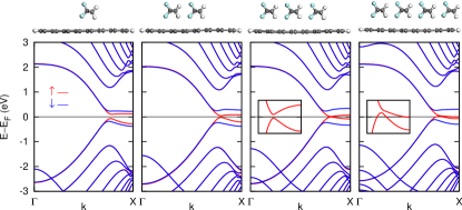
Now, we analyze the band structure of this joint system, a single PVDF on the 8-ZGNR. The pristine 8-ZGNR shows a small band gap of 0.3 eV for both spins. With one PVDF deposited on the 8-ZGNR, the band structure of the ZGNR is changed as if it were under external transverse electric fields Son et al. (2006b) (Figure 2). The electric potential energy is raised at the fluorine side and lowered at the hydrogen side of the PVDF. Since the dipole field decays slowly in space, the potential drop induced by this dipole field takes place over a large area which can cover both edges of the ZGNR. The energy eigenvalues of the ZGNR are also modified by this potential variation so that the band gap of the, say, up-spin state is reduced to 0.18 eV, and that of the down-spin state is increased up to 0.41 eV (Figure 2). We can estimate the potential profile generated by a single PVDF chain on the ZGNR by averaging the potential energies in the -axis with the position of the ZGNR fixed in direction. Its drop across two edges of the PVDF is 1.2 V and that of the 8-ZGNR is 0.8 V. According to previous works Son et al. (2006b), such a band gap change corresponds to the case of homogeneous electric field of 0.05 V/Å applied to the 8-ZGNR, that is, the total potential difference between two edges of the 8-ZGNR is 0.89 V ( = 0.05 V/Å 17.85 Å, where 17.85 Å is the length of the 8-ZGNR), which agrees reasonably well with the present calculation of 0.8 eV. Thus, the change of the bandgap mainly originates from the potential difference between two edges of the ZGNR. When the electric field is applied, the energy eigenvalues of the states localized on the left side of ZGNRs are pulled up, and those on the right side are pushed down Son et al. (2006b). Then, the energy gap of the up-spin state decreases, and that of the down-spin increases. We conclude that the energy eigenvalues of ZGNRs are modified because of interplay between the antiferromagnetic interedge ordering and the dipole field of the PVDF.
Before proceeding further, we check the lattice mismatch problem between the PVDF and the ZGNR in the unit cell. As we mentioned before, the lattice of the PVDF is reduced to that of the ZGNR in the -axis. To verify the effect of the compressed PVDF on the ZGNR, same calculations are performed for a large supercell amounting to 32 unit-cells of the ZGNR and 31 unit-cells of the PVDF, in which the bonds experience almost no strain. Very little change of the band structure is observed with a different width of the PVDF along the periodic direction. Hence, the role of the PVDF is only to generate the electric field by its dipole moment, and the position of the PVDF or the reduced cell size does not appreciably influence the electronic and magnetic properties of the system. In addition, a typical domain size of the ferroelectric thin film of the PVDF is around 200 nm so that, if considering a nanoscale channel device geometry, the effect of phase changes along the PVDF would not be serious in the present case. Ducharme et al. (2005)
Next, we increase the number of PVDFs deposited on the 8-ZGNR one by one (Figure 2). Dipole moments of PVDFs are all aligned in the same direction. The total dipole moment of PVDFs is increased, and the potential drop across the ZGNR becomes 1.26, 2.0, and 3.0 V if the number of PVDFs is 2, 3, and 4, respectively, in the 8-ZGNR case. (The local potential drop between two edges of PVDFs increases to 2.1, 3.4, and 5.0 V as increasing the number of PVDFs.) The band gap of the up-spin state is decreased while that of the down-spin state increases as the number of PVDFs increase. Eventually, if four PVDFs are coated on the 8-ZGNR, the system turns to a half-metal. The up-spin states cross the Fermi level while the down-spin states still have a band gap of 0.37 eV. Four PVDFs generate enough of a potential difference (3.0 eV) between two edges of the ZGNR to give rise to the half-metallicity of the ZGNR. With low defect concentrations at the edges, the half-metallic nature of ZGNRs is already shown to be robust under the applied external transverse electric field in the previous work. Son et al. (2006b) Since PVDFs here play the same role as do external fields in ref 11, we note that the induced half-metallicity of the ZGNRs will occur as long as weak edge defects or imperfections do not alter the magnetic ordering at the edges.
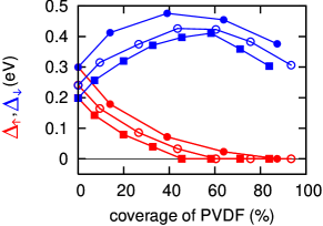
Our calculations indicate that four PVDFs create a potential drop of 3.0 V across the -ZGNR irrespective of the width ( value) of ZGNRs (for 8, tested up to = 32). The -ZGNR becomes half-metallic when the potential drop across the system generated by PVDFs reaches 3.0 V, which has been suggested to be the critical value for half-metallicity in the previous work Son et al. (2006b). In terms of the percentage coverage (i.e., the area of covered PVDFs divided by the area of the ZGNR), the critical value for the transition to half-metal can be calculated by the width of four PVDFs (16.0 Å) divided by the width of the ZGNR (), ( is in angstrom). This can be regarded as a scaling behavior in the PVDF coverage and the width of ZGNRs as follows, similar to the previous study on scaling in the strength of transverse electric fields and the width of the ZGNR Son et al. (2006b) (Figure 3).
Finally, another advantage of our proposal compared with others lies in the fact that the half-metallic state can return to the insulating state by changing of the dipole orientation of PVDFs. If the dipole direction of PVDFs is set perpendicular to the ZGNR plane by a perpendicular external electric field as in the usual experiments with back gates, then the potential drop across the ZGNR vanishes and the half-metallicity disappears as well. We have calculated variations of the total energy by rotating a single PVDF on ZGNRs. We have found that, without a perpendicular electric field, the perpendicular dipole direction of the PVDF to the ZGNR is also at the local energy minimum (or quasi-stable configuration), 30 meV higher than the ground state (the parallel dipole direction). Upon application of perpendicular electric fields, the energy differences between parallel and perpendicular dipole configurations are decreased and eventually, with an electric field of 0.07 V/Å, the perpendicular dipole direction becomes the ground state. An energy barrier for rotation of the PVDF on the ZGNR, that is, parallel to perpendicular direction change, is 96 meV per unit cell without an electric field and decreases to 77 meV with an electric field of 0.07 V/Å. Therefore, it is practically possible to switch between half-metallic and insulating states by applying a perpendicular gate field greater than 0.07 V/Å.
Conclusion
We have proposed a method to construct the half-metallic ZGNRs by depositing the ferroelectric material PVDFs on them. The PVDFs generate the electrostatic potential on the ZGNR because of their strong dipole moments. When the number of PVDFs coated on ZGNRs increases beyond a critical value, the system becomes be half-metallic. The dipole direction of PVDFs is changeable by an external electric field, and switching between half-metallic and insulating states in ZGNRs is made possible.
Theoretical Methods
We performed the first-principle calculations based on the density-functional theory (DFT) within the local spin density approximation (LSDA) Soler et al. (2002) and spin polarized general gradient approximation (GGA) with the Perdew-Burke-Ernzerhof (PBE) functional Perdew et al. (1996), respectively, by using the SIESTA package Soler et al. (2002). The standard norm-conserving Troullier-Martins pseudopotentials Troullier and Martins (1991) were employed, and split-valence double- plus polarization basis Soler et al. (2002) was used. We have chosen a 400 Ry energy cutoff for a real space mesh size and 96 -points, uniformly distributed in the 1D Brillouin zone. All edges were saturated with hydrogen atoms and relaxed by conjugate gradient minimization until the maximum force was less than 0.04 eV/Å. To overcome an intrinsic error due to the pseudoatomic orbital basis set in the weakly binding system, the basis set superposition error (BSSE) was corrected using a counterpoise procedure Boys and Bernadi (1970); Stone (1996). In calculations with the PBE functional, we added a pairwise interatomic term () to the PBE-DFT energy in order to include the van der Waals (vdW) interaction Grimme (2006); Barone et al. (2008); Tkatchenko and Scheffler (2009). To obtain accurate vdW energies, the effective coefficients of each atom in the systems were obtained by using a recent theoretical method exploiting ground state electron density from A. Tkatchencko and M. Scheffler Tkatchenko and Scheffler (2009). From the calculation including PBE and vdW corrections, we found that there is no significant difference between atomic and electronic structures based on LDA and those based on PBE and vdW corrections. The comprehensive methods and comparisons are in the Supporting Information. Hence, in the article, all binding energies, relative distances, and orientations between PVDFs and ZGNRs and band structures in the paper are obtained within the LDA calculations.
Acknowledgement
Y.-W.S. thanks B. Özyilmaz for discussions. Y.-L.L., S.K., C.P. and J.I. were supported by the KOSEF funded by the Korea Government MEST (Center for Nanotubes and Nanostructured Composites), and the basic Research Fund No. KRF-2006-341-C000015. Y.-L.L. acknowledges a Seoul Science Scholarship. Y.-W.S. was supported by NRF, funded by the MEST (Grant No. R01-2007-000-10654-0 and Quantum Metamaterials Research Center, No. R11-2008-053-01002-0). Computational resources were provided by KISTI and the KIAS Linux cluster system.
SUPPLEMENTARY INFORMATION
It is well known that the long range interaction tail Stone (1996) is not included in local-density approximation (LDA) Soler et al. (2002) and generalized gradient approximation (GGA) Perdew and Wang (1986); Perdew et al. (1996) to exchange-correlation energy functional in density functional theory (DFT). Because either LDA or GGA are based on the uniform electron gas system, they fail to describe weak interactions between electrons in sparse materials such as layered systems, liquid crystals, polymers, proteins, and biomolecular surfaces Ortmann et al. (2006). Nevertheless, LDA and GGA calculations provide upper and lower limits of bond lengths, binding energies, and energy band gaps. They can be useful for reference data sets. Moreover, many excellent methods Wu and Yang (2002); Grimme (2006); Zimmerli et al. (2004); Ortmann et al. (2006); Barone et al. (2008); Tkatchenko and Scheffler (2009); Thonhauser et al. (2004) which can describe the long range interaction or van der Waals (vdW) forces within DFT calculations are proposed.
In our main article, Poly (Vinyliden Fluoride) (PVDF) can be deposited on the zigzag graphene nanoribbon (ZGNR) with the parallel dipole direction to the graphene plane. From binding energies and bond lengths between them from LDA and GGA approximations, we infer that PVDFs weakly bind to ZGNR, therefore the vdW correction should be included. In this supporting information, we present binding energies and bond lengths from LDA and GGA calculations when one PVDF is deposited on the 8-ZGNR. The vdW correction is considered by adding a pairwise interatomic term () to the DFT energy Grimme (2006); Barone et al. (2008); Ortmann et al. (2006); Tkatchenko and Scheffler (2009). Finally, comparisons with LDA and GGA for the ground state under the external electric fields are also discussed.
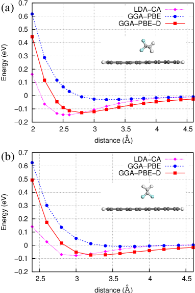
We performed LDA and GGA calculations when depositing one PVDF on 8-ZGNR as changing the distance between the two from 2.0 Å to 4.6 Å and the dipole direction of PVDF, parallel and perpendicular to 8-ZGNR. In order to reduce an intrinsic error due to the small number of basis sets, basis set superposition error (BSSE), we consider corrections for the error by introducing ghost orbital basis sets Stone (1996); Boys and Bernadi (1970). We compare binding energies at each distance with LDA and GGA, respectively. Binding energies are energy difference between total system (PVDF deposited on 8-ZGNR) and separated system (8-ZGNR, PVDF). They are calculated by following formula, 8-ZGNRPVDF8-ZGNR, ghost atoms of PVDFPVDF, ghost atoms of 8-ZGNR, CP means ‘counterpoise’ correction Stone (1996), and ghost atoms have only pseudo atomic orbitals without potential Boys and Bernadi (1970).
In Fig. 1(a), dotted (dashed) line represents binding energies calculated by LDA (GGA) with parallel dipole of PVDF to 8-ZGNR. The binding energy of PVDF on 8-ZGNR from LDA (GGA) is 145 meV (30 meV) and the distance between them is 2.5 Å (3.2 Å) (parallel dipole direction to the surface, see inset of Fig. 1(a)). These values agree well with tendency of LDA and GGA calculations, i.e., overbinding in LDA and underbinding in GGA. When dipole direction of PVDF is perpendicular to 8-ZGNR, binding energies are also plotted in Fig. 1(b) under LDA and GGA calculations. The binding energy is 77 meV and 8 meV, and the distance between PVDF and 8-ZGNR is 3.0 Å and 3.6 Å for LDA and GGA calculations, respectively. From those results, we confirm that parallel dipole of PVDF is more stable than perpendicular dipole of PVDF on 8-ZGNR irrespective of the approximations.
In order to consider the vdW interaction between PVDF and 8-ZGNR, we added vdW correction energy to the DFT total energy (),
| (1) |
where is the usual self-consistent Kohn-Sham energy. The vdW energy () is given by
| (2) |
Here, is the distance between atoms and . is the coefficient between atom and which can be written as where and are homonuclear coefficient and static polarizability of atom A(B). and are the vdW radii. The singularity at small distances is eliminated by the short-ranged damping function .
| (3) |
where . and are free parameters. To calculate , we use a method proposed by A. Tkatchenko and M. Scheffler Tkatchenko and Scheffler (2009). In the method, we can calculate the effective parameters, and corresponding to and respectively from the ground state electronic density. This improves the description of weakly bonded systems compared with empirical ones Tkatchenko and Scheffler (2009).
We added this vdW correction to GGA calculations with Perdew-Burke-Ernzerhof (PBE) Perdew et al. (1996) functionals using well-known free parameters, and Tkatchenko and Scheffler (2009), , , and , shown in Table I. The summation in Eq. (2) is done for atoms within 500 Å.
| Chu and Dalgarno (2004) | |||
|---|---|---|---|
| H | 6.5 | 1.2 | 4.5 |
| C | 46.6 | 1.70 | 12.0 |
| F | 9.5 | 1.47 | 3.8 |
The binding energy including the BSSE correction Boys and Bernadi (1970), 8-ZGNRPVDF8-ZGNRPVDF, is plotted as solid line in Fig. 1(a) and (b). It gives the binding energy of 129 meV and the distance of 2.8 Å in (a) and 73 meV 3.2 Å in (b). They are between LDA and GGA limits and quite close to the LDA results. From all results, nevertheless vdW correction changes binding energy and bond length between PVDF and 8-ZGNR, it is not a crucial part in determining the bonding nature and electronic structures.
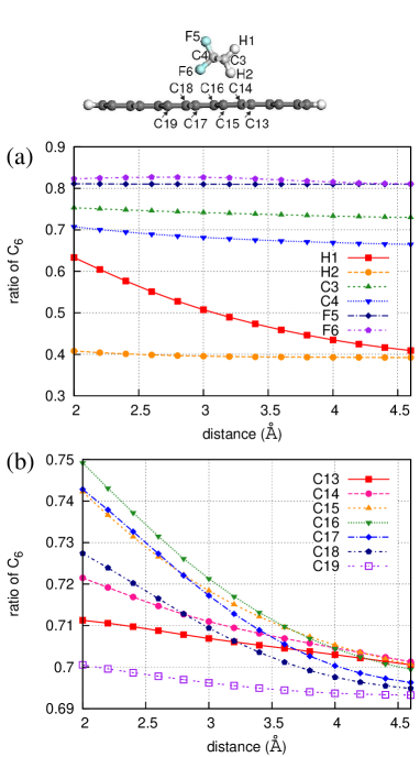
Additionally, the effective coefficients, in the system decrease from those of free atoms and changes when system configurations are altered. If we change the height between PVDF and ZGNR, the between the nearest pair atoms belong to each material decreases significantly while those for well separated pair atoms decreases slightly [Fig. 2]. Because different hybridizations states for atoms in each system give various coefficiensts, all values are changed, respectively. The ratio of to is plotted in the Fig. 2(a) and (b). The ratio for all PVDF atoms are shown in Fig. 2(a) and the ratio for some 8-ZGNR atoms which are close to PVDF are presented in Fig. 2(b). The ratios are in the range of 0.37 to 0.6 for Hydrogen atoms, 0.64 to 0.75 for Carbon atoms, and about 0.81 for Fluorine atoms. Especially, the closest atom between PVDF and 8-ZGNR, H1 (Fig. 2(a)), has large variation of the ratio, and carbon atoms at both edges of 8-ZGNR have constant ratio of 0.64.
Finally, the vdW correction is also performed under the external electric fields. We found that the LDA results are still trustful. Based on electrostatic forces, the dipole of PVDF tends to align with parallel direction to external electric fields. With the electric fields of 0.1 V/Å whose direction is perpendicular to ZGNR surface, the perpendicular PVDF to ZGNR surface is more stable than the parallel one. The energy differece between perpendicular and parrallel direction of PVDF is 14 meV and 8 meV in LDA and vdW corrected GGA, respectively.
In conclusion, we carried out LDA, GGA, and vdW corrected GGA calculations for a single PVDF on 8-ZGNR. Our vdW corrected GGA-PBE calculatons show that binding energies, distances between PVDF and ZGNR, and the response under the external electric fields lead to the same conclusion to ones from LDA calculations with very small quantitative differences.
References
- Novoselov et al. (2004) K. S. Novoselov, A. K. Geim, S. V. Morozov, D. Jiang, Y. Zhang, S. V. Dubonos, I. V. Grigorieva, and A. A. Firsov, Science 306, 666 (2004).
- Berger et al. (2006) C. Berger, Z. Song, X. Li, X. Wu, N. Brown, C. Naud, D. Mayou, T. Li, J. Hass, A. N. Marchenkov, et al., Science 312, 1191 (2006).
- Geim and Novoselov (2007) A. K. Geim and K. S. Novoselov, Nat. Mat. 6, 183 (2007).
- Fujita et al. (1996) M. Fujita, K. Wakabayashi, K. Nakada, and K. Kusakabe, J. Phys. Soc. Jpn. 65, 1920 (1996).
- Nakada et al. (1996) K. Nakada, M. Fujita, G. Dresselhaus, and M. S. Dresselhaus, Phys. Rev. B 54, 17954 (1996).
- Son et al. (2006a) Y.-W. Son, M. L. Cohen, and S. G. Louie, Phys. Rev. Lett. 97, 216803 (2006a).
- Han et al. (2007) M. Y. Han, B. Özyilmaz, Y. Zhang, and P. Kim, Phys. Rev. Lett. 98, 206805 (2007).
- Chen et al. (2007) Z. Chen, Y.-M. Lin, M. J. Rooks, and P. Avouris, Phys. E 40, 228 (2007).
- Li et al. (2008a) X. Li, X. Wang, L. Zhang, S. Lee, and H. Dai, Science 319, 1129 (2008a).
- Wang et al. (2008) X. Wang, Y. Ouyang, X. Li, H. Wang, J. Guo, and H. Dai, Phys. Rev. Lett. 100, 206803 (2008).
- Son et al. (2006b) Y.-W. Son, M. L. Cohen, and S. G. Louie, Nature 444, 347 (2006b).
- Lee et al. (2005) H. Lee, Y.-W. Son, N. Park, S. Han, and J. Yu, Phys. Rev. B 72, 174431 (2005).
- Jung et al. (2009) J. Jung, T. Pereg-Barnea, and A. H. MacDonald, Phys. Rev. Lett. 102, 227205 (2009).
- Tombros et al. (2007) N. Tombros, C. Jozsa, M. Popinciuc, H. T. Jonkman, and B. J. van Wees, Nature 448, 571 (2007).
- Wolf et al. (2001) S. A. Wolf, D. D. Awschalom, R. A. Buhrman, J. M. Daughton, S. von Molnar, M. L. Roukes, A. Y. Chtchelkanova, and D. M. Treger, Science 294, 1488 (2001).
- Hod et al. (2008) O. Hod, V. Barone, and G. E. Scuseria, Phys. Rev. B 77, 035411 (2008).
- Hod and Scuseria (2008) O. Hod and G. E. Scuseria, ACS Nano 2, 2243 (2008).
- Hod et al. (2007) O. Hod, V. Barone, J. E. Peralta, and G. E. Scuseria, Nano Lett. 7, 2295 (2007).
- Cervantes-Sodi et al. (2008) F. Cervantes-Sodi, G. Csanyi, S. Piscanec, and A. C. Ferrari, Phys. Rev. B 77, 165427 (2008).
- Li et al. (2008b) Z. Li, J. Yang, and J. G. Hou, J. Am. Chem. Soc. 130, 4224 (2008b).
- Kan et al. (2008) E. J. Kan, X. J. Wu, Z. Y. Li, X. C. Zeng, J. L. Yang, and J. G. Hou, J. Chem. Phys. 129, 084712 (2008).
- Zheng et al. (2008) F. Zheng, G. Zhou, Z. Liu, J. Wu, W. Duan, B.-L. Gu, and S. B. Zhang, Phys. Rev. B 78, 205415 (2008).
- Bune et al. (1998) A. V. Bune, V. M. Fridkin, S. Ducharme, L. M. Blinov, S. P. Palto, A. V. Sorokin, S. G. Yudin, and A. Zlatkin, Nature 391, 874 (1998).
- Malin et al. (2007) L. Malin, I. Stolichnov, and N. Setter, J. App. Phys. 102, 114101 (2007).
- Naber et al. (2005) R. C. G. Naber, C. Tanase, P. W. M. Blom, G. H. Gelinck, A. W. Marsman, F. J. Touwslager, S. Setayesh, and D. M. de Leeuw, Nat. Mat. 4, 243 (2005).
- Hu et al. (2009) Z. Hu, M. Tian, B. Nysten, and A. M. Jonas, Nat. Mat. 8, 62 (2009).
- Lovinger (1983) A. J. Lovinger, Science 220, 1115 (1983).
- Zheng et al. (2009) Y. Zheng, G.-X. Ni, C.-T. Toh, M.-G. Zeng, S.-T. Chen, K. Yao, and B. Özyilmaz, Appl. Phys. Lett. 94, 163505 (2009).
- Ansari and Giannelis (2009) S. Ansari and E. P. Giannelis, J. Polym. Sci., Part B 47, 888 (2009).
- Duan et al. (2004) C.-G. Duan, W. N. Mei, W.-G. Yin, J. Liu, J. R. Hardy, S. Ducharme, and P. A. Dowben, Phys. Rev. B 69, 235106 (2004).
- Choi et al. (2000) J. Choi, C. N. Borca, P. A. Dowben, A. Bune, M. Poulsen, S. Pebley, S. Adenwalla, S. Ducharme, L. Robertson, V. M. Fridkin, et al., Phys. Rev. B 61, 5760 (2000).
- Noda et al. (2000) K. Noda, K. Ishida, A. Kubono, T. Horiuchi, H. Yamada, and K. Matsushige, Jpn. J. Appl. Phys. 39, 6358 (2000).
- Noda et al. (1999) K. Noda, K. Ishida, T. Horiuchi, K. Matsushige, and A. Kubono, J. Appl. Phys. 86, 3688 (1999).
- Ducharme et al. (2005) S. Ducharme, T. Reece, C. Othon, and R. Rannow, Device and Materials Reliability, IEEE Transactions on 5, 720 (2005), ISSN 1530-4388.
- Soler et al. (2002) J. M. Soler, E. Artacho, J. D. Gale, A. García, J. Junquera, P. Ordejón, and D. Sánchez-Portal, J. Phys.: Condens. Matter 14, 2745 (2002).
- Perdew et al. (1996) J. P. Perdew, K. Burke, and M. Ernzerhof, Phys. Rev. Lett. 77, 3865 (1996).
- Troullier and Martins (1991) N. Troullier and J. L. Martins, Phys. Rev. B 43, 1993 (1991).
- Boys and Bernadi (1970) S. F. Boys and F. Bernadi, Mol. Phys. 19, 553 (1970).
- Stone (1996) A. J. Stone, The Theory of Intermolecular Forces (Oxford University Press: New York, 1996), ISBN 0-19-855884-8.
- Grimme (2006) S. Grimme, J. Comput. Chem. 27, 1787 (2006).
- Barone et al. (2008) V. Barone, M. Casarin, D. Forrer, M. Pavone, M. Sambi, and A. Vittadini, J. Comput. Chem. 30, 934 (2008).
- Tkatchenko and Scheffler (2009) A. Tkatchenko and M. Scheffler, Phys. Rev. Lett. 102, 073005 (2009).
- Perdew and Wang (1986) J. P. Perdew and Y. Wang, Phys. Rev. B 33, R8800 (1986).
- Ortmann et al. (2006) F. Ortmann, F. Bechstedt, and W. G. Schmidt, Phys. Rev. B 73, 205101 (2006).
- Wu and Yang (2002) Q. Wu and W. Yang, J. Chem. Phys. 116, 515 (2002).
- Zimmerli et al. (2004) U. Zimmerli, M. Parrinello, and P. Koumoutsakos, J. Chem. Phys. 120, 555 (2004).
- Thonhauser et al. (2004) T. Thonhauser, V. R. Cooper, S. Li, A. Puzder, P. Hyldgaard, and D. C. Langreth, Phys. Rev. B 76, 125112 (2004).
- Chu and Dalgarno (2004) X. Chu and A. Dalgarno, J. Chem. Phys. 121, 4083 (2004).
- Bondi (1964) A. Bondi, J. Phys. Chem 68, 441 (1964).
- Yan et al. (1996) Z. Yan, J. F. Babb, A. Dalgarno, and G. W. F. Drake, Phys. Rev. A 54, 2824 (1996).