Status of the Cylindical-GEM project for the KLOE-2 Inner Tracker
Abstract
The status of the R&D on the Cylindrical-GEM (CGEM) detector foreseen as Inner Tracker for KLOE-2, the upgrade of the KLOE experiment at the DAΦNE –factory , will be presented. The R&D includes several activities: i) the construction and complete characterization of the full-size CGEM prototype, equipped with 650 m pitch 1-D longitudinal strips; ii) the study of the 2-D readout with XV patterned strips and operation in magnetic field (up to 1.5T), performed with small planar prototypes in a dedicated test at the H4-SPS beam facility; iii) the characterization of the single-mask GEM technology for the realization of large-area GEM foils.
keywords:
GEM , tracking , KLOE-21 Introduction
After the completion of the KLOE data taking [1], the proposal of a new run with an upgraded KLOE detector, KLOE-2 [2], at an upgraded DAΦNE machine has been accepted and will start in spring 2010 [3]. The KLOE-2 physics program will be focused on physics coming from the interaction point (IP), where the -meson is produced: , , and decays as well as interference and search for physics beyond the Standard Model. The improvement in the reconstruction performance for tracks near the interaction region is then of fundamental importance for the accomplishment of this physics program.
After a first phase with the installation of the low-energy (LET) [4] and high-energy (HET) [5] tagging systems for the identification and study of events, the detector will be upgraded with the insertion of an Inner Tracker (IT) between the beam pipe and the Drift Chamber (DC) inner wall. A crucial design parameter is the resolution on the decay point, occurring within few cm from the IP. An accurate study on quantum interferometry measurement showed that an improvement on this resolution of about a factor of 3 with respect to the present value ( 6 mm) is required [6]. The IT contribution to the overall material budget has to be carefully taken into account in order to minimize multiple scattering contribution to the track momentum resolution and photon conversions before the DC volume. The main requirements for the IT can be summarized as:
-
1.
m and m spatial resolutions;
-
2.
total material budget below 2 of the radiation length X0;
-
3.
5 kHz/cm2 rate capability.
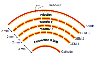
The adopted solution is the Cylindrical-GEM (CGEM) [6], a triple-GEM detector composed by concentric cylindrical electrodes (fig. 1): Cathode, 3 GEM foils for the multiplication stage (gain 104) and Anode, acting also as the readout circuit. The high rate capability of the GEM (up to 1 MHz/mm2 [7]) makes this detectors suitable to be placed near the interaction point of a high-luminosity collider machine.
The IT will be then composed by 5 concentric CGEM detection layers at radii from 13 cm, to preserve the - quantum interference region, to 23 cm due to the constrained from DC inner wall at 25 cm. The total active length for all layers will be 70 cm. The anode readout of each CGEM will be segmented with 650 m pitch XV patterned strips with a stereo angle of , for a total of about 30,000 FEE channels. The Front-End Electronics for the IT is based on the new GASTONE ASIC [8], a 64 channels chip composed by four different stages: a charge preamplifier with 20mV/fC sensitivity, a shaper, a leading-edge discriminator with a programmable threshold and a monostable stretcher of the digital signal, to synchronize with the KLOE Level1 trigger.
In the following the main stages of the R&D project [6] will be discussed: i) the construction and complete characterization of a full-scale CGEM prototype, ii) the study of the XV strip readout configuration and its operation in magnetic field and iii) the construction and characterization of a large area GEM realized with the new single-mask photolitografic technique.
2 Cylindrical-GEM prototype
A full-scale CGEM prototype has been built with 15 cm radius and 35 cm active length [9]. The cylindrical electrodes have been obtained from very light polyimide foils (50 m thick for GEMs, 100 m for Cathode, 100 m for Anode) rolled onto machined PTFE cylinders, acting as molds, and then glued exploiting the vacuum bag technique. The cylinders are then inserted one into the other and fiberglass annular flanges are glued at the ends, acting as spacers for the gaps and as supporting mechanics [10]. The CGEM is therefore a low-mass, fully cylindrical and dead-zone free GEM based detector with no support frames required inside its active area. The anode was patterned with 650 m pitch longitudinal strips, reconstructing the r- coordinate, for a total of 1538 axial strips. The chamber, tested with X-rays to check the uniformity over the large surface, has been then equipped with the 16-channels prototype of GASTONE [8] and tested at the CERN PS with a 10 GeV pion beam. The results show the expected spatial resolution from a digital readout of 650 m pitch strips [11] and a 99.6 efficiency.
3 XV readout and operation in magnetic field
A typical orthogonal XY readout can not be used for the inner tracker, due to its cylindrical geometry. The final IT readout will be then performed with an XV pattern of strips and pads engraved on a polyimide foil substrate, 100 m thick (fig. 2).
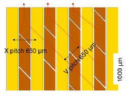
The X strips with 650 m pitch will provide the r- coordinate while the pads, connected through internal vias to form V strips with 650m pitch, will provide the z coordinate. This quite innovative readout solution was not implemented on the CGEM prototype, therefore its characteristics have been extensively studied with dedicated planar chambers. In addition, since the IT will operate inside KLOE’s magnetic field, the effects on the cluster formation and electronics readout had to be studied.
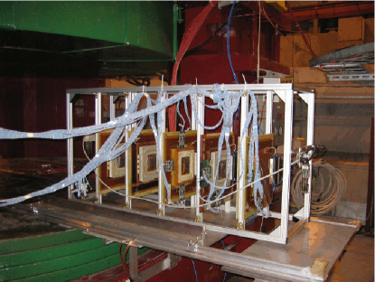
To address these issues a dedicated test has been done at the H4 permanent facility, setup at the CERN-SPS 150GeV pion beam line within the RD51 Collaboration [12]. Five 10x10 cm2 planar triple-GEM (PGEM) detectors with 650 m pitch readout have been assembled and succesfully tested: four chambers with standard XY readout and the fifth with the XV readout under investigation. The setup was 1 meter long with detectors placed equidistantly with the XV chamber placed in the center (fig. 3). For the operation in magnetic field, the GOLIATH magnet was used, providing a field adjustable up to 1.5 T perpendicular to the horizontal beam-plane.
KLOE-2 inner tracker technical design report
To fully cover the area illuminated by the SPS beam, the planar chambers were partially equipped with 22 digital readout GASTONE boards, 32 channels each, four on each XY chamber and six on the XV chamber. The coincidence of 6 scintillators (3x3 cm2) readout by silicon photomultipliers, three upstream and three downstream, provided the trigger signal for the acquisition. The same working point of the CGEM prototype has been used: Ar/CO2 (70/30) gas mixture and operating voltages Vfields = 1.5/3/3/5 kV/cm and VGEM = 390/380/370 V (VG = 1140V, Gain=2104). The GASTONE threshold was set at 3.5 fC.
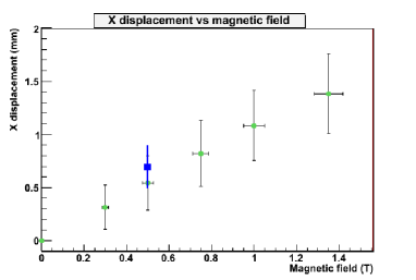
The effect of the magnetic field (B) is twofold: a displacement dx and a spread of the charge over the readout plane. The expected values obtained from simulation studies of our chambers done with GARFIELD are dx=600 m and =200 m at B=0.5 T [6]. In the test beam configuration the magnetic field effect was mainly present on the X-view. The setup used to measure the displacement on the XV chamber due to the magnetic field is shown in fig. 4.
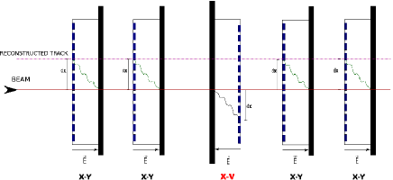
All four XY chambers are likewise oriented, with the same anode-cathode configuration, and provide the external tracking system for the XV chamber which is instead in a cathode-anode arrangement, reversed with respect to the other chambers. Since the XY chambers are subject to the same Lorentz force, the reconstructed track will be shifted by the same offset dx with respect to the true track trajectory. The displacement in the XV chamber instead will be of the same magnitude dx but with opposite direction, due to the reversed cathode-anode arrangement. First, with zero magnetic field (B=0 T), the setup was aligned to a few micrometer precision and then, with the magnetic field turned on, the total displacement (D) between the track reconstructed by the XY telescope and the point in the XV chamber was measured: D = 2dx (fig. 4). The displacement dx was measured for 5 values of the magnetic field and found in good agreement with the value obtained from the GARFIELD simulation at B=0.5 T (fig. 5).
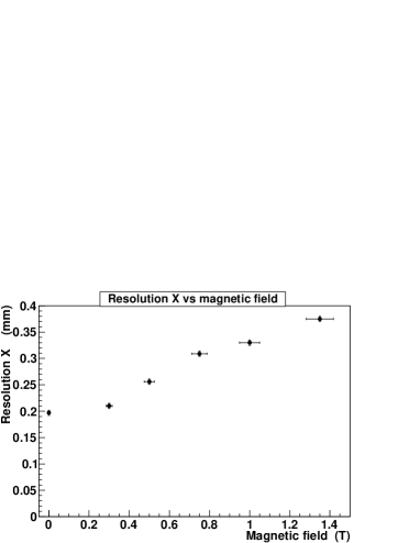
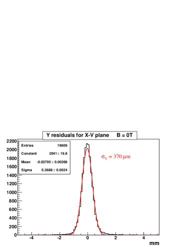
To study the XV chamber performance, we measured the resolution in both X and Y coordinates: the X coordinate is measured directly from the X strips while the Y coordinate is obtained from the crossing of both X and V strip readout. Fig. 6 shows the resolution on the X coordinate as a function of the magnetic field, the values ranging from 200 m at B=0 T up to 380 m at B=1.35 T. The resolution on the Y coordinate measurement is 370 m at B=0 T, in agreement with what expected from the digital readout of the two X and V views (fig. 7).
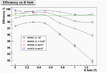
The performance of the front-end chip GASTONE have been studied measuring the cluster size and reconstruction efficiency, defined as the presence of a cluster in the XV chamber when a candidate track was reconstructed using four XY chambers. Fig. 8 shows the reconstruction efficiency measured as a function of the magnetic field and operating the XV chamber with four different gain values. The efficiency for the nominal KLOE magnetic field B=0.52 T and voltage settings was measured to exceed 99, slightly decreasing at higher B fields. In fact the increase of the magnetic field leads to a larger spread of the charge over the readout strips and causes a reduction of the charge seen by each single pre-amplifier channel, with a consequent efficiency drop. Thus the increase of the magnetic field requires for higher gains to efficiently operate the chamber. The variation of the magnetic fields within the KLOE-2 planned values (0.3-0.5 T), to improve the acceptance for low momentum tracks, has a negligible effect on the reconstruction efficiency in the voltage range around our working point.
The charge sharing, grounding and cross-talk between strips could have been in principle different for X and V views, due to the different readout geometry. Our measurements demonstrated good behavior of both X and V readout views, which appear to have equalized response.
4 Large Area GEM
To build the IT outermost layer, a GEM foil as large as 1440x700 mm2 is needed. This foil can be obtained splicing 3 separate 480x700 mm2 foils with a technique that we have developed, using an epoxy adhesive and a vacuum bag. The urge for larger GEM foils has driven a change of the production procedure by CERN TS-DEM-PMT laboratory, switching to a single-mask etching, more suitable for a large surface [13]. The new GEMs have quasi-cylindrical holes and a new characterization is necessary. In order to check the uniformity of the new single-mask GEMs over a large area, we will build a 700x300 mm2 planar triple-GEM. Dedicated tools for the stretching, handling and assembling of such large foils have been designed and realized. The chamber, that will be the largest GEM detector ever operated, will be equipped with the GASTONE 64-channels final release and readout with the Off Gastone Electronic (OGE) Board [6]. A dedicated test beam of the Large Area GEM is foreseen this year at the CERN. The external tracking system will be provided by the four XY chambers used for the XV readout studies, replacing the XV chamber with the Large Area GEM.
5 Finalizing the project: 3-D Finite Element simulation
ANSYS [14] finite element 3-D simulation of the CGEM has been developed to estimate the structural response under tensile loads: induced strain, stress and displacements [15]. A detailed characterization of the materials has been done to implement an accurate description of the mechanical behavior. The model has been then validated by comparison with measurements done with CGEM and PGEM prototypes.
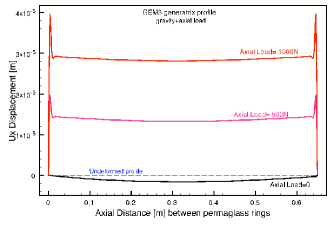
Fig. 9 shows the results obtained with the simulation of the 700 mm length CGEM for the generatrix profile of a GEM foil, with gravitational effect only and once an axial load is applied to improve the stability of the foils. The gravitational sag is therefore negligible and the maximum value of the expected radial displacement is 20 m for 500 N axial load and becomes 40 m with 1000 N. The peculiar effect observed on the edges of the distributions is due to the presence on the GEM foil edges of 5 mm of kapton connecting two more rigid structures radially displaced: the GEM active zone (two-side copper-clad kapton foil) and the Permaglass ring. This originates an S-shaped deformation which translates into the observed egde effect. Besides this, the radial displacement is constant in the GEM active zone and similar distributions have been obtained for Cathode and Anode showing that the structure of the CGEM gaps is preserved.
6 Conclusions
The construction, safe operation and extensive test of an almost full-size Cylindrical-GEM prototype has demonstrated the feasibility of such a novel low-mass and dead-zone-free vertex detector. The final readout configuration has been validated with the successful test of the small planar prototypes operated in magnetic field: very good results in terms of spatial resolution, efficiency and cluster size have been obtained. A large planar GEM prototype will be built using foils realized with the new single-mask technique to test their quality and homogeneity together with the GASTONE 64-channels readout final release. The R&D phase on Cylindrical-GEM is practically concluded. The project of the KLOE-2 Inner Tracker has been recently approved and its construction will start this year in order to be ready for insertion in the KLOE detector by summer 2011.
References
- [1] F. Bossi,E. De Lucia,J. Lee-Franzini, S. Miscetti, M. Palutan and KLOE Collaboration, Rivista del Nuovo Cimento Vol.31, N.10 (2008).
- [2] R. Beck et al, KLOE-2 collaboration, Expression of interest for the continuation of the KLOE physics program at DAΦNE upgraded in luminosity and in energy, http://www.lnf.infn.it/lnfadmin/direzione/roadmap/LoIKLOE.pdf
- [3] R. Beck et al, KLOE-2 collaboration, A proposal for the roll-in of the KLOE-2 detector, LNF-07/19(IR),INFN-LNF, Frascati, 2007.
- [4] D. Babusci et al., doi:10.1016/j.nima.2009.09.110
- [5] F. Archilli et al., doi:10.1016/j.nima.2009.06.082
- [6] F. Archilli et al., KLOE-2 Collaboration, Technical Design Report of the Inner Tracker for the KLOE-2 experiment , arXiv:1002.2572v1 and LNF-10/3(P) INFN-LNF, Frascati,2010.
- [7] PhD thesis of Marco Poli Lener: Triple-GEM detectors for the innermost region of the muon apparatus at the LHCb experiment, http://doc.cern.ch/archive/electronic/cern/preprints/thesis/thesis-2006-013.pdf.
- [8] A. Balla et al., Nucl. Inst. & Meth. A 604 (2009) 23.
- [9] G. Bencivenni et al., Nucl. Inst. & Meth. A 572 (2007) 168 and Nucl. Inst. & Meth. A 581 (2007) 221.
- [10] G. Bencivenni et al., NSS Conference Record, 2007 IEEE, Volume 6 pp. 4666-4670.
- [11] G. Bencivenni et al., NSS Conference Record, 2008 IEEE, 19-25 Oct. 2008 pp. 1345-1346 .
- [12] RD51 Proposal, CERN-LHCC-2008-011 (2008)
- [13] M. Villa et al., paper presented at this Conference.
- [14] www.ANSYS.com
- [15] L. Quintieri et al., Finite Element Model of the Cylindrical GEM Detector as New Inner Tracker of Kloe2 and Mechanical Characterization of the Employed Materials, LNF-09/12(IR), INFN-LNF, Frascati, 2009.