Non-dispersive optics using storage of light
Abstract
We demonstrate the non-dispersive deflection of an optical beam in a Stern-Gerlach magnetic field. An optical pulse is initially stored as a spin-wave coherence in thermal rubidium vapour. An inhomogeneous magnetic field imprints a phase gradient onto the spin wave, which upon reacceleration of the optical pulse leads to an angular deflection of the retrieved beam. We show that the obtained beam deflection is non-dispersive, i.e. its magnitude is independent of the incident optical frequency. Compared to a Stern-Gerlach experiment carried out with propagating light under the conditions of electromagnetically induced transparency, the estimated suppression of the chromatic aberration reaches 10 orders of magnitude.
pacs:
42.50.Gy, 42.50.Nn, 42.15.Fr, 07.55.GeElectromagnetically induced transparency (EIT) is a quantum interference effect that allows to render otherwise opaque atomic media transparent 10. (2005). Destructive interference of absorption amplitudes here allows for a suppression of optical absorption. Media prepared under the conditions of electromagnetically induced transparency have interesting properties, as an extreme reduction of the optical group velocity Hau et al. (1999); Kash et al. (1999); Budker et al. (1999) and allow for applications e.g. in the fields of metrology Scully and Fleischhauer (1992); Katsoprinakis et al. (2006); Kominis et al. (2003), non-linear optics Kash et al. (1999); Harris and Hau (1999) and quantum information science Duan et al. (2001a); Chaneliere et al. (2005); Eisaman et al. (2005); Duan et al. (2001b). More recently, spatially resolved EIT has been demonstrated, and in two experiments the storage of images has been reported Shuker et al. (2008); Vudyasetu et al. (2008). This has prospects in the context of all-optical transmission and processing of arbitrary images. We have recently shown that slow light can be spatially deflected by a Stern-Gerlach magnetic field, yielding evidence for a non-zero effective magnetic moment of the dark polariton, the quasiparticle physically associated with slow-light propagation Karpa and Weitz (2006). Due to the extremely spectrally sharp variation of the group velocity, the beam deflection is highly dispersive Sautenkov et al. (2007), i.e. when the light is slowed down by say a factor two, as is possible by variation of the signal beam frequency by a few kHz in the spectrally sharp EIT transparency window, the deflection doubles. In another experiment, the deflection of an optical beam has been achieved by means of phase imprinting from a spatially inhomogeneous off-resonant optical field during light storage Schnorrberger et al. (2009).
Here we demonstrate the non-dispersive deflection of an optical beam traversing a medium under the conditions of electromagnetically induced transparency. Our experiment is based on a light pulse stored as a spin wave in thermal rubidium vapour, onto which a phase gradient is imprinted by a spatially inhomogeneous Stern-Gerlach magnetic field. The observed beam deflection upon reacceleration of the optical pulse is found to be independent of the signal beam frequency, thus suppressing chromatic aberrations. More generally, we provide a proof of principle experiment demonstrating that the dynamic deceleration and acceleration of light possible under the conditions of electromagnetically induced transparency allows to surpass limitations of conventional optics. We also wish to point out that the obtained beam deflection cannot be understood in terms of Fermat’s principle of the shortest optical path.
Before proceeding we note that the reduction of chromatic and spherical aberrations has a long history in the field of both light and matter wave optics. For example, state of the art optical objectives employ high order corrections to reduce chromatic aberrations over the entire visible spectrum Bas (McGraw Hill, New York, 1995). While those optical elements rely on light traversing a spatial sequence of optical elements with different dispersional properties (different glass materials), our approach uses temporal variations of the optical group velocity in an atomic gas and phase imprinting.
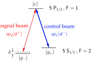
Our experiment can be understood qualitatively by considering an ensemble of atoms with a -type coupling scheme, where and denote two stable ground states with Zeeman quantum numbers differing by two and a spontaneously decaying state, see Fig. 1. A schematic of our experiment is shown in Fig. 2. The atoms are irradiated by two copropagating optical fields, a weak ”signal” field with frequency and a stronger ”control” field with frequency coupling the levels , and , respectively. The magnetic bias field is oriented along the beam axis. Storage of light is performed in a standard way Phillips et al. (2001); Liu et al. (2001) by adiabatically reducing the intensity of the control beam to zero, so that a signal beam pulse is first slowed and then coherently stored as a spin-wave coherence in the atomic medium. During the light storage, the phase of the spin wave coherence oscillates with the corresponding atomic eigenfrequency. The atoms are subject to a transverse magnetic field gradient, so that the eigenfrequency is not spatially homogeneous over the signal beam profile. Within a storage time , the imprinted accumulated phase shift in the Zeeman ground state coherence is
| (1) |
where denotes the position along the magnetic field gradient. In our experiment both the magnetic bias field and the incident beams are collinear (along the z-axis), so that the differential Zeeman splitting between the ground states and is , with as the hyperfine g-Factor and the Bohr magneton . In the presence of the field gradient, the accumulated phase shift is spatially inhomogeneous, which will lead to an optical path length variation upon reacceleration of the signal pulse that is dependent on the transverse position . This is similar as in the directed emission of phased-array antennas in the microwave regime Art (Artech house, Boston, 1994). For a constant magnetic field gradient , the associated angle beam deflection is easily determined by setting for small deflection angles. For a magnetic gradient constant in time over a storage period , we arrive at
| (2) |
In our experiment, the magnetic field gradient is active both during the propagation time of the optical signal beam pulse through the dark state medium and the stored light phase. In first order (we continue to assume small deflection angles), the total deflection is expected to be the sum of the two contributions , where is the Stern-Gerlach angle deflection of a propagating slow light pulse acquired during the phases before and after the storage period of the pulse. In a mechanical model, this contribution to the total deflection can be determined by , where with the Stern-Gerlach force on an atom-light polariton with effective magnetic moment , and L denotes the cell length Karpa and Weitz (2006). For a group velocity we have , and arrive at
| (3) |
where for the sake of simplicity we have set the group velocity to be constant during the course of the deceleration and retrieval procedure. Note that formally also Eq. 2 can be obtained in this “mechanical” model, if we assume that the stored light polaritons cannot be moved in the presence of the Stern-Gerlach field, but rather accumulate a change in wavevector during the stored light phase that changes the propagation direction of the regenerated beam after retrieval.
It is instructive to compare the variations of the deflection angle in the incident optical frequency. Whereas the variation of the deflection angle acquired during the stored light phase resembles that of an optical grating and is as low as in the spectrally narrow transmission width of an EIT resonance, e.g. kHz in our experiment. In contrast, the optical group velocity varies by a factor of order unity over the spectral width of the dark resonance, so that the chromatic aberration of the Stern-Gerlach deflection of stored light is suppressed with respect to that acquired in the propagating light phase by an expected factor , i.e. ten orders of magnitude!
In our proof of principle experiment, we do not pulse the magnetic field gradient so that both contributions to beam deflection can be studied, and experimentally compared. Our setup is a modified version of an earlier described apparatus Karpa and Weitz (2006); Karpa et al. (2009). A 50 mm long cell containing thermal 87Rb-vapor and 10 torr of neon buffer gas is placed inside a magnetically shielded region, in which a field coil generates the (longitudinal) magnetic bias field.
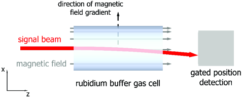
To produce the desired transverse magnetic field gradient, a -metal strip oriented parallel to the propagation axis of the optical fields is mounted near the cell, resulting in a lowering of the magnetic field at the cell side near the strip. The buffer gas cell apparatus is heated to temperatures about 85∘C. Both signal and control optical fields are derived from the same grating stabilized laser diode source locked to the hyperfine component of the rubidium D1-line near 795 nm. The emitted beam is split into two paths and guided through separate acousto-optical modulators (AOMs) to enable controlled variations of the two-photon detuning and of the individual intensities of the control and signal fields respectively. The beams are spatially overlapped and, after being fed through a polarization maintaining optical fibre, expanded to a 2 mm beam diameter and with opposite circular polarizations sent to the rubidium cell. The used beam powers upon entry in the cell were typically 60 and 330 for the signal and control beams respectively. In the limit that the signal beam intensity being always much less than the intensity of the control beam, most of the relevant population is in the sub-level of the 5 S1/2 ground state. In this case the levels and of the simplified level scheme of Fig. 1 correspond to the and Zeeman sub-levels of the 5 S hyperfine ground state component respectively.
After traversing the rubidium cell, the position of the deflected signal beam is monitored. As the CCD-camera used for position monitoring does not have sufficient temporal resolution to allow for a selective detection of the signal beam during readout time of the storage of light sequence, an acousto-optical modulator is placed before the camera. The modulator is driven with a radiofrequency gating pulse of typically length during retrieval of the signal beam, so that position detection is active only in this temporal window. The position of the retrieved signal beam pulse is determined by mapping the intensity distribution onto a CCD camera and calculating the center of intensity position of the digitized image.
In initial experiments, we have mapped out the magnetic field gradient by recording dark resonance spectra with the driving optical beams passing the experiment cell at different transverse positions. In these preparatory measurements the signal beam intensity was monitored by a photodiode. From a series of recorded spectra, the field gradient was determined to be (1.21 0.07) G/mm for a magnetic bias field of 240 mG.
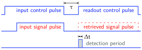
Subsequently, we moved to a storage of light sequence, and monitored the deflection of the reaccelerated beam. A schematic of the used experimental pulse sequence is shown in Fig. 2. Storage of light is achieved by irradiating the cell with rectangularly shaped signal and control beam pulses of 130 and 150 duration respectively, which were switched off adiabatically such that the falling edge of the signal pulse temporally coincided with the falling edge of the control pulse. This leaves the signal pulse stored as a spin-wave in the atomic medium, with the magnetic field gradient imprinting an accumulated, spatially inhomogeneous phase shift onto the atomic spin coherence. After a storage period of variable duration, the coupling laser is turned back on and the stored coherence is reaccelerated into a propagating optical field. The regenerated atomic dipoles have acquired a transversal phase gradient , and we expect an angle deflection of the regained optical beam.
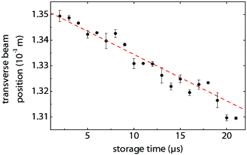
Fig. 3 shows the result of a position measurement of the retrieved signal beam recorded for different storage period durations. The measurement gives the signal beam position on our CCD camera placed at a distance of 1.7 m behind the rubidium cell. In between the cell and the camera a 1:1 optical telescope was located consisting of two 200 mm focal length lenses used for focusing of the signal beam into the acoustooptic modulator required for temporal gating of the retrieved signal beam pulse, with the first lens 0.6 m apart from the cell. The experimental data can be well fitted assuming the expected linear dependence of the deflection induced by phase imprinting on the storage time (see Eq. 2). To verify that the phase imprinting indeed causes an angular deflection of the reaccelerated beam, after the telescope an additional lens (f=300 mm focal length) was inserted at the end of the signal beam path, with its focal plane being congruent with the detection plane of the CCD camera. In this configuration, only angle changes cause a change of the camera position signal. An angle deflection by the cell at given storage time leads to a variation of the beam position on the camera for small angles.
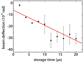
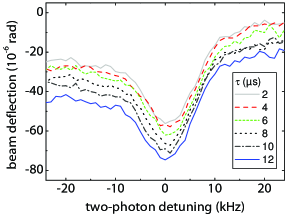
Fig. 4 shows the obtained relative angle deflection as a function of the storage time recorded with this configuration. At our maximum available storage time of 20 , the obtained beam deflection reaches rad. We attribute an observed increase in uncertainty of the data for long storage times to the here relatively small power of the retrieved signal light, which increases the uncertainty in determining the relatively small position variations after the short focal length lens used in this experimental configuration. The data points have been fitted with a linear function, yielding a slope of the deflection angle versus the storage time of (1.30 0.09) rad/s. Within the quoted experimental accuracy, this value is in good agreement with the result calculated from Eq. 2, which predicts a value (1.35 0.08) rad/s. The error bar of the expected value is dominated by the experimental uncertainty in the determination of the magnetic field gradient (described above). It is noteworthy that in case that the polaritons would behave as massive particles that could be moved during light storage by the applied field gradient, a transverse beam displacement increasing quadratically with time would be expected. Both a transverse displacement and a quadratic dependence are inconsistent with the experimental data, which shows an angular deflection that increases linearly with storage time, in agreement with our theoretical model.
From our model, we also expect the beam deflection accumulated in the stored light phase to be independent of the optical group velocity. As the principal experimental result of this Letter, Fig. 4 shows the observed Stern-Gerlach deflection for different storage times as the function of the two-photon detuning . For a given storage time , one observes a clear variation of the deflection on the two-photon detuning. We attribute this dependence to deflection contributions acquired during the propagating light phases of the storage procedure, i.e. at times when the optical control field intensity is different from zero during beginning and readout of the storage sequence (see Fig. 2). The Stern-Gerlach deflection acquired for a propagating polariton is clearly dispersive and depends on the optical group velocity (see Eq. 3), so that the observed change in deflection is well understood as due to the variation in optical group velocity when sweeping over the two-photon resonance. When the storage time is varied - the figure shows data recorded in incremental temporal steps of 2 - the experimental spectra exhibit a basically equidistant displacement towards larger deflections. Noticeably, the increase for larger storage times appears to be equidistant for all shown values of the two-photon detuning, yielding evidence for a non-dispersive deflection contribution acquired during the storage phase. A cross section at corresponds to the situation shown in Fig. 4. The observed angle deflection can be well described as the sum of two contributions: (i) a dispersive Stern-Gerlach deflection originating from the interaction of moving quasiparticles of non-zero effective magnetic moment with the magnetic field gradient and (ii) a non-dispersive contribution arising from the phase gradient imprinted during light storage. We point out that the observed non-dispersive deflection effect also allows for the sensitive detection of magnetic field gradients by evaluating the beam position of the retrieved signal pulse. The obtained sensitivity increases linearly with the storage time, and the non-dispersiveness of the deflection represents a clear advantage over techniques based on propagating optical fields Karpa and Weitz (2006).
To conclude, we have investigated the deflection of an optical beam by phase-imprinting by a Stern-Gerlach magnetic field during the storage of light. We find that the dispersion is efficiently suppressed with respect to that obtained in a Stern-Gerlach deflection experiment of propagating atom-light polaritons, realizing a proof-of-principle demonstration of non-dispersive optics enabled by the dynamic variation of the optical group velocity in electromagnetically induced transparency.
We expect that the observed effects allow for applications in the field of coherent image storage and processing with electromagnetically induced transparency. Related examples include the development of all-optical deflectors or adaptive optics components. It is an intriguing question, whether with advances in the field of solid-state electromagnetically induced transparency Longdell et al. (2005), optical elements as e.g. lenses can be developed with the dynamical variation of group velocity allowing for chromatic aberration-free imaging. We also anticipate applications in quantum memories, where the obtained deflection may allow for the addressing of parallel channels Chaneliere et al. (2005); Eisaman et al. (2005). A different perspective includes applications in the field of magnetic field metrology. The described techniques may be used to characterize inhomogeneous magnetic field distributions from the far-field deflection pattern of the retrieved signal field after light storage.
We thank W. Ketterle and F. Vewinger for helpful discussions. Financial support from the Deutsche Forschungsgemeinschaft is acknowledged.
References
- 10. (2005) see e.g.: M. Fleischhauer, A. Imamoglu, and J. P. Marangos, Rev. Mod. Phys. 77, 633 (2005).
- Hau et al. (1999) L. V. Hau, S. E. Harris, Z. Dutton, and C. H. Behroozi, Nature 397, 594 (1999).
- Kash et al. (1999) M. M. Kash, V. A. Sautenkov, A. S. Zibrov, L. Hollberg, G. R. Welch, M. D. Lukin, Y. Rostovtsev, E. S. Fry, and M. O. Scully, Phys. Rev. Lett. 82, 5229 (1999).
- Budker et al. (1999) D. Budker, D. F. Kimball, S. M. Rochester, and V. V. Yashchuk, Phys. Rev. Lett. 83, 1767 (1999).
- Scully and Fleischhauer (1992) M. O. Scully and M. Fleischhauer, Phys. Rev. Lett. 69, 1360 (1992).
- Katsoprinakis et al. (2006) G. Katsoprinakis, D. Petrosyan, and I. K. Kominis, Phys. Rev. Lett. 97, 230801 (2006).
- Kominis et al. (2003) I. K. Kominis, T. W. Kornack, J. C. Allred, and M. V. Romalis, Nature 422, 596 (2003).
- Harris and Hau (1999) S. E. Harris and L. V. Hau, Phys. Rev. Lett. 82, 4611 (1999).
- Duan et al. (2001a) L.-M. Duan, J. I. Cirac, and P. Zoller, Science 292, 1695 (2001a).
- Chaneliere et al. (2005) T. Chaneliere, D. N. Matsukevich, S. D. Jenkins, S.-Y. Lan, T. A. B. Kennedy, and A. Kuzmich, Nature 438, 833 (2005).
- Eisaman et al. (2005) M. D. Eisaman, A. André, F. Massou, M. Fleischhauer, A. S. Zibrov, and M. D. Lukin, Nature 438, 837 (2005).
- Duan et al. (2001b) L. Duan, M. D. Lukin, J. I. Cirac, and P. Zoller, Nature 414, 419 (2001b).
- Shuker et al. (2008) M. Shuker, O. Firstenberg, R. Pugatch, A. Ron, and N. Davidson, Phys. Rev. Lett. 100, 223601 (2008).
- Vudyasetu et al. (2008) P. K. Vudyasetu, R. M. Camacho, and J. C. Howell, Phy. Rev. Lett. 100, 123903 (2008).
- Karpa and Weitz (2006) L. Karpa and M. Weitz, Nature Physics 2, 332 (2006).
- Sautenkov et al. (2007) V. A. Sautenkov, H. Li, Y. V. Rostovtsev, and M. O. Scully, arXiv:quant-ph/0701229v1 (2007).
- Schnorrberger et al. (2009) U. Schnorrberger, J. D. Thompson, S. Trotzky, R. Pugatch, N. Davidson, S. Kuhr, and I. Bloch, Phys. Rev. Lett. 103, 033003 (2009).
- Bas (McGraw Hill, New York, 1995) see e.g.: S. Inoue and R. Oldenberg in ”Handbook of Optics”, Vol II, M. Bass (ed.) (McGraw Hill, New York, 1995).
- Phillips et al. (2001) D. F. Phillips, A. Fleischhauer, A. Mair, R. L. Walsworth, and M. D. Lukin, Phys. Rev. Lett. 86, 783 (2001).
- Liu et al. (2001) C. Liu, Z. Dutton, C. H. Behroozi, and L. V. Hau, Nature 409, 490 (2001).
- Art (Artech house, Boston, 1994) see, e.g.: R. J. Mailloux, ”Phased array antenna handbook” (Artech house, Boston, 1994).
- Karpa et al. (2009) L. Karpa, G. Nikoghosyan, F. Vewinger, M. Fleischhauer, and M. Weitz, Phys. Rev. Lett. 103, 093601 (2009).
- Longdell et al. (2005) J. J. Longdell, E. Fraval, M. J. Sellars, and N. B. Manson, Phys. Rev. Lett. 95, 063601 (2005).