Polarized Raman spectroscopy of nearly-tetragonal BiFeO3 thin films
Abstract
BiFeO3 thin films can be epitaxially stabilized in a nearly-tetragonal phase under a high biaxial compressive strain. Here we investigate the polarized Raman spectra of constrained BiFeO3 films with tetragonal-like (BFO-T) , rhombohedral-like (BFO-R) and multiphase (BFO-T+R) structure. Based on analysis of the number and symmetry of the Raman lines, we provide strong experimental evidence that the nearly-tetragonal films are monoclinic ( symmetry) and not tetragonal . Through the Raman mapping technique we show localized coexistence of BFO-T and BFO-R phases with the relative fraction dependent on the film thickness.
pacs:
78.30.-j, 63.20.Dj, 75.85.+tConstant demand for miniaturization in modern devices have provided a big stimulus for research into multi-functional materials. BiFeO3, or simply BFO, is a prototypical multiferroic material due to the simultaneous co-existence of ferroelectric, ferroelastic and anti-ferromagnetic order. It is also currently widely investigated as it offers room-temperature multi-functionality after very high polarization values were reported in 2003 for films grown on SrTiO3 (STO) substrates.wang2003 However, it can be argued that the rhombohedral structure of BFO-R possess significant difficulties and challenges. For example, the ferroelectric polarization of BFO-R is directed along the (111) direction giving rise to eight possible polarization orientations. As a result, ferroelectric switching is complicated and very hard to control for any meaningful multi-functionality. Therefore, BFO phase of different symmetry, which in principle could address these issues, is desired .
This interest increased after recently it was predicted theoretically and confirmed experimentally that the structure and properties of BiFeO3 films under a large, biaxial compressive strain could deviate significantly from the bulk material into a ”super-tetragonal” structure with an extremely high ratio.ederer2005 ; yun2006 ; bea2009 ; lisenkov2009 ; zeches2009 ; hatt2010 This phase, in some sense, appears incommensurable to its rhombohedral counterpart and requires a thorough investigation much along the lines that bulk BFO has received. Apart from possibly higher ferroelectric polarization values and significantly simpler switching properties, this phase is especially suitable for ultra-thin film applications where the strain effect is maximum.
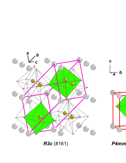
Based on earlier theoretical predictions, it was anticipated that tetragonal BFO could belong to the (#99) space group ederer2005 . But careful X-ray diffraction analysis of BFO films deposited on LaAlO3(LAO) and YAlO3(YAO) substrates show evidence of monoclinic distortionsbea2009 ; zeches2009 , and very recently ab-initio calculations have also indicatedhatt2010 that the monoclinic (#9) structure is indeed energetically more favorable than the tetragonal structure, when the compressive strain is greater than 4%. The three structures that could be used to describe strained BFO thin films grown on LAO substrates are shown in Fig.1. Following the theoretical study of Hatt et al.,hatt2010 at low strains only small differences from the structure of the bulk material are predicted and observed and although the strained film is of lower monoclinic symmetry (), its structure remains rhombohedral-like and to a good approximation can be described by the space group. For compressive strains greater than 4% the structure changes dramatically and becomes tetragonal-like with . This structure can be approximated by the symmetry, but further refinement, supported by first principles calculations, leads again to symmetry. As pointed out in Refs.zeches2009 ; hatt2010 , the strain induced R-T transition of BiFeO3 is in fact isosymmetric. Although theoretically well grounded, there is to our knowledge no reports of direct experimental confirmation that at a local level the structure of BTO-T films is monoclinic. Strong experimental evidence for structure of BFO-T films has readily been found in the polarized Raman spectra presented and discussed below.
There are several reports on the Raman spectra of BiFeO3 obtained from single crystal,fukumura2007 ; cazayous2007 polycrystalline samplesrout2008 ; yuan2007 and thin films on SrTiO3 substrates.singh2005 ; yang2008 . These spectra are similar with respect to the frequencies of the observed Raman lines and their assignment is based on the rhombohedral structure. As an exception, Singh et al.singh2005 have assumed that the BFO/STO thin film they studied has tetragonal structure, which seems not to be correct. Indeed, the spectra of Singh et al.singh2005 are practically identical to those from strain-free rhombohedral BiFeO3fukumura2007 ; cazayous2007 ; rout2008 ; yuan2007 and, in addition, the type of substrate (SrTiO3) and the film thickness (600 nm) presuppose rhombohedral-like structure.hatt2010
In this letter we report the polarized Raman spectra of true tetragonal-like BiFeO3 (BFO-T) obtained in strained 70 nm and 100 nm epitaxial BiFeO3 films on (001)-LaAlO3 substrates. The spectra are compared to those of relaxed rhombohedral-like BiFeO3 (BFO-R) obtained from 200 nm BiFO3/LaAlO3 and 80 nm BiFO3/40 nm SrRuO3/LaAlO3 films. Based on analysis of the number and symmetry of the Raman lines expected for the tetragonal and monoclinic BFO structures, the experimental spectra provide strong evidence that the real structure is of symmetry. We also show by Raman mapping of selected areas on the 100 nm BFO/LAO and 200 nm BFO/LAO films that BFT-T and BFO-R phases can coexist in partly relaxed BFO/LAO films.
BiFeO3 thin films were deposited on single crystal LaAlO3 substrates by pulsed laser deposition technique using 248 nm, KrF excimer laser with 1.5 J/cm2 fluence and 10 Hz pulse repetition rate. A ceramic target with 20% Bi-excess was used to compensate the Bi loss during deposition. The substrate temperature of 700∘C, oxygen pressure 100 mTorr and cool down at 5∘C/min with 600 Torr oxygen pressure were used for all the depositions. Additionally, BFO films were deposited on 40 nm SrRuO3(SRO) buffered LAO substrates. X-ray diffraction measurements show BFO films (70-200 nm) deposited directly on LAO substrates to have an out-of-plane lattice constant value of approximately 4.66 Å, whereas SRO-buffered films exhibit a diffraction peak near the bulk rhombohedral BFO position (pseudocubic Å). In-plane lattice parameter measurements through reciprocal space maps show BFO/LAO films to be highly strained to the substrate ( Å).
The primitive cell contains two formula units. The total number of -point phonon modes is 20 (). Of these, 13 are both Raman and IR active, five ( are silent, and two () are acoustical modes. The primitive cell of the structure (Fig.1) contains one formula unit. The total number of -point phonon modes is 10 (. Of these, seven are both Raman and IR active, one is only Raman active and two are acoustic modes. The elementary cell of structure (Fig.1) is base-centered and contains four formula units. All atoms are non-centrosymmetrical positions. The number of -point phonon modes is 30 . Three of them are acoustic modes. modes are both Raman and infrared active. As the experimentally obtained out-of-plane lattice parameter of the BFO-T films is larger than the in-plane parameters, it is plausible to accept that the surface of the film is parallel to the corresponding (001) planes. We note here that the [100]t and [010]t directions of structure, which are parallel to [100]c and [010]c quasicubic directions of the LAO substrate, become [110]m and [-110]m directions for the structure. Therefore, the coordinate systems of the Raman tensors for the and differ by 45 degree rotation around the -axis.
The scattering intensity of a phonon mode of given symmetry is proportional to , where and are unit vectors parallel, respectively, to the polarization of the incident and scattered radiation. The Raman tensors for modes of different symmetry of the , and structures have the form:
and
For backward scattering from the (001) surface and have no -component and the intensity of the modes (for ) will a priori be zero. One therefore expects observation in the experimental Raman spectra of BFO-T of only four Raman lines in the case of and much higher number of lines for the structure. The polarization selection rules for these Raman mode symmetries in all available exact scattering configurations from the tetragonal or monoclinic surfaces are given in Table I. For the structure the intensities are averaged over the expected two twin variants with interchangeable and parameters (four twin variants if accounting for the polarization direction). Similarly, for the BFO-R films four twin variants (eight if accounting for the polarization direction) with orientation of the rhombohedral [111]r direction along any of the four quasicubic directions of the LAO substrate may coexist. The polarization selection rules for the and structures, given in Table I, are the expected averaged Raman intensities with and along the cubic , , , and directions, under the assumption that the twin variants occupy equal parts of the scattering volume.
| Mode | ||||||
|---|---|---|---|---|---|---|
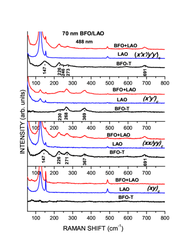
Figure 2 illustrates on the example of 70 nm BFO/LAO film how the spectra of BFO-T were obtained. Due to the small film thickness, the original spectra are a superposition (BFO+LAO) of Raman signals from the film (BFO) and the substrate (LAO). The LAO spectra were measured separately with the same scattering configuration from film-free substrate surface and then subtracted from the original spectra using GRAMS AI software.
In Figure 3 are compared the spectra of BFO-T, obtained with 515 nm and 488 nm excitation from two strained BFO-T films, with the corresponding spectra of relaxed BFO-R, obtained with 488 nm excitation. As it follows from Table I, the modes of BRO-R structures are much stronger with parallel and than with crossed and scattering configurations. This allows to identify unambiguously the peaks at 77, 142, 176, and 221 cm-1 in the BFO-R spectra as corresponding to the modes. The assignment of the 77 cm-1 line to an mode differs from that proposed by Cazayous et al.,cazayous2007 but as a whole the BFO-R spectra are similar to those reported for single crystal and bulk BFO.fukumura2007 ; cazayous2007 ; rout2008 ; yuan2007 . The weaker peaks at 279, 359, 369, 473, 530, and 615 cm-1 can be assigned to modes.
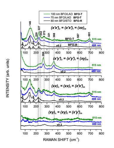
The Raman spectra of BFO-T are well reproduced in all scattering configurations. The large number of Raman lines is consistent with monoclinically distorted tetragonal-like structure, thus ruling out the simple structure. Indeed, for the structure one expects only three lines in the and one line in the spectra, whereas the number of experimentally observed lines is much higher. For the same scattering configurations 14 and 13 modes are allowed, respectively, for the structure. We can therefore assign the Raman lines at 146, 227, 273, 587, and 691 cm-1, pronounced in the () and ( spectra, to modes of symmetry and the lines at 220, 242, 266, and 368 cm-1, seen in the () and ( spectra, to modes of symmetry
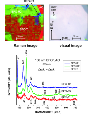
With increasing BFO/LAO film thickness the rhombohedral BFO-R phase appears as secondary phase in the 100 nm BFO/LAO film and dominant phase in the 200 nm BFO/LAO film. This is illustrated for area on the surface of 100 nm BFO/LAO thin film, which has been Raman mapped with 1.5 m step comparing the Raman spectra. As it follows from Fig.4, the studied area is characterized by three types of spectra: BFO-R1, BFO-R2, and BFO-T. The Raman line frequencies of BFO-R1 and BFO-R2 correspond to the rhombohedral phase and the spectra differ by only relative line intensities. This can be explained by assuming that the BFO-R1 and BFO-R2 spectra are obtained from twin variants of BFO-R with different orientation with respect to and . One can therefore conclude, that the twin variants of the BFO-R phase are of micrometer size. As to the twin variants of the BFO-T phase, their Raman spectra should be practically undistinguishable, as from structural considerations one expects the relation for the components of the Raman tensor. The observation of the R-phase is probably due to the release of the substrate strain effect with increasing thickness.zeches2009
In conclusion, polarized Raman spectroscopy was used to study tetragonally strained BFO-T films on LAO substrates and relaxed rhombohedral BFO-R films on LAO substrates with SRO buffer layers. We provide strong experimental evidence that the tetragonal-like structure is of monoclinic symmetry and the simple tetragonal structure has to be ruled out. Five of the fourteen modes and four of the thirteen modes expected for the structure have been identified This is consistent with the results of recent first principles calculationshatt2010 . It is also demonstrated very clearly that BFO-R and BFO-T coexist at the micrometer scale with the R-phase gradually becoming the dominant phase with increasing thickness.
Acknowledgements.
This work was support in part by the State of Texas through the Texas Center for Superconductivity at the University of Houston and by NSF MRSEC (Grant No.DMR-0213985).References
- (1) J.Wang, J.B. Neaton, H.Zheng, V.Nagarajan, S.B.Ogale, B.Liu, D.Viehland, V.Vaithyanathan, D.G.Schlom, U.V.Waghmare, N.A. Spaldin,K.M. Rabe and M.Wuttig and R.Ramesh, Science 299, 1719 (2003).
- (2) C. Ederer and N. A. Spaldin, Phys. Rev. Lett. 95, 257601 (2005).
- (3) K. Y. Yun, D. Ricinschi, T. Kanashima, and M. Okuyama, Appl. Phys. Lett. 89, 192902 (2006).
- (4) S. Lisenkov, D. Rahmedov, and L. Bellaiche, Phys. Rev. Lett. 103, 047204 (2009).
- (5) H. Béa, B. Dupé, S. Fusil, R. Mattana, E. Jacquet, B. Warot-Fonrose, F. Wilhelm, A. Rogalev, S. Petit, V. Cros, A. Anane, F. Petroff, K. Bouzehouane, G. Geneste, B. Dkhil, S. Lisenkov, I. Ponomareva, L. Bellaiche, M. Bibes, and A. Barthélémy, Phys. Rev. Lett. 102, 217603 (2009).
- (6) R. J. Zeches, M. D. Rossell, J. X. Zhang, A. J. Hatt, Q. He, C.-H. Yang, A. Kumar, C. H. Wang, A. Melville, C. Adamo, G. Sheng, Y.-H. Chu, J. F. Ihlefeld, R. Erni, C. Ederer, V. Gopalan, L. Q. Chen, D. G. Schlom, N. A. Spaldin, L. W. Martin, and R. Ramesh, Science 326, 977 (2009).
- (7) A. J. Hatt, N. A. Spaldin, and C. Ederer, Phys. Rev. B 81, 054109 (2010).
- (8) H. Fukumura, S. Matsui, H. Harima, T. Takahashi, T. Itoh, K. Kisoda, M. Tamada, Y. Noguchi, and M. Miyavama, J. Phys.: Condens. Matter 19, 365224 (2007).
- (9) M. Cazayous, D. Malka, D. Lebeugle, and D. Colson, J. Appl. Phys. 91, 071910 (2007).
- (10) D. Rout,. K.-S. Moon, and S.-J. L. Kang, J. Raman Spectrosc. 40, 618 (2009).
- (11) G. L. Yuan, S. W. Or, and H. L. W. Chan, J. Phys. D: Appl. Phys. 40, 1196 (2007).
- (12) M. K. Singh, S. Ryu, and H. M. Jang, Phys. Rev. B 72, 132101 (2005).
- (13) Y. Yang, J. Y. Sun, K. Zhu, Y. L. Liu, and L. Wan, J. Appl. Phys. 103, 093532 (2008).