Modelling Heat Transfer of Carbon Nanotubes
Abstract
Modelling heat transfer of carbon nanotubes is important for the
thermal management of nanotube-based composites and nanoelectronic
device. By using a finite element method for three-dimensional
anisotropic heat transfer, we have simulated the heat conduction and
temperature variations of a single nanotube, a nanotube array and a
part of nanotube-based composite surface with heat generation. The
thermal conductivity used is obtained from the upscaled value from
the molecular simulations or experiments. Simulations show that
nanotube arrays have unique cooling characteristics due to its
anisotropic thermal conductivity.
Key words: Carbon nanotube, finite element
analysis, nanoscale heat transfer, nanotechnology, thermal conductivity.
Citation detail: Yang, X.-S., “Modelling Heat Transfer of Carbon Nanotubes”, Modelling and Simulation in Materials Science and Engineering, Vol. 13, 893-902 (2005).
1 Introduction
Carbon nanotubes (CNT) have attracted worldwide attention in both research and industry since the discovery by Iijima in 1991 [17]. Extensive studies of this novel nanocomposite material suggests that it has many potential applications such as nanomachines, nanoelectronic and nanomedicine due to its super-high stiffness, strength and resilience, and its exceptional electrical and thermal properties ([18, 6, 11, 12, 13]). It bas become one of the hottest research topics in the important nanotechnology. There have been extensive studies about the properties of carbon nanotubes ([1, 2, 15, 34, 38, 40]). In addition, there have important development concerning the multi-scale computer simulation techniques to imbue the continuum-based models with more realistic details at quantum and atomistic scales [7]. There are many technical challenges such as the experimental studies of the mechanical, thermal and electronic properties of CNTs(e.g.,[9, 32, 34]). Even though there have been extensive theoretical modelling studies in term of atomistic, molecular dynamics (MD), quantum mechanic and continuum approach, many computational issues remain unsolved or unsatisfied. Among these important issues are the modelling of the nano-rheological behaviour and heat transfer of carbon nanotubes, the fluid flow inside a nanotube or interconnected nanotube networks.
The modelling of nanothermal process such as heat transfer and thermal stress of carbon nanotubes has interesting challenges. The complexity of the nanotubes makes the analytical approach intractable, while the experimental measurement is very expensive and time-consuming. This makes the computational modelling a better quick and yet efficient alternative for studies and analysis of the structure of carbon nanotubes and nanocomposites ([8, 22, 23, 26, 30, 36, 28]). Finite element analysis has been quite successful in the modelling of macroscale phenomena such as heat transfer, engineering mechanics and fluid flow. However, special care should be taken before it can apply to model the nanoscale structure. In recent years, there have been several interesting studies using the continuum mechanical method to study the microscale structure and mechanical properties (e.g.,[1, 8, 22, 23, 26, 31]). However, there has been little progress in the modelling of heat transfer and thermal management of carbon nanotubes or nanotube-based composites.
This paper aims at the development of the finite element analysis of the nanoscale heat transfer of carbon nanotubes. We first formulate the finite element method for 3-D heat transfer analayis of nanotubes. Then, we study the heat conduction and temperature variations of single-walled nanotubes, nanotube array and nanotube-based composites to simulate the thermal behavoir such as nano-electronic devices and nanoswitch, followed by the discussion and implication of the simulation results.
2 Finite Element Formulation
In the modelling of carbon nanotubes, molecular modelling is a discrete approach and the conventional finite element method is a continuum-based approach. Finite element analysis (FEA) on nanoscales is different from both of these approaches. In fact, it shall be the combination of these two approaches and bridging their gaps. Finite element method uses the most elaborate finite element method while its input materials properties are estimated from the molecular-based modelling.
2.1 Scaling Gaps
Carbon nanotubes and nanocomposites have a length scale range from the molecular scale to macroscopic scales. There are two conventional computational methods working on different scales. Molecular-based computational modelling tries to predict the mechanical and thermal properties using quantum mechanics and discrete ab initio calculations ([2, 33, 4, 24, 28]), while macroscopic solid mechanics treats the media as a continuum using homogenized bulk material properties ([1, 12, 41]). However, the intermediate nanoscale is just between these two extreme scales. A proper methodology is needed to bridge these two scales in the hierarchy.
Such important intermediate scaling of material properties only start to emerge recently. Odegard et al [26] proposed an instructive and interesting approach. Another promising method is molecular mechanical modelling approach ([37], [22]). These methods often use the molecular level phonon theories, and the thermal conductivity can be derived [4].
2.2 Thermal Conductivity
The thermal conductivity (K) for carbon nanotubes varies greatly and it is highly anisotropic as the conductivity is much higher along the axis of the nanotube than in other directions. Although it is extremely difficult in obtaining the experimental measurements, there have some important progress in the experimental studies of the thermal properties of carbon nanotubes ([16, 35, 32]). Small et al [35] discussed in detail the mesoscopic experimental measurements of phonon thermal transport and thermoelectronic phenomena in individual carbon nanotubes. They measured the temperature distributions in electrically heated individual multiwalled carbon nanotubes with a scanning thermal microscope and a microfabricated suspended device to obtain the thermal conductivity.
The bulk thermal conductivity is estimated to be in the range of W/mK , and it varies with temperature and size of the nanotubes ([35],[4],[24]). However, there is a significant gap between experiment-derived values and theoretical predictions. Choi et al used 2000 W/mK for thermal conductivity [5], and Kim et al obtained a value of 3000 W/mK for the room temperature thermal conductivity of individual multiwalled nanotubes [21]. Biencuk et al demonstrated that samples loaded with 1 wt unpurified single-walled carbon nanotubes showed a 70 increase in thermal conductivity at 40 K and 125 at room temperature [3]. Small et al obtained that the ’bulk’ thermal conductivity at room temperature is over 3000 W/mK , while the earlier results suggested a lower value of 36 W/mK for the densely-packed single-walled carbon nanotube mat, and with the estimated bulk longitude thermal conductivity of a nanorope in the range of 1600-6000 W/mK ([35, 16]). In addition, there is also a large difference between single tube and bulk measurements and there is more strong temperature dependence in individual nanotubes than in the bulk measurements as clearly pointed by Small et al [35]. Che et al theoretically predicted the thermal conductivity along the tube axis approaches 2980 W/mK for (10,10) single-walled nanotubes for tube length up to 40nm with a thickness of 1 . They also predicted that a value of 950 W/mK for nanotube bundles along the tube axis and the much lower thermal conductivity of 5.6 W/mK in the direction perpendicular to the tube, and this value is comparable to the graphite out-of-plane thermal conductivity 5.5 W/mK [4]. Similarly, the mechanical properties are also the unusually unique with very high Young’s modulus 1000-3700 GPa and Poisson’s ratio 0.18-0.3 ([20, 38, 9, 34, 15, 36]). In fact, the thermal conductivity of nanotubes is highly anisotropic with the value along the tube axis usually two orders higher than the perpendicular to the tube. Thus, the aligned nanotubes, nanoropes and bundles are also highly anisotropic.
The highly anisotropic properties in thermal conductivity and large difference between single-tube and bulk measurements suggest that more extensive studies are needed. From the point of view of finite element analysis, the formulation shall be specially taken care of so that the method shall be able to analyze the anisotropic characteristics in heat transfer of nanotubes. For the continuum-based finite element method, there have been many ways to ensure this capability. However, for the finite element analysis on the nanoscale, some modifications and special choice of element types should be investigated. In the rest of the section, we will formulate the essential implementation of the finite element analysis for the modelling heat transfer of carbon nanotubes.
2.3 Continuum-Based Finite Element Formulation
Once the parameters of thermal properties are estimated or upscaled from the molecular simulations or ab initio simulations, an equivalent continuum-based finite element formulation can be used. The main procedure is the same as the conventional finite element procedure, and many finite element algorithms and element types can be similarly constructed. However, the continuum-based finite element method only works from the scale of micron to very large scales [41]. For smaller scales, the continuum-based representative volume does not work on the atomistic scale. There are two ways to overcome this difficulty. One way is to use the discrete molecular-mechanical simulations based on the quantum mechanics, and this may leads to very large numbers of computations ([8, 22, 29]). The other is to use the discrete-based modelling to upscale the continuum-equivalent material properties such as thermal conductivity. Then, the normal procedure of finite element analysis can be used.
For finite element analysis of nanoscale heat transfer of carbon nanotubes, two natural models for element types are: truss model and hexagon model. The truss model is very popular in solid mechanics for the analysis of engineering structures. Odegard et al uses a truss model to simulate the mechanical behavior of the nano-structured systems in terms of the displacement of the atoms and the total molecular potential energy [26]. The hexagon model will be studied in more detail in this paper. The beam and truss models are based on 1-D line model, and thus it is unlikely to give accurate results for 3-D structures, especially the geometry is more complex. The anisotropic feature of the heat conduction of carbon nanotubes requires the full 3-D formulation of heat transfer equation, and proper initial and boundary conditions shall be implemented.
In the rest of the paper, we will formulate a full 3-D finite element method and use the hexagon element with six nodes being the atoms of the basic carbon structure. We will then simulate the heat transfer of carbon nanotubes and compare different method for the same configuration so as to find a better and suitable method for the finite element method.
The governing equation of 3-D heat conduction can be written as
| (1) |
where are the principal thermal conductivities. and are density and specific heat capacity, respectively. is the rate of heat generation, and is the source term which is a known function of time and temperature .
For an ambient temperature and the typical temperature of the system, any temperature can be written as . The temperature variation is very small , and typically is the order of 1 K. Equivalently, we can define a dimensionless temperature
| (2) |
For the ambient room temperature and the typical temperature of interest, we have when , and when . In fact, we can choose any temperature of our interest so that the dimensionless temperature difference is .
By choosing the typical length , thermal conductivity W/mK , and time scale , the governing equation in the dimensionless form becomes
| (3) |
where and is a matrix depending on the anisotropic thermal conductivity. If there is no heat generation, then or . For a uniform time-independent heat source, .
Substituting into the above equation and after some elaborate calculations, the finite element formulation usually leads to a generic form
| (4) |
and
| (5) |
where are the coefficient matrix and the stiffness matrix, respectively. is the contribution of the heat source and boundary conditions.
3 Simulations and Results
Using the finite element method formulated in the above section, we can simulate some typical characteristics concerning the heat transfer of carbon nanotubes. We first study the heat conduction of a single nanotube, and then we investigate the heat conduction of an array of parallel nanotubes and the temperature variations of a nanodevice with heat generation.
Carbon nanotubes have three major types: armchair tubes [e.g., (n,n)], chiral tubes [e.g., (8,2)], and zigzag tubes such as (n,0) ([11],[36]). We shall focus on one type of the nanotube such as zigzag. For other types such as chiral or armchair, the methodology used is the same. Once the detail configuration of the nanotubes is known, the finite element nodes and elements are essentially the same. In all the following simulations, we assume all the carbon bond are in equal length with equal angles . The bulk thermal conductivity W/mK and the ratio of transverse to longitude thermal conductivity . Thus, the thermal conductivity matrix . The radius of the carbon nanotube is 1-1.5nm (normalized in the dimensional form as 1), while the length is 20nm (normalized as 1), and the thickness of the single-walled carbon nanotube is taken to 0.34nm ([30], [36]).
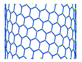
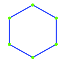
In the finite element simulations, we use two major element types: hexagonal element and beam element. The 6-noded hexagon element is the same structure as the basic carbon structure (see Figure 1). We shall present the results using these two element types and comparison will be made whenever relevant.
3.1 Heat Conduction of a Nanotube
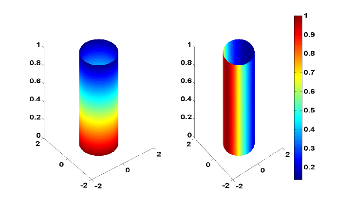
Nanoelectromechnical device such as nanoswitches may have many potential application in nanomedicine and nanoelectronics ([10],[35]). The thermal behavior of nanodevice and its heat management is of great interest and practical applications. For a single nanotube with a radius of 1nm and a length of 20 nm, by fixing the temperature or at one end and a radiation boundary at the other end with the ambient temperature , then heat conduction of the nanotube is computed. The left figure in Figure 2 shows the dimensionless temperature distribution at time . For the same carbon nanotube, if we fix the temperature at one contact line as , then transverse heat conduction leads to the temperature distribution shown on the right in the Figure 2. We can see that temperature decrease more quickly along the tube axis than that in the transverse direction, and this is because the anisotropic thermal conductivity of the nanotube.
For the practical purpose of modelling carbon nanotubes, the hexagonal elements and truss element essentially give essentially the same results. Thus, the choice of element types is for the convenience of computation and programming. However, when the structure is not thin, the full 3-D finite element method shall be used, and the hexagonal element generally works better.
3.2 Nanotube Array
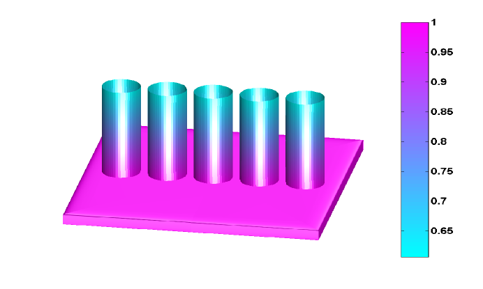
The simulation of an array of parallel carbon nanotubes is of more practical interest due to the experimental development of carbon nanotube frabrication and the amorphous carbon deposition [14]. This makes it more relevant to the nanoscale device. The heat transfer process on this scale is also important. For an array of parallelled nanotubes with a radius of 1nm and a spacing of 2.6nm, the base stays at a fixed temperature. The heat conduction of nanotube array is shown Figure 3 where the fixed base temperature or , and the ambient room temperature are used. The normalized temperature distribution is shown in color calculated using the hexagon elements. Temperature decrease more quickly along the direction of the axis of the nanotubes while the transverse temperature variation along the amorphous base is relatively small. This suggests that an array of carbon nanotubes can serve as a good cooling device or the nanotube array-based nanodevice may have very good heat dissipation properties.
3.3 Nanotube-Based Composite Surface With Heat Generation
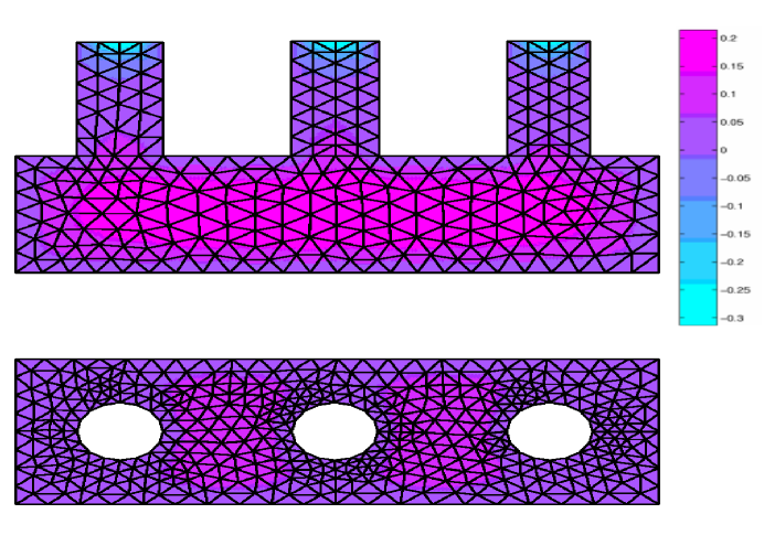
Nanotube-based composites are very promising due to its very unique mechanical, thermal and nanoelectronic properties. In practice, most nanoelectronic device will meet the problem of heat management due to the energy dissipation, heat generation and thermal transport. For a representative volume of such composite, the continuum-based simulation can focus on a regular array of nanotubes in parallel to each other. For the carbon nanotube array discussed earlier, we embedded them onto a composite surface and add the heat generation in the system. Figure 4 shows the two cross sections of three dimensional finite element results for a representative volume with three carbon nanotubes embedded onto a composite surface. The composite matrix is assumed to be isotropic and its thermal conductivity is taken as W/mK . The initial temperature is with a uniform heat generation rate . The ambient temperature is .
The simulation of this configuration is different from that in Figure 3 in that the present simulation uses the continuum-based tetrahedrons and thus the temperature distribution of the nanotubes is smoothly averaged, while the distribution in Figure 3 is based on hexagonal elements with the nodes being the same as the atoms. Due to the large number of atoms involved in the composites, the hexagonal elements are no longer practical and very time-consuming. The best choice for composites is the tetrahedron elements. We can see from Figure 4 that the temperature variations are much bigger along the nanotubes than in the transverse direction. This is because the thermal conductivity is much higher along the tube axis than in the other directions. This interesting characteristic of heat transfer may imply that the proper aligned nanotubes can have better cooling mechanism and thus better heat management properties. This may also imply that these composites can be better choice for nanoelectronic circuits and other nanomechanical device. From the above simulations, we see that carbon nanotubes have anisotropic heat conduction properties. The thermal conductivity is quite high compared with the usual materials.
4 Conclusions
We have formulated a finite element method to simulate the nanoscale heat transfer of a carbon nanotube and nanotube array. This method is based on the 3-D continuum-mechanical approach by using material parameters upscaled from the molecular simulations. The conventional finite element method usually works from the micron-scale up to a very large scale. As it reduces to atomistic scales, continuum approach needs special modifications. These include the upscaling and continuum-equivalent homogenization of material properties such as thermal conductivity. For a carbon nanotube with a radius of 1-1.5nm and a thermal conductivity of 2500 W/mK and ratio of 0.01 (perpendicular thermal conductivity to axial conductivity), the heat conduction and temperature variations with heat generation have been investigated under the possible conditions such as nanomechanical device. From the natural structure of the carbon nanotubes, we have used two major element types: the hexagonal elements and beam elements in the simulations. The comparison of the hexagonal elements and beam elements shows that for thin structures they give essentially the same results.
In our simulations, we assume the nanotubes are regular cylindrical shapes with a uniform thickness. In real nanotubes, caps are an important part of a carbon nanotube, thus the effect of the cap may not be negligible. In principle, we can use the the present method to simulate its effect. In addition, the multi-walled nanotubes and nanotube-based composites need more extensive studies concerning its thermal behavior and how their nanothermal behaviours differ from the single-walled nanotubes. These will become the computational modelling issues for further research.
Acknowledgement: The author thanks the two anonymous referees for their helpful comments that have improved the manuscript greatly.
References
- [1] Arroyo M. and Belytschko T., An atomistic-based finite deformation for single layer crystalline films. J. Mech. Phys. Solids, 50, 1941-77(2002).
- [2] Belytschko T., Xiao S. P., Schatz G. C., Ruoff R. S., Atomistic simulations of nanotube fracture, Phys. Rev. B, 65, 235430 (2002).
- [3] Biercuk M. J., Llaguno M. C., Radosavljevic M., Hyun J. K., Johnson A. T., Fisher J. E., Carbon nanotube composites for thermal management, Applied Phys. Lett., 80, 2767-2769 (2002).
- [4] Che J. W., Cagin T., Goddard III W., Thermal conductivity of carbon nanotubes, Nanotechnology, 11, 65-69 (2000).
- [5] Choi S. U. S., Zhang Z. G., Yu W., Lockwood F. E., Grulke E. A., Anomalous thermal conductivity enhancement in nanotube suspensions, Applied Phys. Lett., 79, 2252-2254 (2001).
- [6] Cornwell C. F. and L. T. Wille, Elastic properties of single-walled carbon nanotubes in compression, Solid State Comm., 101, 555-558 (1997).
- [7] Curtin W. A. and R. E. Miller, Atomistic/continuum coupling in computational materials science, Modelling Simul. Mater. Sci. Eng., 11, R33-R68 (2003).
- [8] Das P. S., Willie L. T., Atomistic and continuum studies of carbon nanotubes under pressure, Comput. Mat. Sci., 24, 159–162 (2002).
- [9] Demczyk B G, Wang Y. M., Cumings J., Hetman M., Han W., Zettl A., Ritchie, R. O., Direct mechanical measurement of the tensile strenth and elasic modulus of multiwalled carbon nanotubes, Materials Sci. Eng., A334, 173-178 (2002).
- [10] Dequesnes M., Rotkin S. V., Aluru N. R., Calculation of pull-in voltages for carbon nanotube based nanoelectromechanical switches, Nanotechnology, 13, 120-131 (2002).
- [11] Dresselhaus M. S., Dresselhaus G., Eklund P. C., Science of Fullerenes and Carbon Nanotubes, Academic Press, San Diego, CA, (1995).
- [12] Govindjee S., Sackman J. L., On the use of continuum mechanics to estimate the properties of nanotubes, Solid State Comm., 110, 227-230 (1999).
- [13] Goze C., Vaccarini L., Henrard L., Bernier P., Hernadez E., and Rubio A., Elastic and mechanical properties of carbon nanotubes, Synthetic metals, 103, 2500-2501 (1999).
- [14] Grujicic M., G. Cao, Gersten B., Optimization of the chemical vapour deposition process for carbon nanotubes fabrication, Appl. Surf. Sci., 191, 223-239 (2002).
- [15] Halicioglu T., Stress calculations for carbon nanotubes, Thin Solid Films, 312, 11-14 (1998).
- [16] Hone J., Whitney M., and Zettl A., Thermal conductivity of single-walled carbon nanotubes, Synthetic Metals, 103, 2498-2499 (1999).
- [17] Iijima, S., Helical microtubules of graphitic carbon, Nature, 354, 56-58 (1991).
- [18] Iijima, S., Single-shell carbon nanotubes of 1-nm diameter, Nature, 363, 603-605 (1993).
- [19] Ishii S., Miyamoto K., Oguri N., Horiuchi K., Sasaki T., Aoki N., Ochiai Y., Conduction carriers in multi-walled carbon nanotubes, Physica E, 19, 149-152 (2003).
- [20] Kelly B T, Physics of graphite, Applied Science, London (1981).
- [21] Kim P., Shi L., Majumdar A., McEuen P. L., Thermal transport measurement of individual multiwalled nanotubes, Phys. Rev. Lett., 87, 215502-1-4 (2001).
- [22] Li C. and Chou T. W., A structural mechanics approach for the analysis of carbon nanotubes, Int. J. Solid Struct., 40, 2487-2499 (2003).
- [23] Liu Y. J., Chen X. L., Evaluations of the effective material properties of carbon nanotube-based composites using a nanoscale representative volume element, Mech. Materials, 35, 69-81 (2003).
- [24] Maruyama S., A molecular dynamics simulation of heat conduction in finite length SWNTs, Physica B, 323, 193-195 (2002).
- [25] Nan C., Shi Z., Lin Y., A simple model for thermal conductivity of carbon nanotube-based composites, Chem. Phys. Lett., 375, 666-669 (2003).
- [26] Odegard G. M., Gates T. S., Nicholson L. M., and Wise K. E., Equivalent-continuum modelling of nano-structured materials, Composite Sci. Tech., 62, 1869-1880 (2002).
- [27] Pötschke P, Fornes T. D., Paul D. R., Rheological behavior of multiwalled carbon nanotube/polycarbonate composites, Polymer, 43, 3247-3255 (2002).
- [28] Pipes R. B., Hubert P., Helical carbon nanotube arrays: mechanical properties, Composite Sci. Tech., 62, 419-428 (2002).
- [29] Pipes R. B., Hubert P., Helical carbon nanotube arrays: thermal expansion, Composite Sci. Tech., 63, 1571-79 (2003).
- [30] Popov V. N., Van Doren V. E., Balkanski M., Elastic propertis of crystals of single-walled carbon nanotubes, Solid State Comm., 114, 395-399 (2000).
- [31] Prylutskyy Y. I., Durov S. S., Ogloblya O. V., Buzaneva E. V., Scharff P., Molecular dynamics simulation of mechanical, vibrational and electronic properties of carbon nanotubes, Comput. Mat. Sci., 17, 352-355 (2000).
- [32] Ruoff R. S. and D. C. Lorents, Mechanical and thermal properties of carbon nanotubes, Carbon, 33, 925-930 (1995).
- [33] Sanchez-Portal D., Artacho E.,Solar J. M., Rubio A, Ordejon P., Ab initio structural,elastic,and vibrational properties of carbon nanotubes, Phys Rev B 59, 12678 88 (1999).
- [34] Treacy M. M. J., Ebbesen T. W., Gibson J. M., Exceptionally high Young’s modulus observed for individual carbon nanotubes, Nature, 381, 678-680 (1996).
- [35] Small J. P., Shi L., Kim P., Mesoscopic thermal and thermoelectric measurements of individual carbon nanotubes, Solid State Comm., 127, 181-186 (2003).
- [36] Van Lier G., Van Alsenoy C., Van Doren V., Geerlings P., Ab initio study of the elastic properties of single-walled carbon nanotubes and graphene, Chem. Phys. Lett., 326, 181-185 (2000).
- [37] Weiner S J,Kollman P A,Case D A,Singh U C, Ghio C, Alagona G et al, A new force field for molecular mechanical simulation of nucleic acids and proteins. J. Amer. Chem. Soc., 106, 765 784 (1984).
- [38] Wong E.W., Sheehan P.E., Lieber C.M., Nanobeam mechanics: elasticity,strength,and toughness of nanorods and nanotubes. Science, 277,1971 1975 (1997).
- [39] Xue Q. Z., Model for effective thermal conductivity of nanofluids, Phys. Lett. A, 307, 313-317 (2003).
- [40] Yakobson B.I., Campbell M. P., Brabec C. J., Bernholc J., High strain rate fracture and C-Chain unraveling in carbon nanotubes, Comput. Mat. Sci., 8, 341-248 (1997).
- [41] Zienkiewicz O. C., Taylor R. L., The Finite Element Method, 4th edition, London: McGraw-Hill (1991).