Magnetoresistance studies of La2/3Sr1/3MnO3 - YBa2Cu3O7 - La2/3Sr1/3MnO3 trilayers with ferromagnetic coupling along the nodal direction of YBa2Cu3O7
Abstract
I have successfully prepared (110) trilayers of La2/3Sr1/3MnO3 - YBa2Cu3O7 - La2/3Sr1/3MnO3 . Magnetization measurements on these samples reveal a stronger coupling between the ferromagnetic layers. The coupling is an order of magnitude higher than that seen in the case of (001) trilayers. Magnetoresistance measurements show a first order transition in the data coinciding with the antiferromagnetic regime deduced from the magnetization measurements. I have also measured the anisotropic magnetoresistance (AMR) of these samples revealing an unusually high AMR (). I attribute such a high AMR to the pair breaking effects in these films.
pacs:
74.78.Fk, 75.60.-d, 75.70.CnI Introduction
The study of hybrid structures composed of oxide superconductor(SC) and oxide ferromagnet(FM) systems have revealed a variety of exotic phenomena in these systemsBuzdin ; Bergeret ; Izyumov ; Pokrovski ; Demler ; Tagirov ; Goldman ; Chien ; Garifullin ; Keizer . The interest in these systems arises from the fact that both the states, i.e. SC and FM, are mutually exclusive. Proximity of such exclusive states can give rise to phenomena like Larkin - Ovchinnikov - Fulde - Ferrel(LOFF) state, exchange coupling, Andreev reflection to name a few. Due to recent advances in thin film fabrication technique it is possible to achieve good quality interface between SC and FM layers and grow these films in any desired orientation by use of suitable substrate. It is to be noted that the same structure in its normal state can act as a well known spin valve system where the two magnetic layers are separated by a non-magnetic layerDieny ; Chaiken . When the spacer in such structures is a metallic ferromagnet of 3d and 4f elements the exchange coupling is chiefly driven by the Rudderman-Kittel-Kasuya-Yoshida interaction (RKKY)Bruno .
In this paper I am chiefly interested in (110) oriented trilayers of double exchange ferromagnet La2/3Sr1/3MnO3 (LSMO) and a non-Fermi-liquid metal YBa2Cu3O7 (YBCO). The giant magnetoresistance seen in FM-NM-FM trilayers and multilayers is related to asymmetric scattering of spin-up and spin-down electrons as they criss-cross the spacer while diffusing along the plane of the heterostructureBinasch ; Baibich ; Fert . In case the intermediate NM layer becomes superconducting one would expect to see a profound change in the flow of spin polarized carriers. It is to be noted that most of the earlier studies involving superconducting spacer layers in a spin-valve type configuration, where the SC is YBCO, the spin injection in SC layer is along the insulating c-axisGoldman ; Dong ; Pena ; Senapati . Such structures do not allow the injection of spin polarized carriers along the fully gapped nodal planes of YBCO. To overcome this problem it is necessary to grow the films in such a way that the CuO2 planes are perpendicular to the plane of the substrate and in direct contact with the ferromagnetic layers. This is possible if the YBCO layer is grown with crystallographic direction (100)/(010) or (110) perpendicular to the plane of the substrate. In an earlier work we have already demonstrated the growth of (110) hybridsMandal . The reason for choosing (110) orientation over (100)/(010) is explained as follows. The growth of YBCO films where the c-axis of the film is in the plane of the substrate involves the use of heterotemplate technique. Now if the template( PrBa2Cu3O7 in this case) is grown (100)/(010) and then the first LSMO layer is deposited, then the YBCO layer becomes (001) oriented where the c-axis is perpendicular to the substrate plane. This is because of the crystallographic symmetry of the LSMO molecule along (001), (010) and (100) direction. But in the case of (110) growth the LSMO layer is (110) oriented so the only possible growth directions for YBCO are (110) and (103). The template in this case helps in increasing the (110) volume fraction. In this paper I describe experimental studies of transport and magnetic properties of nodally coupled hybrids. I have also carried out some control experiments to demonstrate the role of ferromagnetic layers on both sides of SC layer.
II Experiments
Thin films of (110) trilayer of LSMO - YBCO - LSMO, bilayer of YBCO - LSMO and (110) YBCO were deposited on (110) SrTiO3 substrates. A multitarget pulsed laser deposition technique based on KrF excimer laser() was used to deposit the thin films. The (110) trilayers had 200Å and 500Å YBCO layer sandwiched between 1000Å of LSMO. The heterostructure was grown using a heterotemplate technique with the template being PrBa2Cu3O7 . Further details of film deposition giving information about growth rate, deposition temperature and pressure are given elsewhere Mandal . The epitaxial growth in (110) films were established by X-ray diffraction measurements performed in - 2 geometry. The volume fraction of (110) grains in (110) trilayer was determined by the recipe of Westerheim et al.Westerheim which comes out to be 65% with the remaining volume of (103) grains. It is true that the trilayers do not have 100% (110) oriented grains but the presence of (103) grains still allow direct injection of spin-polarized carriers in the CuO2 planes(Fig. 4.4 from Ref.thesis ). For magnetization measurement a commercial magnetometer (Quantum Design MPMS XL5 SQUID) was used. For transport measurements, films were patterned in the form of 1000 100 bridge with photolithography and wet etching such that the long axis of the bridge was parallel to direction for the (110) oriented films. The measurements of resistivity as a function of temperature, magnetic field strength and the angle between field and current were performed using a 4.2K close cycle He - refrigerator with a fully automated home made setup for applying the field at varying angles between 0 and 2 with respect to the direction of currentPatnaik . The sample was mounted in a way to keep the field in the plane of the sample for all values of the angle between and except for the measurements where out of plane contributions were also recorded.
III Results and Discussions
III.1 (110) LSMO - YBCO - LSMO
With the optimized growth conditions, trilayers of (110) La2/3Sr1/3MnO3 - YBa2Cu3O7 - La2/3Sr1/3MnO3 were synthesized and their various magnetic and electronic properties were measured. Fig.1 shows the resistivity curves, , for two trilayers. The upper panel is the result for a trilayer with a 500 Å YBCO spacer. The curve is characterized by transition to a superconducting state which starts at 80 K and completes when the temperature reaches 60 K. The bottom panel shows the resistivity for a similar structure with a 200 Å YBCO spacer. In this case the trilayer does not go into the superconducting state though it has a metallic behavior. It is interesting to note that while the YBCO of thickness 200 Å in the (110) trilayer shows no Tc, a superconducting transition can be seen for YBCO thickness of even 50 Å for the (001) trilayer Senapati . This is presumably due to greater Tc suppression in the case of (110) films because of direct injection of spin polarized carriers in the superconducting CuO2 planes of YBCO. In figs. 2A & B, I have shown the M-H loops of the trilayer with dYBCO = 500 Å, at 40 and 60 K respectively. A plateau in the M-H loop near zero magnetization confirms the presence of an antiferromagnetic state. This antiferromagnetic state is present in the normal state of the superconductor as well. Panels C through G in the same figure show the magnetoresistance (MR) of the superconducting trilayer at a few temperatures across the transition. The MR in this case is defined as R(H)/R(0) where R(H) is the resistance of the sample at applied field H. The field and current (I) in this case are coplanar but orthogonal to each other. I first discuss panels C and D which present the data for the trilayer in the superconducting state at 40 K and 60 K respectively. Starting from a fully magnetized state of LSMO layers at 800 Oe the MR first increases slowly as the field is decreased. At 400 Oe the rate of increase becomes faster but remains continuous till the zero field. On reversing the field, a small step like jump is seen around -50 Oe and then the MR keeps rising to a peak value, after which, a local minimum is attained followed by a sudden jump in the MR at 370 Oe to a much lower value. Further increment of the field results in a gradual decrease in MR till a reversed field of 800 Oe is reached. This cycle repeats itself once the field is decreased from -800 Oe and increased to 800 Oe. I have measured MR for the sample at a few more temperatures below Tc. In all those measurements I found that the resistance ratio over the whole range of measurement is 2 where is the resistance at the peak position in the MR-H curve and is the minimum resistance of the segment of MR-H curve where the magnetizations of both the FM layers are parallel to each other. The current flowing through the sample in these measurements is zero field Ic of the sample at that temperature. Panels E and F show the MR vs. H data for 70 K and 80 K respectively, where the YBCO layer in the trilayer is in the superconducting transition region (top panel of fig.1). Here one can see that the high field negative magnetoresistance region, as seen in panels C and D in the field regime 400 - 800 Oe, is replaced by a positive magnetoresistance which is completely opposite to the negative MR seen on LSMO films Revzin . The resistance ratio in panel E is 3 which is the highest over the whole range of measurement. This resistance ratio sharply drops once the film starts entering the normal state as is evident from the panels showing the MR at 80 K (panel F) and 100 K (panel G). Panel G shows MR data for 100K, where negative magnetoresistance is seen in a high field, which is a characteristic feature of LSMO Revzin . Even though in panel G the resistance ratio is reduced due to the superconducting spacer entering into the normal state, however the first order jump in resistance near H350 Oe is still present clearly proving the fact that the resistance ratio is dependent on the spacer layer properties while the first order transition is dependent on the FM layer properties. In panel H the MR% plotted is defined as where and R(0) is the resistance at zero field at that temperature. A distinct behavior of MR% can be seen when the sample becomes superconducting. The sample in the normal state has a very low MR but once the sample starts moving into the SC regime, the MR shoots up rapidly and then comes down to saturate at a constant value at low temperatures. The increase in MR in the vicinity of Tc can be attributed to the abnormal increase in the normal state properties of the superconductor Mishonov .
Another important feature that is quite prominent in fig.2 is the presence of peaks in the MR data. A comparison of MR-H and M-H plots (panels A and C, and panels B and D) shows that the peaks coincide with the region where the M-H curve has a plateau. The near zero magnetization in the plateau suggests antiferromagnetic coupling between the magnetization vectors of the top and bottom LSMO layers. One can estimate the exchange energy associated with the AF coupling in the following way. The free energy expression for two magnetic layers of the same thickness coupled via the spacer can be written as Demokritov
| (1) |
where M1 and M2 are the magnetizations of the the top and bottom LSMO layers, is the coupling energy per unit area and is the thickness of a single LSMO layer. The anisotropy part of the energy () is primarily dependent on contributions from magnetocrystalline anisotropy as well as the in-plane uniaxial anisotropy of the film. Assuming a bilinear coupling, can be written as;
| (2) |
where and are the unit magnetization vectors, and J 0 corresponds to antiferromagnetic coupling between FM layers. For a given external field, the minima of eq. 1 will yield the relative orientation of and . If J1 is positive, even in zero field , so increasing the field does not change anything. If J1 is negative then the minima is achieved when H = 0 and and are antiparallel or antiferromagnetic in alignment. The anisotropic term in eq. 1, Fa can be written as,
| (3) |
where M1,2 is a function of and and is the anisotropy constant. If , then a second order reorientation transition and a smooth linear M-H dependence followed by saturation is predicted by the theory. On the other hand if then the magnetization slowly increases in the low field, and then abruptly at some critical field Hs, the system undergoes a first order transition with an abrupt jump to saturation magnetization. The critical field Hs which is also known as saturation field or switching field can be written in terms of the magnetization density Ms, thickness t of one ferromagnetic layer and coupling energy J1 as Demokritov ,
| (4) |
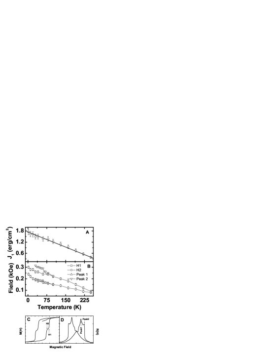
It is to be noted that this equation is for the case where the two FM layers are of equal thickness . The behavior of the magnetization seen in fig.2 corresponds to this situation. In fig.3(a), I have shown the variation of J1 as a function of the temperature calculated using eq. 4 for dYBCO = 500Å. Panel B of fig.3 shows a comparison between the peak position in the MR-H data and the start and end points of the antiferromagnetic phase in MH data. Panels C and D show a typical MH and MR-H data for the sample. The arrows point to positions of the points on the MR-H and MH data which have been plotted in panel B.
I now discuss the behavior of J1 as seen in fig.3(panel A). The temperature dependence of the interlayer exchange coupling in metallic multilayers has been worked out theoretically Edwards ; Brunoprb . The starting point for calculating the coupling is to calculate the energy per unit area in the ferromagnetic and antiferromagnetic configuration. The difference of the two will give the exchange coupling of the system. The energy terms are functions of the reflection coefficients of the electrons in the spacer hitting the spacer-ferromagnet interface calculated in the light of the free-electron model. Using the above method the dependence of linear exchange coupling J1 with temperature is given by Brunoprb
| (5) |
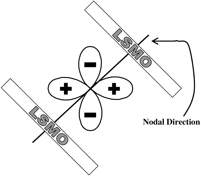
where the characteristic temperature depends on the Fermi wave vector and spacer thickness through the relation , where is the free-electron mass and and are the Planck and Boltzmann constants respectively. In this case, since the transport is along the (110) axis, the relevant wave vector will be . In fig.3 it is seen that increases linearly as the temperature decreases. This is different from the behavior expected from eq. 5. In general, functions of the type x/sinh(x) saturate in the limit x 0, but in this case I do not see any saturation of J1 even at a temperature of 2 K. The magnitude of is almost an order higher than what is seen for (001) oriented heterostructures Senapati . These high values are in line with the predictions of de Melo Melo where he had pointed out that the coupling along the (110) direction will be higher than that along the (100) or (001) directions. In fig.4, I have shown the schematic of a (110) trilayer where the spacer is a -wave superconductor. It is clear from the figure that in this case the coupling, is mediated by the nodal quasiparticles whose number density remains high even at T0. This explains the large J1 and the absence of any anomaly in J1 near Tc. The middle panel of fig.3 shows the comparison between various critical points on the MH loop and MR data. Here I have plotted the starting and end points of the plateau in the MH loop against temperature. From the MR(H) loop, I have taken the points of discontinuity which are indicated in panel D. Panel C shows the position of points H1 and H2 on the MH loop. One can clearly see that both the representative points agree well within experimental error with each other clearly demonstrating the fact that the discontinuities in MR data come from the antiferromagnetic regime of the sample.
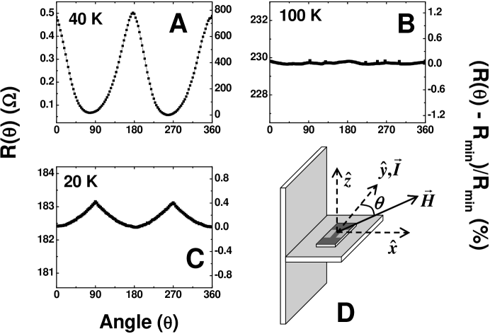
Fig.5 presents the AMR data on (110) trilayers. The x-axis defines the angle with respect to the current direction. The left hand axis shows R and the right hand y-axis shows MR % defined as (R - Rmin)/Rmin where Rmin is the minimum resistance of the sample over the whole range of measurement. The reason for using this definition will be explained when we discuss the data presented in fig. 6. Before I discuss the data in detail, let me explain the measurement geometry which has been schematically shown in panel D of the diagram. The patterned sample is placed over a solid block of copper as shown in the figure. The current in the sample is along ŷ. The applied field rotates in the -plane. The angle is measured with respect to ŷ. The sample is patterned along ŷ in such a way that the CuO2 planes of YBCO are in the -plane. In short, x̂, ŷ and ẑ are parallel to (001), and (110) directions of the sample. Panels A and B show the AMR of the trilayer at T = 40K ( Tc) and T = 100 K ( Tc) respectively on a film with dYBCO = 500 Å. Panel C shows the AMR measurement at 20 K on a film with dYBCO = 200 Å. From panels A & B, one can see that the trilayer shows a huge MR when the SC layer is in the superconducting state. The same film hardly shows any AMR once the film moves into the normal state. This is also evident from the AMR data in panel C. The trilayer in this case is non superconducting for all temperatures (bottom panel of fig.1). The angular dependence in panel C is similar to the one seen for plain LSMO filmsMandal1 . The dependence of AMR in the superconducting state is markedly different from the one in the normal state. For my sample geometry, when the field is perpendicular to the current it is also perpendicular to the CuO2 planes resulting in maximum dissipation in the YBCO layer. So, the logical thing would be that the AMR is higher when the field is perpendicular to the current, but what I see here is completely opposite. This can be explained as follows. We know that the dissipation in YBCO when the applied field is perpendicular to the copper oxide planes is due to the formation of vortices and when the field is parallel, the dissipation is mostly due to pair-breaking effects. In my geometry, the effective area of the sample exposed perpendicular and parallel to field is equal to the thickness of the film times the length and breadth respectively. It is quite possible that the effect of vortex formation in such a small area has lower dissipation than pair breaking effects. Hence, if I assume that pair breaking is causing larger dissipation in the YBCO layer in these trilayers, I can safely conclude that for fields parallel to the current (or copper oxide planes) the AMR will be higher.
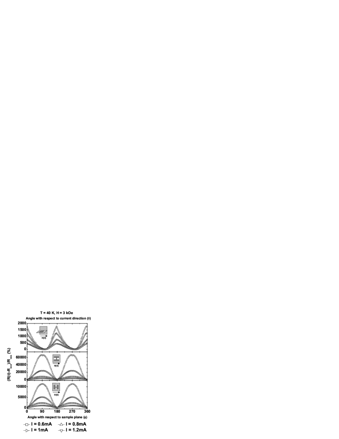
In fig.6, I have plotted the current dependence of the AMR for three different orientations of the sample as shown in the figure. Before I explain the results in this figure it is important to discuss the reasons behind using the particular definition for AMR. If we look closely H(0) in the figure corresponds to the situation when the angle of the field with respect to the current or sample plane is zero. In the top panel, the measurement geometry is the same as is shown in fig.5(d). In the middle panel, the CuO2 planes and current are perpendicular to field when and in the bottom panel the field is parallel to the CuO2 planes and current for H(0). So, to compare the data in these three panels it is important to find a equivalence point for the calculation of AMR which one cannot find if one considers the field orientation or CuO2 plane orientation or current as reference point. So the best option would be to consider the point where the resistance of the sample is minimum. Coming back to the top panel, which shows the dependence in the coplanar configuration, one can see that as current through the sample is decreased AMR increases. For the same film, the middle and bottom panel show unusually large AMR. It is to be noted that the AMR in the middle and bottom panel come due to contributions from two different effects. First will be the AMR due to field being parallel or perpendicular to the CuO2 layer of the SC spacer and the second will be due to the out-of-plane field which gives rise to a high resistance state. In the bottom panel, one can see that the applied field always stays parallel to the CuO2 planes. The AMR seen here essentially arises due to the fact that the applied field becomes perpendicular to SC layer. In the middle panel, one can see that the AMR is much higher than that of any other configuration. In case I assume that the contribution is only from the first case, as pointed out earlier, then there should be no angular dependence in the bottom panel and if I assume that all the contribution is coming from the second case, then the middle and bottom panels should show comparable AMR. The fact that the middle panel shows an AMR almost 6 times that of the bottom panel points to the fact that the AMR is coming from both the contributions which in this case, have same behavior in the configuration shown in middle panel and hence the effect is additive. One can also see that in all the cases, reduction in the current results in an increase in the AMR vindicating the hypothesis that low resistance in the spacer contributes to a higher magnetoresistance. Apart from this, if we try to talk only about the magnitude of change in resistance and not the percentage then we will see that the maximum resistance over the whole range of 2 can increase by as much as 700 times the minimum resistance. The discussion on the trilayers will not be complete without a small discussion on the crystallographic differences along the two directions in the plane of the film. The directions in the plane of the film are and (001) with (001) being the easy axis. The easy axis is predominantly determined by the easy axis of the LSMO layers which in this case is along the (001) directionMandal1 . When the field is along the (001) direction it is the easy axis of the LSMO layers but the dissipative state of the YBCO layer and when the field is along the direction it is parallel to CuO2 layers which is less dissipative but the presence of LSMO layer introduces a strong dissipation resulting in a high resistance state as seen in figures 5 and 6.
III.2 Anisotropic Magnetoresistance of (110) LSMO - YBCO and (110) YBCO thin films.
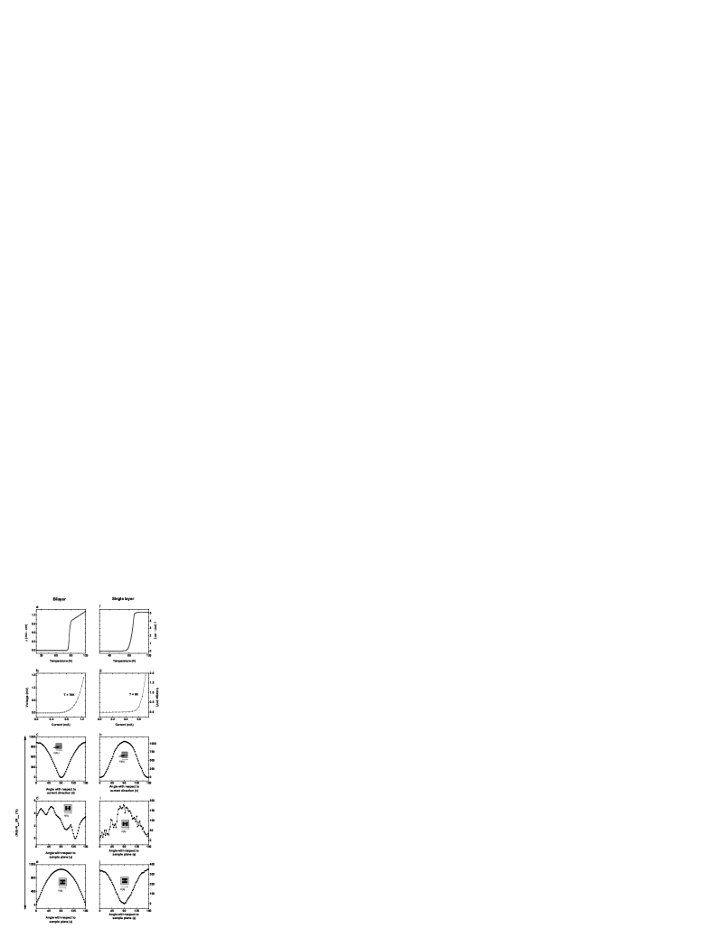
To verify my results of unusually high AMR in the trilayers I have done some control experiments involving an LSMO-YBCO bilayer and a YBCO single layer film. The growth conditions for these films are exactly the same as the trilayer except for the fact that these films were made with dYBCO = 1000Å. Fig.7a shows the resistivity data for the bilayer. Panel b in the same figure shows a current voltage characteristic for the bilayer at 76 K. In fig.7c, d & e, I have shown the AMR in this film at 3 kOe for three different configurations. One can see that AMR in this film is much smaller as compared to that of the superconducting trilayer. Most of the contribution comes from the fact that the field moves from parallel to perpendicular to the CuO2 planes. Panel d shows the AMR when the field stays in the CuO2 plane. The dependence seen here mostly comes from the fact that the field moves in and out of plane of the sample. In fig.7f, I have plotted the resistivity data for a single layer of (110) YBCO. Panel g shows the current voltage characteristic for the film at 6 K. Fig.7h, i & j show the AMR for this film at different configuration. Here one can clearly see that angular dependence comes primarily from the positioning of the field perpendicular or parallel to the CuO2 planes. But a look at panels e and i of the figure tells us that the AMR for the bilayer is higher than that for the single layer. This is explained by the presence of an FM layer near a superconducting layer. Earlier, people had seen a higher change in the resistivity in a bilayer than on a single layer when the film was pushed into the superconducting state Petrashov .
IV Conclusion
In conclusion, manganite - cuprate bilayers and trilayers where the CuO2 planes are normal to the plane of the templated (110) SrTiO3 have been synthesized and their various transport and magnetic properties have been studied. I find that the coupling between the two FM layers is higher in this case than on that of the (001) bilayer as predicted by de Melo Melo . I have also observed unusually high () angular magnetoresistance in these trilayers. Some control experiments have been done to point out the fact that the unusually high AMR comes from the coupling between the two ferromagnetic layers. The MR% calculated from the magnetoresistance measurements shows a peak near the superconducting transition temperature which has been attributed to the unusual increase in the normal state properties of the superconductor near its transition temperature.
Acknowledgements
The author would like to acknowledge financial support from Indian Institute of Technology Kanpur, Kanpur, India.
References
- (1) A. I. Buzdin, Rev. Mod. Phys. 77, 935 (2005)
- (2) F. S. Bergeret, A. F. Volkov and K. B. Efetov, Rev. Mod. Phys. 77, 1321 (2005)
- (3) Yu. A. Izyumov, Yu. N. Proshin and M. G. Khusainov, Sov. Phys. Usp. 45, 109 (2002)
- (4) I. F. Lyuksyyutov and V. L. Pokrovski, Advances in Physics 54, 67 (2005)
- (5) E. A. Demler, G. B. Arnold and M. R. Beasley, Phys. Rev. B 55, 15174 (1997)
- (6) L. R. Tagirov, Physica C 307, 145 (1998)
- (7) A. M. Goldman, V. Vasko, P. Kraus, K. Nikolaev and V. A. Larkin, J. Mag. Mag. Matt. 200, 69 (1999)
- (8) C. L. Chien and Daniel H. Reich, J. Mag. Mag. Matt. 200, 83 (1999)
- (9) I. A. Garifullin, J. Mag. Mag. Matt. 240, 571 (2002)
- (10) R. S. Keizer, S. T. B. Goennenwein, T. M. Klapwijk, G. Miao, G. Xiao and A. Gupta, Nature 439, 825 (2006)
- (11) B. Dieny, V. S. Speriosu, S. Metin, S. S. P. Parkin, B. A. Gurney, P. Baumgart and D. R. Wilhoit, J. Appl. Phys. 69, 4774 (1991)
- (12) A. Chaiken, P. Lubitz, J. J. Krebs, G. A. Prinz and M. Z. Harford, J. Appl. Phys. 70, 5864 (1991)
- (13) P. Bruno and C. Chappert, Phys. Rev. Lett. 67, 1602 (1991)
- (14) G. Binasch, P. Grünberg, F. Saurenbach and W. Zinn, Phys. Rev. B 39, 4828 (1989)
- (15) M. N. Baibich, J. M. Broto, A. Fert, F. Nguyen Van Dau, F. Petroff, P. Eitenne, G. Creuzet, A. Friederich, and J. Chazelas, Phys. Rev. Lett. 61, 2472 (1988)
- (16) A. Barthélémy, A. Fert, M. N. Baibich, S. Hadjoudj, F. Petroff, P. Etienne, R. Cabanel, S. Lequien, F. Nguyen Van Dau and G. Creuzet, J. Appl. Phys. 67, 5908 (1990)
- (17) Z. W. Dong, R. Ramesh, T. Venkatesan, Mark Johnson, Z. Y. Chen, S. P. Pai, V. Talyansky, R. P. Sharma, R. Shreekala, C. J. Lobb and R. L. Greene, Appl. Phys. Lett. 71, 1718 (1997)
- (18) V. Pea, Z. Sefrioui, D. Arias, C. Leon, J. Santamaria, M. Varela, S. J. Pennycook and J. L. Martinez, Phys. Rev. B 69, 224502 (2004)
- (19) K. Senapati and R. C. Budhani, Phys. Rev. B 71, 224507 (2005)
- (20) Soumen Mandal, Saurabh K Bose, Rajeev Sharma, R. C. Budhani, Prahallad Padhan and Wilfrid Prellier, Appl. Phys. Lett. 89, 182508 (2006)
- (21) A. C. Westerheim, Alfredo C. Anderson, D. E. Oates, S. N. Basu, D. Bhatt and M. J. Cima, J. Appl. Phys. 75, 393 (1994).
- (22) S. Mandal, arxiv:0904.0373v1[cond-mat.supr-con], (2009)
- (23) S. Patnaik, Kanwaljeet Singh and R. C. Budhani, Rev. Sci. Instr. 17, 1494 (1999)
- (24) B. Revzin, E. Rozenberg, G. Gorodetsky, J. Pelleg and I. Felner, J. Mag. Mag. Mater. 215-216, 204 (2000)
- (25) Todor Mishonov, Anna Posazhennikova and Joseph Indekeu, Phys. Rev. B 65, 064519 (2002)
- (26) S. O. Demokritov, J. Phys. D 31, 925 (1998)
- (27) D. M. Edwards, J. Mathon, R. B. Muniz and M. S. Phan, Phys. Rev. Lett. 67, 493 (1991)
- (28) P. Bruno, Phys. Rev. B 52, 411 (1995)
- (29) C. A. R. Sá de Melo, Physica C 387, 17 (2003)
- (30) Soumen Mandal and R. C. Budhani, J. Magn. Magn. Mater. 320, 3323 (2008)
- (31) V. T. Petrashov, I. A. Sosnin, I. Cox, A. Parsons and C. Troadec, Phys. Rev. Lett. 83, 3281 (1999)