How wing compliance drives the efficiency of self-propelled flapping flyers
Abstract
Wing flexibility governs the flying performance of flapping wing flyers. Here we use a self-propelled flapping-wing model mounted on a “merry-go-round” to investigate the effect of wing compliance on the propulsive efficiency of the system. Our measurements show that the elastic nature of the wings can lead not only to a substantial reduction of the consumed power, but also to an increment of the propulsive force. A scaling analysis using a flexible plate model for the wings points out that, for flapping flyers in air, the time-dependent shape of the elastic bending wing is governed by the wing inertia. Based on this prediction, we define the ratio of the inertial forces deforming the wing to the elastic restoring force that limits the deformation as the elasto-inertial number . Our measurements with the self-propelled model confirm that it is the appropriate structural parameter to describe flapping flyers with flexible-wings.
Flapping flight is probably the way of locomotion using the most complex dynamics in the animal realm Dudley (2000); Alexander (2004). Structural properties of animal wings, together with wing kinematics, constitute the basic elements of a tough problem: being able to stop, accelerate, execute sharp turning, hover, etc… However, flapping costs a large amount of energy due to the perpetual cycle of acceleration and deceleration involved in the process of generating useful aerodynamic forces Norberg (2002). As a means of minimizing this cost, natural systems have presumably optimized animal wings by tuning their flexibility, which enhances not only their mechanical resistance, but also the animals’ flight efficiency. The crucial nature of the elastic response of the wings in the propulsive performance of a flapping flyer has been made clear not only by observing natural systems Norberg (2002), but also investigating simplified models where wing compliance determines drastic changes in thrust production and efficiency (see Katz and Weihs (1978); Liu and Bose (1997); Prempraneerach et al. (2004); Miao and Ho (2006); Heathcote et al. (2008)). A few ways by which wing flexibility is favorable for both flying animals and man-made devices have recently been proposed Shyy et al. (2008); Vanella et al. (2009); Young et al. (2009) (see also extensive review by Shyy et al. Shyy et al. (2010)). However, although a common hand waving argument is that wing compliance can be beneficial for the flapping flyer if elastic potential energy can be stored when the wings bend and released in a favorable part of the flapping cycle, the details of the balance of fluid dynamical, structural and inertial forces and moments that governs these mechanisms remain not well understood. Experimentally, one has to note that most studies do not consider self-propelled objects but the interaction between flapping bodies held static and an oncoming uniform flow that is driven independently of the flapping motion. If one thinks of cruising flapping flight, the very fact of decoupling the flapping dynamics and the forward speed makes it difficult to extrapolate any conclusions about flight performance to the case of a free flying animal or machine. A notable exception is the experiment by Vandenberghe, Zhang and Childress Vandenberghe et al. (2004), where a heaving wing mounted on an axis free to rotate was shown to spontaneously give rise to a cruising speed perpendicular to the direction of the heaving motion. This work has been recently extended by introducing a pitching degree of freedom to mimic wing compliance Spagnolie et al. (2010).
Here we use an experimental self-propelled flapping-wing model to study the effect of wing flexibility on its propulsive performance. The setup has been designed to enable measurements of the cruising speed, the thrust force, as well as the consumed power, as a function of the imposed wing motion (flapping frequency) and wing design. It is shown that increasing wing flexibility leads
to a substantial reduction of the consumed power as well as an increase of the thrust power, both quantities being directly dependent on the flexural properties of the wings.
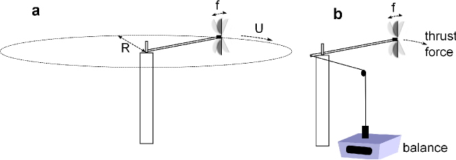
The experimental setup consists of a flapping-wing device that is allowed to turn on a “merry-go-round" type base (in the spirit of le petit manège from Marey Magnan (1934)). The two-wing flapper is attached to a mast that is ball-bearing mounted to a central shaft in such a way that the thrust force produced by the wings makes the flapper turn around this shaft (see figure 1). For the chosen wing geometry (half disk of diameter cm), the control parameters of the experiment are the flapping frequency and the foil chord-wise flexibility (governed by its thickness ). Four pairs of wings were tested, of thicknesses 0.15, 0.23, 0.25 and 0.4 mm that correspond to masses per unit area of 0.20, 0.30, 0.33 and 0.53 kg m-2 and bending rigidities () of 6, 25, 34 and 120 mN m, in the range of the flexural stiffness of real insect wings Combes and Daniel (2003). The natural frequencies of oscillation of the wings measured with relaxation tests are 71, 111, 125 and 166 Hz, respectively. The measured quantities are the power consumption (, computed from voltage and current measurements in series (see also Buchholz et al., 2008)) from which the power of the system running with no wings has been subtracted, the cruising speed of the device ( obtained using the measured time per revolution ) and the thrust force . The force measurement was performed by holding the flapper in a fixed station using a string attached through a pulley to a calibrated weight as shown in figure 1 (top right) and monitoring the weight deficit on a tabletop balance as a function of the flapping frequency. The experiments reported here were performed with flapping frequencies ranging from 10 to 30 Hz, which drove cruising speeds between 0.2 and 1.5 m s-1. Thus, the chord-based Reynolds number (where is the maximum chord and is the kinematic viscosity) ranged between 1000 and 3000 whereas the amplitude-based Strouhal number usually used to characterize flapping-based propulsive systems ranged between 0.3 and 0.9 (using the flapping amplitude at mid-span to define ). These values of and are in the ranges that correspond to flapping flight in nature.
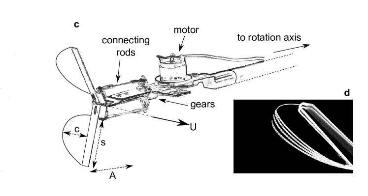
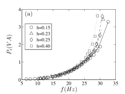
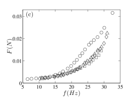
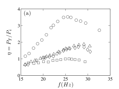
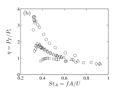
The measurements are summarized in Fig. 2. First, the electrical power consumed by the motor as a function of the flapping frequency is shown in Fig. 2 (a). As can be observed, keeping the system at a certain frequency requires less power as the wings become more flexible. It is also worth noting that the consumed power as a function of the forcing frequency does not change whether the system is running (lines) or not (points), i.e. whether we are measuring the thrust force or the cruising speed. This suggests that the modification of the aerodynamic forces due the the cruising motion does not play a crucial role in the energy needed to perform the flapping. We note that the most flexible wing tested can save up to 60 in consumed power with respect to the most rigid one in the frequency range. Figures 2 (b) and (c) respectively show the cruising forward flight velocity and the thrust force as a function of the input power. Again, for the wing rigidities tested here performance increases with increasing flexibility. In a general way, the present results show that the passive mechanisms associated with wing compliance can increase flight efficiency by increasing the thrust force and the cruising velocity while spending less energy. This efficiency enhancement is summarized in Fig. 3, where the ratio of thrust power to input power is displayed. All measurements are thus combined in this efficiency factor , which has been normalized in the plots with respect to its maximum value for the most rigid wing as . Fig. 3 (a) shows that each wing has an optimum flapping frequency beyond which the efficiency starts to decrease. It is worth noting that this optimum occurs significantly below the natural relaxation frequency so that any conclusion on the role of a resonance to minimize the cost of bending (as discussed for instance in the case of undulatory propulsion by Long and Nipper (1996)) is not applicable (see also Michelin and Llewellyn Smith (2009)). The same efficiency factor is plotted in Fig. 3 (b) with respect to the Strouhal number , where now the position of the optimum decreases with wing flexibility. It occurs on a range between 0.3 and 0.45, which is consistent with the range of optimal Strouhal numbers observed in nature Taylor et al. (2003). The vs. curves show different behaviors depending on the bending rigidity of the wing and prompt us to look for a new scaling including not only aerodynamical variables but also the wing structural parameters.
The first point to address when considering the effect of wing flexibility is to identify the main force that will bend the wing. In the dynamic regime, an elastic flapping wing is subjected to both the fluid dynamic pressure acting on the surface of the wing and the inertia force due to the oscillating acceleration. A measure of the importance of these two bending forces can be given using a simplified model for the flapping wing as a plate of length , mass surface density and bending rigidity (for a plate of thickness and Young’s modulus , ) whose leading edge is heaving sinusoidally with frequency and amplitude . The moment of the mean fluid pressure force scales then as , where is the fluid density and is the maximum flapping velocity, whereas the moment of the inertia force scales as . The ratio of these two moments is actually a mass ratio , which is greater than 10 for all the wings tested in the present case. The main bending factor in this case is thus the inertia force, which will be counterbalanced by the elastic restoring force produced by the bent wing. This is consistent with the analysis by Daniel and Combes (2002) who concluded for most wings moving in air that the feedback between fluid pressure stresses and the instantaneous shape of the wing is negligible with respect to the inertial-elastic mechanisms. The results in Fig. 2 (a) also support this assumption, since the change in the aerodynamic forces in the cruising regime with respect to the fixed station operation of the system is undetectable in the consumed power vs frequency curves. We therefore proceeded to compare the moment of the inertial force to that of the elastic restoring force that scales as . The ratio , which we define as the elasto-inertial number
| (1) |
in terms of the bending length , measures thus to what extent the inertial force due to the oscillating acceleration will be balanced by the elastic resistance to bending (analog definitions of this bending length arise in problems where other forces drive the bending, see for instance Bico et al. (2004); Alben et al. (2002) for capillary and hydrodynamical forces, respectively). This definition determines for instance that for the wing is too rigid for the inertia of the oscillating wing to have an observable effect, or in terms of the bending length, so that no deformation can be observed over the length scale of the wing chord.
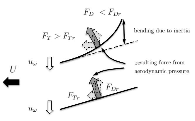
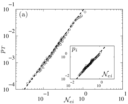
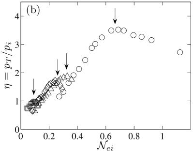
Physically, the form of the bending wing can be seen as a “shape factor” that redistributes the contribution of the aerodynamic forces in both directions -of the flapping motion normal to the wings 111 is the drag force that opposes the flapping motion so that in the standard reference frame, where the thrust force is in the direction of the cruising velocity, it is actually a fluctuating lift force, not to be confused with the drag that limits the cruising velocity. and of the forward displacement- as sketched in Fig 4. During the flapping motion, the wings experience strong drag as they push fluid up and down during a stroke cycle. Because of the flexibility of the wing, the experienced drag scales on a length depending on Alben et al. (2002); Schouveiler and Boudaoud (2006); Gosselin et al. (2010), instead of as it would for the rigid case. On the other hand, the change in shape induces a contribution of the aerodynamic pressure load in the forward direction that is also dependent on the wing bending. The two forces and , respectively normal and in the direction of the cruising speed, should therefore be directly dependent on the wing shape that is determined by the non-dimensional number defined in Eq. 1. This is clearly shown in Fig. 5 (a), where the useful thrust power and the input power are plotted as a function of . The thrust power is defined by the product of the cruising speed and the thrust force (shown in Fig. 2 (b) and (c), respectively), which are rendered non-dimensional using the scalings, and . The non-dimensional thrust power is thus defined as . Fig. 5 (a) clearly shows that all the measured data collapse onto a single power law with . The input power (shown in the inset of Fig. 5 (a)) is non-dimensionalized using the same scaling , and gives a measure of the work of the drag force experienced by the flapping (i.e. ). This quantity also scales with the elasto-inertial number . The efficiency (plotted in Fig. 5 (b) as a function of ) that we have defined previously as is thus a ratio of works: the work of the useful thrust force over the work of the drag force experienced by the flapping wing . A salient feature of the vs. plots in figure 5 (b) is that the main trend followed by the experimental points over different sets of wings is valid only up to a certain threshold for each wing after which the measured data show a change of regime. We have noted in figure 3 that a simple resonance at the relaxation frequency cannot explain the observed behavior. The possible role of subharmonic resonances in the efficiency curves involving a detailed study of the phase dynamics is the subject of ongoing work.
In summary, the effect of wing flexibility on the efficiency of flapping flyers can be thought of as a two-step process: a solid mechanics problem, where the balance between inertial and elastic forces determines the instantaneous shape of the flexible wings, followed by a fluid dynamics problem, where the boundary conditions set by the previous step govern the distribution of aerodynamic forces. This simple passive mechanism, shown here to be well described using the elasto-inertial number , can bring a two-fold advantage: decreasing the energy cost while enhancing the thrust power. The self-propelled system described here gives a framework that should be useful to pursue further studies on the effect of structural and geometrical properties of the wings in the performance of flapping-based propulsion.
Acknowledgements We thank D. Pradal for his help in the design and construction of the experimental setup, J. Bico, B. Roman and O. Doar for discussing the problem and the French Research Agency for support through project ANR-08-BLAN-0099.
References
- Dudley (2000) R. Dudley, The Biomechanics of Insect Flight (Princeton University Press, 2000).
- Alexander (2004) D. E. Alexander, Nature’s Flyers: Birds, Insects, and the Biomechanics of Flight (The Johns Hopkins University Press, 2004).
- Norberg (2002) U. M. L. Norberg, J. Morphology 252, 52 (2002).
- Katz and Weihs (1978) J. Katz and D. Weihs, J. Fluid Mech. 88, 713 (1978).
- Liu and Bose (1997) P. Liu and N. Bose, Proceedings of the Royal Society of London. Series A: Mathematical, Physical and Engineering Sciences 453, 1763 (1997).
- Prempraneerach et al. (2004) P. Prempraneerach, F. S. Hover, and M. S. Triantafyllou, 13th Int. Symp. Unmanned Untethered Submersible Techn., Durham, NH, Aug. 24-27, 2003 (2004).
- Miao and Ho (2006) J. Miao and M. Ho, J. Fluids Struct. 22, 401 (2006).
- Heathcote et al. (2008) S. Heathcote, Z. Wang, and I. Gursul, J. Fluids Struct. 24, 183 (2008).
- Shyy et al. (2008) W. Shyy, Y. Lian, J. Tang, D. Viieru, and H. Liu, Aerodynamics of low Reynolds number flyers, Cambridge Aerospace Series (Cambridge University Press, 2008).
- Vanella et al. (2009) M. Vanella, T. Fitzgerald, S. Preidikman, E. Balaras, and B. Balachandran, J. Exp. Biol. 212, 95 (2009).
- Young et al. (2009) J. Young, S. M. Walker, R. J. Bomphrey, G. K. Taylor, and A. L. R. Thomas, Science 325, 1549 (2009).
- Shyy et al. (2010) W. Shyy, H. Aono, S. Chimakurthi, P. Trizila, C.-K. Kang, C. Cesnik, and H. Liu, Progress in Aerospace Sciences (2010), in press, corrected proof. DOI: 10.1016/j.paerosci.2010.01.001.
- Vandenberghe et al. (2004) N. Vandenberghe, J. Zhang, and S. Childress, J. Fluid Mech. 506, 147 (2004).
- Spagnolie et al. (2010) S. E. Spagnolie, L. Moret, M. J. Shelley, and J. Zhang, Physics of Fluids 22, 041903 (2010).
- Magnan (1934) A. Magnan, La locomotion chez les animaux: I-Le vol des insectes (Hermann & Cie., 1934).
- Combes and Daniel (2003) S. A. Combes and T. L. Daniel, J. Exp. Biol. 206, 2979 (2003).
- Buchholz et al. (2008) J. Buchholz, R. Clark, and A. Smits, Exp. Fluids 45, 461 (2008).
- Long and Nipper (1996) J. H. Long and K. S. Nipper, Amer. Zool. 36, 678 (1996).
- Michelin and Llewellyn Smith (2009) S. Michelin and S. G. Llewellyn Smith, Phys. Fluids 21, 071902 (pages 15) (2009).
- Taylor et al. (2003) G. K. Taylor, R. L. Nudds, and A. L. R. Thomas, Nature 425, 707 (2003).
- Daniel and Combes (2002) T. L. Daniel and S. A. Combes, Integr. Comp. Biol. 42, 1044 (2002).
- Bico et al. (2004) J. Bico, B. Roman, L. Moulin, and A. Boudaoud, Nature 432, 690 (2004).
- Alben et al. (2002) S. Alben, M. Shelley, and J. Zhang, Nature 420, 479 (2002).
- Schouveiler and Boudaoud (2006) L. Schouveiler and A. Boudaoud, J. Fluid Mech. 563, 71 (2006).
- Gosselin et al. (2010) F. Gosselin, E. de Langre, and B. Machado-Almeida, J. Fluid Mech. 650, 319 (2010).