Aiming Perfectly in the Dark - Blind Interference Alignment through Staggered Antenna Switching
Abstract
We propose a blind interference alignment scheme for the vector broadcast channel where the transmitter is equipped with antennas and there are receivers, each equipped with a reconfigurable antenna capable of switching among preset modes. Without any knowledge of the channel coefficient values at the transmitters and with only mild assumptions on the channel coherence structure we show that degrees of freedom are achievable. The key to the blind interference alignment scheme is the ability of the receivers to switch between reconfigurable antenna modes to create short term channel fluctuation patterns that are exploited by the transmitter. The achievable scheme does not require cooperation between transmit antennas and is therefore applicable to the network as well. Only finite symbol extensions are used, and no channel knowledge at the receivers is required to null the interference.
1 Introduction
Bandwidth is a precious resource for wireless networks. How to share this limited resource among multiple users is the primary challenge. A new signal multiplexing approach, called interference alignment, has shown recently that the bandwidth available to each user can be greatly improved [10, 4, 11]. However, there remain very substantial hurdles in translating existing interference alignment schemes to practice. The most significant of these is the issue of channel knowledge. With few exceptions, the interference alignment schemes proposed so far require perfect, and often global, channel knowledge. In a network of distributed nodes, with time-varying channel coefficient values, this is very difficult if not altogether impossible. With this challenge as our motivation, in this work we pursue the goal of blind interference alignment, i.e., we seek to align interference with no knowledge of channel conditions at either transmitters or receivers.
Interference alignment predicates a design of signals so that they cast overlapping shadows at the receivers where they constitute interference while they remain distinguishable at the receivers where they are desired [12]. Finding ways to simultaneously satisfy these seemingly conflicting requirements on signal design has been the principal challenge in interference alignment research. Existing works on interference alignment schemes have looked for increasingly sophisticated mechanisms for aligning interference, especially as the number of users increases. The most powerful state-of-art interference alignment techniques draw upon esoteric results from diophantine approximation theory, e.g., the separability of lattices scaled by rationally independent scalars to fashion interference alignment in seemingly over-constrained settings [14, 15, 2]. Unfortunately, these powerful results also become increasingly fragile in their absolute reliance on infinite precision channel knowledge. The simplest setting where both the sophistication and fragility of state-of-art interference alignment schemes is simultaneously evident is the MISO broadcast channel (BC) with multiple multicasts[2], better known as the compound MISO BC.
A MISO broadcast channel with multiple multicasts, or the compound MISO BC, refers to the setting where the base station transmitter is equipped with transmit antennas and each receiver is equipped with a single receive antenna. There are independent messages intended for groups of receivers, each group consisting of distinct receivers who want the same message. The channel states of all users are globally and perfectly known to the transmitters and recievers. This setting is interesting in its own right as a model for tactical communications and also for commercial applications where, say, mobile subscribers wish to watch one out of different live sports channels, so that each channel is being watched by multiple users. From the perspective of channel uncertainty, it also models the conventional vector BC where we have only receivers, and each receiver’s channel may be in one of different states. While the transmitter knows the possible states, it does not know which one of these states is the actual realization of the users’ channel, and so it must encode the users’ data so that it can be reliably decoded in each of the possible states of that user.
The study of the degrees of freedom for the compound MISO BC was pioneered by Weingarten, Shamai and Kramer in [1]. In this work, it was shown that the multiplexing gain in this setting cannot be more than . It was also conjectured that as the number of users in each group increases, the multiplexing gain will collapse to unity. Recent work in [2, 16] disproved this conjecture and showed that interference alignment is still feasible in the compound vector broadcast channel so that a total multiplexing gain of is achievable regardless of the number users in each group, provided is finite. The surprising result is based on an interference alignment scheme that exploits the separation properties of lattices scaled by rationally independent scalars. Rational independence of channel coefficients is a meaningful concept only when they are known to infinite precision. Thus, the alignment scheme is both powerful in its ability to align interference regardless of the number of users in each group, and also fragile in its fundamental reliance upon the assumption that the transmitter knows all the channel states with infinite precision.
The compound MISO BC with increasing number of alignment constraints (as increases) is analogous to a marksmans’ challenge where one must hit an increasing number of targets with each shot. While the previous conjecture in [1] considered this challenge to be impossible as the number of targets increases, the new result of [2] shows that an extreme marksman (the interference alignment scheme over rational dimensions) is indeed capable of meeting the challenge. However, as one might expect, it turns out that extreme marksmanship requires perfect eyesight – in this case, the ability to separate numbers into rational dimensions with infinite precision.
Continuing the same line of thought, the goal of blind interference alignment, much like aiming perfectly in the dark, may appear impossible. Yet, it has been shown in [3] that in certain scenarios blind interference alignment is not only possible, but also it can be quite simple. For instance, in the context of the MISO BC with antennas at the base station and users, even when the transmitter has no CSIT and the channel coefficients may be drawn from a continuum, [3] showed that if the coherence blocks of the two users are suitably staggered then the outer bound value of DoF is achievable. Moreover, the achievable scheme is a form of repetition coding over a supersymbol consisting of three channel uses.
The supersymbol structure used for blind interference alignment in [3] arises naturally in certain practical settings, e.g., if user 1 has a larger coherence time than user 2, while user 2 has a larger coherence bandwidth than user 1. However, in general , e.g., if the channel coherence does not display any special properties, the problem of blind interference alignment remains open. In this work we address this setting and consider a bolder approach, summarized in the following question –can we artificially manipulate the channel itself to create the opportunities that facilitate blind interference alignment?
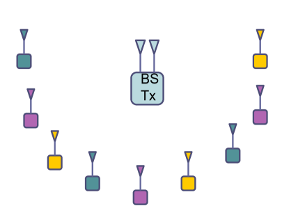
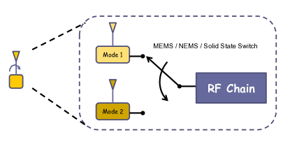
The goal of manipulating the channel naturally leads us to reconfigurable antennas. A reconfigurable antenna is an antenna that can change its characteristics by dynamically changing its geometry. Specifically, the current distribution over the volume of the antenna is changed by switching on and off various geometrical metallic segments (pixels, strips etc.) that constitute the reconfigurable antenna. Each distinct geometrical configuration corresponds to a different mode of operation. Various technologies, such as microelectromechanical switches (MEMS), nanoelectromechanical switches (NEMS) or solid state switches are used to perform the switching operation and offer various tradeoffs in terms of the switching speed, insertion loss, monolithic integration capability, size and reliability[13, 8, 7]. A reconfigurable antenna offers a choice to switch among several pre-set modes. It is more flexible than a single conventional antenna in its ability to switch its radiation pattern among a fixed number of preset modes, and yet it is less flexible than multiple conventional antennas which can be used together with arbitrary beamforming weights to construct logical beams over a continuum of possibilities. For many applications, a single reconfigurable antenna is more desirable than multiple conventional antennas because (1) it needs only one RF chain, and (2) the integrated design of a reconfigurable antenna makes it smaller than multiple conventional antennas. However, the popularity of reconfigurable antennas has been limited by the assumption of fixed preset modes which do not allow continuous adaptability needed for beamforming techniques such as zero forcing, that are typically used to multiplex signals. As a consequence, reconfigurable antennas have heretofore been explored for diversity benefits, but not for multiplexing gain. The focus of research in reconfigurable antenna fabrication has been to create desired radiation patterns. However, in this work we use antenna switching not to direct the beam in a specific direction, but rather to introduce channel fluctuations at pre-determined time instants. More importantly, we will use blind antenna switching, i.e., the antenna switching will not be based on the channel state information at the receivers (CSIR). This relaxed requirement could also simplify the design of the reconfigurable antenna. For our purpose in this work, we ignore the specific hardware aspects and focus instead on the conceptual model of a reconfigurable antenna. At a conceptual level, we model a reconfigurable antenna as capable of switching among independent dumb (isotropic) modes, shown in Fig. 2. Note that the conceptual model is identical to antenna selection.
Consider again the multicast setting. Suppose all the channels are statistically equivalent, follow the same temporal correlation model, and there is no CSIT. This is a worst case scenario and no multiplexing of signals is possible. The total DoF = 1 and time-division, i.e., serving only one group of users at a time, is optimal. Now, let us bring reconfigurable antennas or antenna switching into the picture, so each receiver can switch between two antenna modes. The traditional approach for antenna switching is for each receiver to choose the mode that allows the greatest signal strength for that particular receiver[6, 9]. We call this “selfish” antenna switching. Since all receive antennas are statistically equivalent and they follow the same selfish antenna switching policy, and since the transmitter has no instantaneous CSIT, it is easily seen that the users remain statistically equivalent. In other words, the best the transmitter can do is to transmit to one user at a time and use orthogonal time division across users, so that the total DoF cannot be more than unity. The conventional (selfish) antenna selection approach therefore does not allow any DoF advantage.
The following insight is distilled from [3] and forms the basis for this work - “Instead of each receiver (selfishly) selecting the best reconfigurable antenna mode, if the receivers blindly switch antennas according to a pre-determined signature pattern, then they can artificially create the staggered coherence block structures needed for blind interference alignment”.
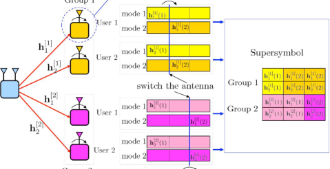
Continuing with the example, suppose each receiver blindly switches from one preset mode to another every two symbols. However the switching instants are staggered. While all receivers in group 1 switch on odd time slots, the receivers in group 2 switch on even time slots. This creates the supersymbol structure shown in Figure 3 which is the key to the blind interference alignment scheme in [3]. Each supersymbol consists of 3 symbols. The channel state of every user in one group (labeled as user 1 in the figure) changes after the first symbol and remains fixed for the last 2 symbols, while the channel state of every user in the other group (user 2 in the figure) is fixed for the first 2 symbols and changes in the last symbol. Once this supersymbol structure is achieved, the staggered coherence block coding (SCBC) scheme proposed in [3] is directly applied to achieve DoF, regardless of the number of receivers in each group. Further, note that this is accomplished without any special assumptions on the channel coherence block structures, except that the coherence time for each user is long enough to span the coding block.
The MISO BC example suggests that staggered antenna switching (SAS) with reconfigurable antennas can be used to translate the staggered coherence block coding schemes of [3] into practice. However, there are important distinctions in terms of what kinds of supersymbol structures can result in the setting of [3] versus our setting in this paper. For example, consider the user interference channel for which an SCBC scheme is proposed in [3] that is capable of achieving DoF. This SCBC scheme is contingent on a very specific temporal correlation model – the cross channels follow the same temporal correlation structure which is different from the direct channels. However, note that antenna switching at a receiver cannot selectively change the channels for some transmitters while keeping the channels from other transmitters to that same receiver unchanged. When we switch a receive antenna, all the channel coefficients associated with that receive antenna will change. Thus, some supersymbol structures possible with the staggered coherent block model of [3] are not possible with staggered antenna switching of reconfigurable antennas. On the other hand, the converse is also true. Staggered antenna switching, because it can follow any complex pattern, allows some supersymbol structures that cannot result simply from staggered coherent blocks. Thus, the staggered antenna switching (SAS) framework that we explore in this paper has a distinct character from the staggered coherence block coding (SCBC) framework considered in [3] and in general neither can be seen as a special case of the other.
We summarize the salient features of the blind interference alignment scheme proposed in this work as follows.
- 1.
- 2.
-
3.
The multiplexing gain achieved with no CSIT for the MISO BC with multiple () multicasts is the same as the maximum possible multiplexing gain with full CSIT for large .
-
4.
The multiplexing gain achieved with no CSIT for the X channel, is the same as the maximum possible multiplexing gain with full CSIT. This is similar to the result in [2].
-
5.
Alignment is achieved by coding over only a finite number of symbols. This is in contrast to [5] where infinite symbol extensions are needed to achieve the outer bound for X channel even with perfect CSIT.
-
6.
No CSIR is needed for the antenna switching pattern used by each receiver.
-
7.
No CSIR is required to null the interference (without losing the desired signal dimensions). While we do not consider non-coherent communication in this paper, the proposed scheme can be directly extended to non-coherent settings with e.g. differential coding schemes.
-
8.
Unlike [3] no special assumptions are needed on channel coherence structure. In fact, except for the antenna switching patterns, the receivers may even be statistically equivalent, i.e., indistinguishable to the transmitter.
2 System model
Consider, as before, the MISO BC with multiple multicasts, where the transmitter has antennas while each receiver is equipped with one reconfigurable antenna (and thus only one RF chain) that can switch among preset modes. Since there is no CSIT, the multiple multicast setting is subsumed under the conventional MISO BC setting where we have a unique receiver for each independent message. We will focus on this latter scenario. The results can be extended easily to the multiple multicast setting by having every receiver in a particular group follow the same strategy as the unique receiver that stands as proxy for this group in the classical MISO BC.
Let be the number of receivers. Further, let us denote the channel vector associated with the preset mode of user ’s reconfigurable receive antenna as where and . We assume that the channel vectors are generic, by which we mean that they are drawn from a continuous distribution (bounded away from zero and infinity to avoid degenerate cases), so that any of them are linearly independent almost surely.
We make no special assumption on the channel coherence block structures, except that the coherence times are long enough so that the channels stay constant across a supersymbol. The supersymbols will be defined later for each .
With the staggered antenna switching scheme, the receivers switch between their antenna modes in a predetermined pattern, so that at time , the mode selected by receiver is , and the resulting channel for user is represented as . Thus, the received signal for the user, at time , is
| (1) |
where is an transmitted signal vector and is the additive white Gaussian noise (AWGN). The channel input is subject to an average power constraint . Unless explicitly stated otherwise, we assume no channel state information at the transmitter (CSIT), i.e., the channel coefficient values are not known to the transmitters. While the blind interference alignment scheme does not require channel state information at the receivers either, i.e., we need no CSIR to either align interference or to null it out at the receiver, we will keep the assumption of perfect CSIR primarily in order to be able to define the degrees of freedom (or multiplexing gain) as the capacity pre-log, and thereby provide us a clean metric for gauging the extent of interference alignment. We will point out the no-CSIR requirement feature of our proposed scheme later on in this paper. While the channel coefficient values are not known, we assume that the switching pattern functions , because they are pre-determined by design (like the codebooks), are known to everyone.
The transmitter sends an independent message with rate to receiver . A rate tuple is achievable if every receiver is able to decode its message with an error probability that can be made arbitrarily small by coding over sufficient channel uses. The closure of the set of all achievable rate tuples is the capacity region . The degrees of freedom metric, , is defined as
| (2) |
3 Blind Interference Alignment for the User MISO BC
We present the main result in the following theorem.
Theorem 1
For the user MISO BC defined in Section 2, a total of DoF are achievable, almost surely.
As mentioned before, the achievable scheme relies on designing an antenna switching pattern for each user and designing a beamforming strategy based on the corresponding temporal correlation structure. The goal is to achieve interference alignment, which refers to the construction of signals in such a manner that they cast overlapping shadows at the receivers where they constitute interference while remain distinct where they are desired. In the following subsection, we first highlight the key to the interference alignment schemes used in this work.
3.1 The Key to Blind Interference Alignment - The Alignment Block
Consider the user MISO broadcast channel defined in Section 2. For simplicity, consider only the transmission of the message for user 1. Suppose multiple symbols are transmitted for user 1. These transmitted symbols for user 1 will cause interference at all other users. Interference alignment means that we would like to keep these symbols distinct at receiver 1, but consolidate them into a smaller subspace at all other receivers. Most importantly, we must accomplish this without any knowledge of the channel coefficients.
Staggered Antenna Switching Pattern: Consider time slots. During these time slots, receiver switches his reconfigurable antenna mode each time to go through all modes. All other receivers, do not switch their antenna modes, i.e., they listen to all transmissions through the same channel. The resulting supersymbol structure is shown in Figure 4.
Beamforming: During time slot , suppose the transmitter sends independent symbols for user , one from each transmit antenna. Now, let the transmitter repeat the same transmission over time slots. In other words, transmit antenna repeats the same symbol a total of times, . The transmitted vector can be represented as:
| (15) |
where is the identity matrix. Note that the beamforming vectors do not depend on the channel values.
With this scheme (ignoring AWGN), the signal received at user 1 is
where , , is the channel vector associated with the preset mode of user 1 and is a zero vector. Since channels are generic, user 1 accesses a full rank MIMO channel almost surely. Thus, the data streams cast an -dimensional shadow at receiver , to achieve DoF.
Now consider the interference at the undesired users .
| (38) |
Since all rows of the effective channel matrix in (38) are the same, its rank is equal to 1. Thus, the symbols intended for user 1 cast only a -dimensional shadow on all undesired receivers, i.e., they align into one dimension. Moreover, notice that they align along the vector , regardless of the channel values. Therefore, even if the receiver does not know the channel coefficients, it can project the received signal into the null space of the all-ones vector to zero force the interference. This is the key to the blind interference cancellation at the receiver mentioned earlier.
We summarize the key to blind interference alignment as follows. If the channel of the desired user changes while that of all undesired users remains fixed over symbols, then the transmitter can send data streams for the desired receiver without knowing all channel values such that these beams remain distinguishable at the desired user while they align into one dimension at all other users.
Note that with such an alignment scheme, interference vectors can be aligned into one dimension. Thus, intuitively the achievable DoF for user MISO BC can be interpreted as follows – Every receiver demands DoF for a total of DoF; at each receiver, the desired signals occupy dimensions while interference streams are aligned into dimensions, for a total of dimensions.
The supersymbol structure shown in Figure 4 will serve as the building block for designing the supersymbol, i.e., antenna switching patterns, for the general user MISO BC. Thus, we refer to it as the alignment block in the following part of this paper. Our goal is to construct the alignment block for each user. Furthermore, with the alignment block, the design of beamforming vectors becomes straightforward. As shown in Figure 4, over the symbols of the alignment block, the beamforming matrix is obtained by stacking the identity matrix times. Finally, the symbols constituting the alignment block may not be necessarily consecutive. In this case, it can be obtained through an interleaving of symbols.
With this insight, we begin with the user MISO BC, go on to user case , and at last solve the general user case.
3.2 User MISO Broadcast Channel
In this section, we consider the user MISO BC where the transmitter is equipped with two antennas and each of receivers has one reconfigurable antenna capable of switching between 2 preset modes. We will show a total of DoF can be achieved. We begin with the 2 user case. Although the solution for this case, as mentioned in the introduction, follows directly from [3], here we use this simplest setting as an example to illustrate how to use the alignment block mentioned in the last section to construct the supersymbol structure. Note that the alignment block for user case consists of two symbols, over which the channel state changes at the desired user while remains fixed at all undesired users.
For the 2 user MISO BC, our goal is to achieve DoF. This can be done by sending two data streams, each carrying one DoF, to each user over three symbol extensions. As a result, in the three dimensional signal space of each user, the desired signals occupy two dimensions, leaving one dimension for the interference. Recall that over one alignment block consisting of two symbols, two data streams can be sent to the desired user while aligned into one dimension at the other user. Thus, if we can construct two alignment blocks within three symbols, one for each user, then interference can be aligned at both users. Moreover, if at each user, the two dimensional space occupied by the desired signals does not overlap with the space occupied by the interference, then our objective is accomplished. With this intuitive understanding, we design the supersymbol as shown in Figure 5. The first two symbols constitute an alignment block for user 1. For user 2, we design the third symbol such that through an interleaving of the first and third symbols, they are converted into an alignment block.
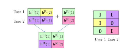
Based on the supersymbol, we can design the beamforming matrix for each user as follows. The beamforming matrix is constructed by stacking three matrices, which is equal to the number of symbols in the supersymbol. The , , block in the beamforming matrix for each user corresponds to the symbol in the supersymbol. For each user, if the symbol belongs to his alignment block, then the corresponding block in his beamforming matrix is a identity matrix. Otherwise, it is a zero matrix. This is illustrated in Figure 5. Since the first two symbols constitute the alignment block for user 1, we place the identity matrix at the first and second blocks but a zero matrix at the third block. For user 2, the first and third symbols constitute an alignment block; thus, we place the identity matrix at the first and third blocks while a zero matrix at the second block.
Such a signaling scheme already guarantees the linear independence of desired signals and the interference at receivers. Notice that at the second time slot, the transmitter only transmits to user 1 and at the third time slot only to user 2. At user 1, the two desired signal vectors do not occupy the third dimension (time slot) in the three dimensional signal space while the interference vector occupies it. Thus, the interference is linearly independent of the desired signals. Similar argument can be applied to user 2. Next, we formalize these ideas through mathematics.
The transmitted signal is
| (49) |
where is a identity matrix. are two independently encoded data streams intended to user , each carrying one DoF. With this scheme, the received signal at user 1 is
| (66) |
where is a zero vector. From (66), it can be easily seen that interference is aligned into one dimension along vector while the desired signals appear through a full rank matrix, and are therefore resolvable. In addition, notice that the third row of the desired signals is zero, while that of the interference vector, , is 1. Therefore, any linear combination of the desired signals leads to zero in the third row, ensuring linear independence among them. Similar argument can be applied to user 2, so that he is able to achieve 2 DoF as well. Thus, 4 DoF can be achieved over 3 symbol extensions, so that (normalized) DoF are achieved.
Remark: From equation (66) note that user 1 can cancel the interference due to user 2 by simply subtracting the third received symbol from the first. This operation does not require any knowledge of channel coefficient values at the receiver and produces an interference-free signal while leaving the desired signal unaffected, although the noise is doubled over the first symbol. The blind interference cancellation property is common to all the blind interference alignment schemes proposed in this paper.
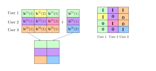
Now let us consider a 3 user MISO BC. For this case, we need to show DoF can be achieved. This can be done by achieving 2 DoF for each user over 4 symbol extensions. Following similar analysis as two user case, we can design the supersymbol consisting of 4 symbols such that three alignment blocks, one for each user, are created. Then each user transmits two data streams over its alignment block so that they occupy two dimensions at the desired receiver’s signal space while aligning into one dimension at all other receivers. Thus, within each user’s four dimensional signal space, the desired signals occupy two dimensions while the interference from each interferer occupies one dimension for a total of two dimensions. The supersymbol structure is shown in Figure 6. Note that the first 3 symbols as the same as for the 2 user case. The fourth symbol is designed such that when combined with the first symbol, an alignment block is created for user 3. With the same mapping from the supersymbol to the beamforming vectors as the two user case, the beamforming matrix is
| (71) |
where is the identity matrix and is the zero matrix. The , , block column is for user . With interference aligned, it remains to check that desired signals do not overlap with the interference at each receiver. Again, this is guaranteed by orthogonality among signals over last three time slots, leading to linear independence among them in the four dimensional signal space at each receiver. To see this, let us consider user 1. The interference from user 2 is aligned along vector and the interference from user 3 is aligned along the vector . Thus, we need to show that the following matrix is full rank.
| (76) |
This can be easily verified from the third and fourth rows. By similar arguments, it can be shown that desired signals are linearly independent with the interference at user 2 and 3.
Remark: Once again, it is easily verified that each user can cancel all interference without the need for channel coefficient knowledge at the receivers. This is done, e.g., at user 1, by subtracting the third symbol from the first (to eliminate interference from user 2) and by subtracting the fourth symbol from the first (to eliminate interference from user 3), thus leaving only an interference-free desired signal over symbols 1 and 2, albeit with the cost that the noise is now three times stronger for symbol 1. The property of blind interference cancellation at the receivers makes the blind interference alignment schemes in this work ideal for non-coherent communication, i.e., with no CSIR, through differential coding schemes which only require coherence over relatively small intervals.
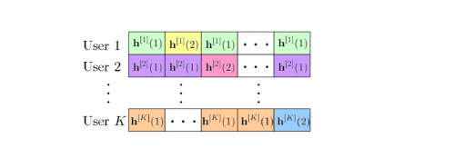
With the understanding of 2 user and 3 user cases, we are ready to consider the general user MISO BC. In general, the supersymbol structure is shown in Figure 7. The supersymbol consists of symbols. Each user’s channel state only comes from one of two channel values corresponding to channels associated with two reconfigurable modes of each receiver’s reconfigurable antenna. For user , , the channel state over the first symbols maintains the first value, it changes to the other value at the symbol and changes back to the first value at the symbol and remains fixed until the end of the supersymbol. With this structure, user can obtain its alignment block through an interleaving of symbols at the first time slot and the time slot. Over each alignment block, two data streams, each carrying one DoF, are transmitted to its corresponding user while remaining aligned into one dimension at all other users. According to the supersymbol structure, the beamforming matrix can be obtained as follows
| (82) |
The block column carries two DoF for user . With this scheme, at each user, the desired signals occupy 2 dimensions in the dimensional signal space while all interference occupies dimensions, one from each interferer. It remains to show that at each user, the desired signals and interference are linearly independent. This is guaranteed by the orthogonality among signals over the last symbols. At , time slot, the transmitter only transmits signals to user . Recall the interference from user is aligned into one dimension at all other users. Therefore, only this interference vector occupies the dimension in the dimensional signal space, leading to its linear independence with desired signals and all other interference. Thus, at each user, all interference is linearly independent with the desired signals. As a result, each user can achieve 2 DoF, for a total of DoF, over symbol extensions. Thus, DoF are achieved.
3.3 User MISO BC
When the number of antennas at the transmitter increases to 3, the alignment problem is more challenging. However, the key idea, as before, is to construct alignment blocks for each user. Note that the alignment block for any user in the MISO BC is comprised of three symbols, over which the that user’s channel changes while the channel of all other users remains fixed. Thus, over the alignment block, three data streams can be separated at the desired user while remaining aligned into one dimension at all other users. We begin with the 2 user case.
3.3.1 2 User MISO BC
We need to show DoF are achievable. This can be achieved with 8 symbol extensions, over which each user achieves 6 DoF, for a total of 12 DoF. Each user’s 6 beams can be sent over two alignment blocks, 3 for each alignment block, so that they can be aligned into two dimensions at the other receiver, leaving the remaining 6 dimensions for the desired signals. The supersymbol consisting of 8 symbols is shown in Figure 8. As we can see, the first 6 symbols constitute two alignment blocks for user 1. On the other hand, two alignment blocks for user 2 can be obtained by adding 2 additional symbols and through an interleaving of symbols as shown in Figure 8. It is important to note that for each user, two alignment blocks do not overlap with each other. Thus, signals sent over two alignment blocks are orthogonal in time. As a result, 3 beams sent over one alignment block are orthogonal to the other 3 beams sent over the other alignment block, ensuring 6 beams can be separated at the desired user.
With the supersymbol structure, we can design the beamforming matrices. Similar to the 2 user case, the beamforming matrix for each user can be obtained according to the alignment block. Different from the 2 user case, where each user has only one alignment block, here each user has two alignment blocks. In this case, each user’s beamforming matrix consists of two block columns, each corresponding to one alignment block. Each block column can be designed following the same mapping used in the two user case as illustrated in Figure 8. With these beamforming vectors, the transmitted signal is
where is the identity matrix and is a zero matrix. , , , is the independently encoded data stream, carrying one DoF, for user . The channel matrix is a block diagonal matrix with the diagonal block corresponding to the symbol in the supersymbol. Thus, the channel matrix of user 1 is
Then, the received signal at user 1 is
| (113) |
It can be easily seen that the interference is aligned into two dimensions, spanned by two columns and . For the desired signals, since each block column has rank 3 and two block columns are orthogonal to each other, the total rank is equal to 6. It remains to check that the 6 dimensions occupied by the desired signal are linearly independent of the two interference dimensions. This is true due to the orthogonality among signals in the seventh and eighth dimensions. Thus, user 1 is able to achieve 6 DoF. Similar arguments can be used for user 2, so that 6 DoF are achieved for him as well.
So far, we have seen two problems that we need to consider and the ideas used to solve them. One is the alignment problem and the other is the linear independence issues. The alignment problem can be solved by constructing non-overlapping alignment blocks for each user. Linear independence issues include linear independence of the desired signals at the desired receiver, and their independence with the interference. For the desired signals, we already see that the signals transmitted over one alignment block are linearly independent. The linear independence of data streams transmitted across different alignment blocks is guaranteed by orthogonality among alignment blocks in time. For the linear independence between desired signals and the interference, it is ensured by orthogonality of signals in the last symbol of each alignment block. Notice that in the last symbol of each alignment block, only the signal sent over this alignment block is active. Thus, after being aligned into one dimension, the interference vector is linearly independent with all other signals.
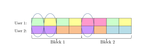
To make things systematic, we can change the order of symbols in the supersymbol and their corresponding rows in the beamforming matrix. The goal is to separate the alignment problem and linear independence issues. In particular, we group last symbols of all alignment blocks into a block which we refer to as Block 2 as illustrated in Figure 9. The remaining part is called Block 1. Basically, Block 1 ensures alignment, while Block 2 guarantees desired signals do not overlap with interference. After reordering, the corresponding beamforming matrix for 2 user case is as follows:
| (122) |
We can argue that once Block 1 is designed, Block 2 can be determined automatically. Note every symbol in Block 2 can be grouped with two symbols in Block 1 as an alignment block. In addition, over an alignment block, the channel state of the desired user changes while that of all undesired users remains fixed. Thus, for the desired user, the last symbol of the alignment block is set to be the third channel value. For all other undesired users’ channels, they are set to be the same as the channel in previous symbols of that alignment block. This is illustrated in Figure 9 where three symbols constituting one alignment block for user 1 are circled. Notice that once the two symbols are determined in Block 1, the third one in Block 2 is determined uniquely. As a result, we now only need to design the channel structure in Block 1. Once designed, Block 2 can be determined automatically.
3.3.2 Structure of Block 1 and Design of Beamforming Vectors
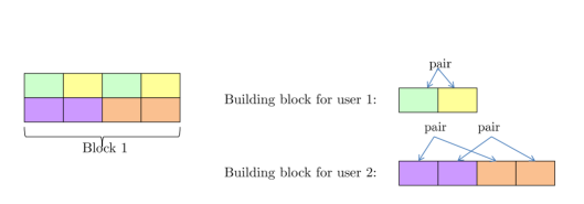
In this section, we will show how to design Block 1 of the supersymbol for user MISO BC and how to design the beamforming vectors at the transmitter based on Block 1. To understand the structure of Block 1, we first consider the 2 user MISO BC. Block 1 is shown in Figure 10. First note that in Block 1, since there is no third symbol of the alignment block, only two different channel values for each user are needed. In addition, symbols in Block 1 are periodic with the building blocks shown in Figure 10. As we can see, the building block of user 1 consists of symbols while that of user 2 consists of symbols. Since Block 1 consists of 4 symbols, user 1 has two building blocks while user 2 has only one building block. To design the beamforming vectors, we can pair the time slots with two different channel values within every building block of each user as shown in Figure 10 to constitute the first two symbols of the alignment block .
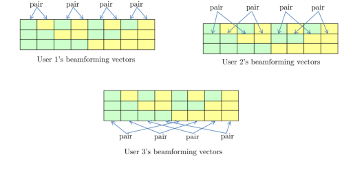
In general, if there are users, then Block 1 consists of symbols. Each user’s channel states are periodic in Block 1 with the building block shown in Figure 11. Note that for simplicity, we use the same color to denote the channel for different users. However, this does not mean that channel values at different users are the same. In fact, they are different with probability one. As we can see, the building block of user is comprised of two sub-blocks, each with length , for a total of symbols. The channel state remains fixed within each sub-block while it changes across different sub-blocks. The channel state in the , , sub-block corresponds to the channel vector associated with the preset antenna mode at the user. To obtain the temporal correlation signature for user in Block 1, we can simply repeat its building block times. In other words, there are building blocks for user in Block 1.
To design the beamforming vectors for user , we can pair the , symbol in one sub-block with the one in the other sub-block within one building block as shown in Figure 11. Since there are building blocks, a total of pairs can be created. It can be verified these pairs satisfy the requirement of the alignment block. Detailed explanations are deferred to next section where the general user MISO BC is considered.
With this construction, we can calculate the achievable DoF. First let us consider the number of symbols in Block 2. In Block 1, each user has pairs. Since each pair needs one symbol in Block 2 to constitute one alignment block, a total of symbols are needed in Block 2. Therefore, the total number of symbols in the supersymbol is . On the other hand, 3 beams can be transmitted over one alignment block for the desired user while aligned into one dimension at all other users. Since each user has alignment block, at the dimensional receiver’s signal space, dimensions are occupied by the desired signals while the remaining dimensions are occupied by the interference. Since signals are orthogonal in Block 2, desired signals do not overlap with the interference. Therefore, the normalized DoF is .
Next, we take the 3 user MISO BC as an example to illustrate the points mentioned in this section.
3.3.3 Example: 3 User MISO BC
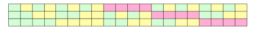
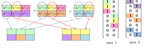
Let us first consider Block 1. For three users, Block 1 consists of symbols. The building blocks for user 1, 2 and 3 are shown in Figure 11. Therefore, there are 4, 2 and 1 building blocks for user 1, 2 and 3, respectively. Block 1 is illustrated in Figure 12, in which the pairing for each user is also shown. It can be seen that for each user, the channel in two time slots of each pair changes at the desired user while it remains the same at the undesired users, as required by the alignment block. After adding Block 2, the complete supersymbol structure for 3 user case is shown in Figure 13. The beamforming matrices for user 1, 2 and 3 can be easily obtained through the supersymbol structure as
3.4 User MISO Broadcast Channel
In this section, we consider the general user case and show how to systematically design the supersymbol structure and the beamforming matrix. This consists of three steps.
Step 1: Design Block 1
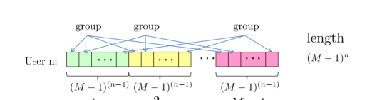
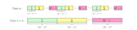
Block 1 consists of a total of symbols. Each user’s channel state switching pattern is periodic in Block 1 with the building block shown in Figure 14. As we can see, the building block of user is comprised of sub-blocks, each with length , for a total of symbols. The channel state remains fixed within each sub-block while it changes across different sub-blocks. The channel state in the , , sub-block corresponds to the channel vector associated with the preset antenna mode at the user. To obtain the temporal correlation signature for user in Block 1, we can simply repeat its building block times. In other words, there are building blocks for user in Block 1.
In general, each user’s temporal correlation can be described by a function of time whose values come from all the possible channel values he can take. Let us define the function of time for user as whose value is drawn from the set where , , denotes the channel vector associated with the mode of user ’s receive antenna. Then we can denote the channel of Block 1 for user as
| (130) |
Note that for Block 1, , since the length of Block 1 is .
Step 2: Design Beamforming Matrices
With Block 1 designed, we can now design the beamforming vectors. As mentioned before, the key is to create non-overlapping alignment blocks for each user. Each alignment block corresponds to one block column in the beamforming matrix, which is obtained by stacking the identity matrix at the rows corresponding to the symbol instants of the alignment block.
Note that in Block 1, there are distinct symbols for each user. Therefore, we will construct the first symbols, which are referred to as a group, of the alignment block. The last symbol for each alignment block is provided in Block 2. Now consider user . Recall that the channel state of the desired user changes over an alignment block. Therefore, we can group the symbol in each of sub-blocks within one building block as shown in Figure 14. Since there are symbols in one sub-block, a total of groups can be created from one building block. Mathematically, within each building block, the group consists of following symbols:
| (131) |
Such grouping is repeated within each building block for a total of building blocks for user . Mathematically, we can represent the group in the building block as
| (132) |
Note that is the length of one building block.
We need to check that each group satisfies the requirement of the alignment block, i.e., the channel state of the desired user changes while that of all other users remains constant in each group. Note that (3.4) specifies the time instants of symbols for each group, and (130) describes how channel changes with time for every user. Therefore, we can use (130) to verify how channel state changes at each user during the time instants of each group given in (3.4). Consider user . Let us first verify that the channel state changes at the desired user, i.e., user . Note that the group in the building block is given in (3.4). Now we calculate the channel values in these time slots by (130). It can be easily seen that the remainders of these time slots divided by are as follows
| (133) |
Therefore, according to (130), the channel values at these time slots are . In other words, the channel state changes as required. Now let us consider user . The channel state should remain fixed for each group. Notice that the remainders of each group’s time slots divided by are the same, i.e., . From (130), if the remainders are the same, the channel state is fixed. Now consider user . Notice that the length of sub-blocks of user is , which is no smaller than , the length of the building block of user . In addition, channel of user remains fixed within each sub-block. Thus, as long as symbols in each group of user belong to the same sub-block of user , then the channel state they see at user is the same. Recall that each group is created within every building block of user . Therefore, if the boundary of the building block of user is aligned with that of sub-block of user , then each group is within the same sub-block at user . This can be easily verified since the length of the sub-block of user , , is an integer multiple of that of the building block of user , . For example, as illustrated in Figure 15, the building block of user is of length which is equal to the length of one sub-block of user . The channel remains constant within a sub-block of user . Therefore, all groups within a building block of user see the same channel value at receiver . As a result, all groups satisfy the requirement of the alignment block structure.
Step 3: Design Block 2
Once Block 1 is designed, Block 2 can be easily determined. Recall that in Block 1, we create the first symbols of the alignment block. Therefore, in Block 2, each symbol serves as the last symbol for each group in Block 1 to create one alignment block. Since for each user, there are groups, a total of symbols are needed for users in Block 2. Now we can determine the channel values in Block 2. We divide Block 2 into sub-blocks, one with length . In sub-block , we provide the last symbol for user . Therefore, user ’s channels are equal to in sub-block . For all other users, each of symbols in sub-block is set to be equal to the value of its corresponding group. As we have shown before, each group’s channel remains fixed at the undesired user. Thus, to determine each symbol in sub-block for user , we can find the first time instant of its corresponding group in Block 1, then set it to be equal to the channel value at that time instant. From (3.4), we can see that the first time instant of the group in the building block for user is
| (134) |
Therefore, user ’s channel in the sub-block in Block 2 is equal to .
With this scheme, each user achieves DoF over symbol extensions. Therefore, the normalized total DoF is equal to .
Remark: Note that the beamforming strategy does not require cooperation among antennas. Thus, the same achievable schemes derived for user MISO BC can be directly applied to the channel where there are transmitters and receivers. Each transmitter has a message for each receiver for a total of messages in the network.
4 Achievable Rates for the User MISO BC with Zero-Forcing Interference at the Receiver
In this section, we derive a closed form expression for the rate achieved using the blind interference alignment scheme designed in last section and with zero-forcing interference at the receiver. The result is presented in the following theorem.
Theorem 2
For the user MISO BC defined in Section 2, the achievable sum rate with zero-forcing interference at each user, is
| (135) |
where
| (141) |
Since interference alignment is achieved perfectly within a finite number of symbol extensions, the sum rate provides a capacity approximation within . In other words, the approximation error is bounded by a constant as SNR goes to infinity. We can approximate the achievable rate at high SNR as follows.
| (142) | |||||
where
| (148) |
Proof: We begin with the 2 user case. Due to symmetry, let us consider user 1. The received signal at user 1 is given by (66). The interference is aligned along . To zero-force the interference, we need to project the received signal onto a 2 dimensional subspace that is orthogonal to . It can be seen that rows of the following matrix form an orthonormal basis of this subspace.
| (151) |
Thus, after projection, the signal is
| (156) |
where is the noise, still white, after the projection. Thus, receiver 1 accesses a full rank MIMO channel. Essentially, what the zero forcing receiver does is using the interference received over the last time slot of each alignment block to cancel the interference received in previous time slots in that alignment block. Since there is no CSIT, we allocate equal power to each data stream, i.e., per data stream such that the average power constraint over three time slots is satisfied. Thus, the achievable rate for user 1 per time slot is
| (157) |
Due to symmetry, user 2 is able to achieve
| (158) |
where
| (161) |
For the user MISO BC, from (82), it can be seen that at user 1 the subspaces occupied by the desired signal and interference are spanned by the first two columns and the last columns of the following matrix, respectively.
| (167) |
It can be seen that the rows of the following matrix form an orthonormal basis of the subspace orthogonal to the subspace spanned by interference.
| (170) |
After projection, the signal is
| (175) |
With equal power allocation to each data stream and under the average power constraint, user 1’s rate is
| (176) |
Due to symmetry, user can achieve a rate
| (177) |
where
| (180) |
Now let us consider the 2 user case. Different from the user case, each user has more than one alignment block. Recall that alignment blocks are orthogonal with each other. Thus, we can decode signals sent over different alignment blocks separately. Consider the received signal at user 1 which is given by (113). Since two block columns are orthogonal, we can first decode the signals along the first block column by discarding three dimensions occupied by the desired signal along the second block column in the received signal space. Therefore, in the remaining 5 dimensional subspace of the 8 dimensional signal space, the desired signals are along the first three columns and the interference are along the last two columns of the following matrix.
| (186) |
The projection matrix is
| (190) |
After projection, the signal is
| (197) |
Thus, the rate for three data streams over 8 symbol extensions is
| (198) |
Due to symmetry, the rate for the other three data streams transmitted over the other alignment block is the same. Therefore, 2 can be achieved over 8 symbol extensions. Thus, the normalized rate is
| (199) |
By similar argument, we can obtain user 2’s rate by changing the user index 1 into 2.
For general user case, to decode data streams over one alignment block, we can discard dimensions occupied by all desired signals transmitted over all other alignment blocks since they are orthogonal in time. For interference, we can use the interference signal received over the last symbol of each alignment block to cancel interference received over previous symbols in that alignment block. Because the interference is the same over all symbols of each alignment block due to repetition coding and interference is orthogonal over the last symbol of all alignment blocks. Mathematically, it can be shown that for user , the first block column corresponding to columns of the following matrix spans the subspace occupied by the desired signal in one alignment block while the last columns span the subspace occupied by the interference.
| (206) |
where is the identity matrix, is the zero matrix, and
| (211) |
Thus, the projection matrix is
| (214) |
Then the received signal after zero forcing is
| (224) |
With equal power allocation to each data stream, the rate achieved for data streams in one alignment block is
| (225) |
Since there are a total of alignment blocks, and a total of time slots, the normalized rate for user is
| (226) | |||||
| (227) |
5 Conclusion
Recent work has shown that channel correlations can be exploited to achieve interference alignment even when the transmitter has no information about the exact channel values [3]. This work shows that channel temporal correlations required in [3] can be created, and thus interference alignment can be achieved in practice. The idea is to manipulate channels through antenna selection. By switching antennas during transmission, different temporal correlations can be created at different users. With these new insights, we provide a systematic way to achieve blind interference alignment for the user MISO BC, possibly with multicast traffic so that the outer bound of DoF is achieved. The coding scheme is essentially a simple repetition code over a finite number of symbols. The key to the blind interference alignment is that multiple symbols that follow the same repetition code are automatically aligned into one dimension and can only be separated through short term channel fluctuations. Thus the key is to introduce these short term channel fluctuations at the correct time instants to un-align the desired symbols without disturbing the alignment of the interfering symbols. The simplicity of the coding scheme allows us to write closed form achievable rate expressions at any SNR. While the assumption of perfect CSIR allows us to use the DoF metric and write closed form rate expressions, CSIR is not not needed to cancel interference. This feature makes the schemes proposed in this work suitable for non-coherent communications, i.e., with no CSIR, in combination with differential coding schemes that require coherence over relatively short intervals.
In this paper we focus only on blind interference alignment schemes that exploit receive antenna selection. This does not imply that transmit antenna selection is never useful. Indeed, the two user MIMO interference channel blind interference alignment example presented in [3] is easily seen to be possible through antenna switching only at one transmitter. In addition, we only consider the broadcast channel and channel in this paper. In fact, antenna switching can be useful in other networks as well. For example, with antenna switching, the user interference channel with constant channel coefficients can achieve more than one DoF. For example, the 4 user interference channel has at least DoF using configurable antenna at the receiver. This can be seen by converting the channel into 2 interfering MAC channels. In each MAC channel there are two transmitters each sending one message to the receiver and causing interference to the receiver in the other MAC channel. Now, replicate each receiver twice to create a receiver for each transmitter, these receivers are statistically equivalent, hence each is equivalent to the MAC receiver. As a result, it is converted into a 4 user interference channel that achieves DoF. Exploiting SCBC schemes for other wireless network is also an interesting avenue for future work.
References
- [1] H. Weingarten, S. Shamai and G. Kramer, “On the compound MIMO broadcast channel”, Information Theory Workshop, Jan. 2007
- [2] T. Gou, S. Jafar and C. Wang, “On the Degrees of Freedom of Finite State Compound Wireless Networks - Settling a Conjecture by Weingarten et. al”, arXiv:0909.4177, 2009.
- [3] S. Jafar, “Exploiting Channel Correlations - Simple Interference Alignment Schemes with no CSIT”, arXiv:0910.0555, 2009.
- [4] B. Nazer, M. Gastpar, S. A. Jafar, and S. Vishwanath, “Ergodic Interference Alignment,” Proceedings of the IEEE International Symposium on Information Theory (ISIT 2009), Seoul, Korea, June 2009.
- [5] Viveck R. Cadambe, Syed A. Jafar, “Interference Alignment and the Degrees of Freedom of Wireless X Networks”, IEEE Transactions on Information Theory, Vol. 55, No. 9, Sep. 2009,Pages: 3893-3908.
- [6] A. F. Molisch and M.Z. Win, “ MIMO Systems with Antenna Selection”, IEEE Microwave Magazine, March 2004.
- [7] G.M Rebeiz, “ RF MEMS switches: status of the technology”, 12th International Conference on Solid-State Sensors, Actuators and Microsystems, June, 2003.
- [8] P. Sudarshan, N.B. Mehta, A.F. Molisch and J. Zhang, “Antenna selection with RF pre-processing: robustness to RF and selection non-idealities”, IEEE radio and wireless conference, Sept. 2004.
- [9] S. Sanayei and A. Nostratinia, “ Antenna Selection in MIMO Systems”, IEEE Communications Magazine, Octorber 2004.
- [10] V. Cadambe and S. Jafar, “Interference alignment and the degrees of freedom of the user interference channel”, IEEE Trans. on Information Theory, vol. 54, pp. 3425–3441, Aug. 2008.
- [11] S. Jafar, “The Ergodic Capacity of Interference Networks”, arXiv:0902.0838, Feb. 2009.
- [12] S. Jafar, S. Shamai, “Degrees of Freedom Region for the MIMO Channel”, IEEE Trans. on Information Theory, vol. 54, No. 1, pp. 151-170, Jan. 2008.
- [13] Bedri A. Cetiner, Necmi Biyikli, Bahadir S. Yildirim, Yasin Damgaci, “Nanoelectromechanical switches for reconfigurable antennas”, Microwave and Optical Technology Letters, Vol 52, Issue 1, pp. 64-69, Nov. 2009.
- [14] R. Etkin and E. Ordentlich, “On the Degrees-of-Freedom of the -User Gaussian Interference Channel”, http://arxiv.org/abs/0901.1695, Jan. 2009.
- [15] A.S. Motahari, S. O. Gharan and A. K. Khandani, “Real Interference Alignment with Real Numbers,” http://arxiv.org/abs/0908.1208, Aug. 2009.
- [16] M.A. Maddah-Ali, “On the Degrees of Freedom of the Compound MIMO Broadcast Channels with Finite States”, arXiv:0909.5006v3, Oct. 2009.