Disentangling the effects of spin-orbit and hyperfine interactions on spin blockade
Abstract
We have achieved the few-electron regime in InAs nanowire double quantum dots. Spin blockade is observed for the first two half-filled orbitals, where the transport cycle is interrupted by forbidden transitions between triplet and singlet states. Partial lifting of spin blockade is explained by spin-orbit and hyperfine mechanisms that enable triplet to singlet transitions. The measurements over a wide range of interdot coupling and tunneling rates to the leads are well reproduced by a simple transport model. This allows us to separate and quantify the contributions of the spin-orbit and hyperfine interactions.
pacs:
73.63.Kv,72.25.-bSpins in semiconductor quantum dots are possible building blocks for quantum information processing Loss and DiVincenzo (1998). The ultimate control of spin states is achieved in electrically defined single and double quantum dots Hanson et al. (2007). Many semiconductors that host such dots exhibit strong spin-orbit and hyperfine interactions. On the one hand, these interactions provide means of coherent spin control Nowack et al. (2007); Foletti et al. (2009). On the other hand, they mix spin states. In double quantum dots, mixing of singlet and triplet states weakens spin blockade Koppens et al. (2005); Johnson et al. (2005a); Pfund et al. (2007a, b); Churchill et al. (2009), which is a crucial effect for spin qubit operation Petta et al. (2005); Koppens et al. (2006). Spin mixing due to hyperfine interaction was studied in GaAs double quantum dots, where spin-orbit coupling is weak Koppens et al. (2005); Johnson et al. (2005a); Jouravlev and Nazarov (2006). In InAs, besides the hyperfine interaction, also spin-orbit interaction has a considerable effect on spin blockade. Previous measurement on many electron double dots in InAs nanowires demonstrated that spin blockade is lifted by both interactions Pfund et al. (2007a, b). However, the effects of these two interactions could not be separated. As a consequence, the exact determination of the spin-orbit mechanism was lacking.
In this Letter we establish the individual roles of spin-orbit and hyperfine interactions in the spin-blockade regime. Spin blockade is observed in tunable gate-defined few-electron double quantum dots in InAs nanowires. In the few-electron regime, the quantum states involved in transport can be reliably identified. This enables a careful comparison to a theory which includes random nuclear magnetic fields as well as spin-orbit mediated tunneling between triplets and singlets Danon and Nazarov (2009). The effects of the two interactions are traced in three distinct transport regimes, determined by the interdot coupling and the tunneling rates to the leads. The regimes are observed in two few-electron nanowire devices, results from one of them are discussed in the paper.
The nanowire devices are fabricated on pre-patterned substrates, following Ref. Fasth et al. (2007) (Fig. 1, upper inset). The substrates are patterned with narrow metallic gates which are covered with a 20 nm layer of Si3N4 dielectric to suppress gate leakage Buizert et al. (2008). Single-crystalline InAs nanowires with diameters from 40-80 nm are deposited randomly on the substrate. Conveniently aligned wires are contacted by source and drain electrodes. Simultaneously, contacts are made to the gates underneath the wire. Measurements are performed at mK in a magnetic field applied perpendicular to the substrate.
The few-electron double quantum dot is formed by gates 1-4. Such tuning ensures that both dots can be emptied before the barriers become too opaque for detecting current. Gates 1 and 4 define the outer barriers, gates 2 and 3 control the interdot coupling. The charge stability diagram of a double dot is obtained by sweeping gates 2 and 3 and monitoring the source-drain current (Fig. 1). The empty (0,0) state is verified by Coulomb blockade measurements: no lower charge states are observed in either dot up to mVvan Tilburg et al. (in preparation). Large charging and orbital energies extracted from the last Coulomb diamond also support the few electron regime ( meV, meV)Fasth et al. (2007). In both dots the energy to add the third electron () is higher than the energy to add the second or the fourth (), see Fig. 1. This indicates that the first few orbitals are doubly-degenerate due to spin.
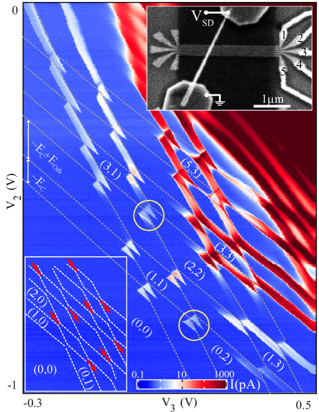
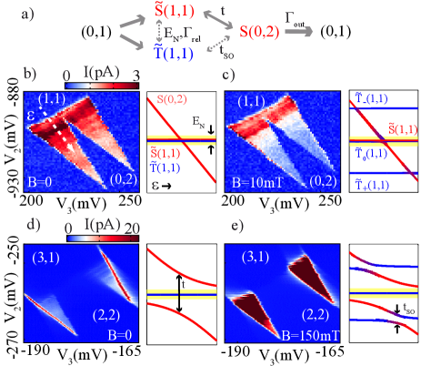
The spin states of the double dot are probed through spin blockade. A transition is spin-blocked when it is energetically allowed, but forbidden by spin conservation Ono et al. (2002). Current can flow through a double dot via a cycle of charge states. For example the cycle transfers one electron from left to right (Fig. 2(a)). The transition is forbidden when the (1,1) state is a triplet and the only accessible (0,2) state is a singlet. Therefore, spin blockade suppresses the current at this charge cycle. We observe spin blockade at several charge cycles that involve transitions for the first few electrons (Fig. 1, lower inset), as expected from simple spin filling Johnson et al. (2005b).
An incomplete spin blockade results in finite current through the double dot. This current is due to processes that enable transitions out of triplet (1,1) states (dashes in Fig. 2(a)). It was established in experiments on GaAs dots that hyperfine mixing results in transitions between different (1,1) states Koppens et al. (2005); Johnson et al. (2005a); Jouravlev and Nazarov (2006). Ref. Danon and Nazarov (2009) predicts that spin-orbit interaction can also lift spin blockade by hybridizing triplet (1,1) states with S(0,2). Bellow we describe how the contributions of the two interactions can be disentangled.
Flip-flops involving the fluctuating nuclear spin bath mix the (1,1) electron spin states only if they are close in energy. The characteristic energy scale over which the hyperfine interaction is effective is Merkulov et al. (2002), where A is the hyperfine constant, is the number of nuclei in the dot and is the average nuclear spin. The corresponding r.m.s. of nuclear field fluctuations is given by . (We measure the Landé g-factor by excited state spectroscopy.)
Due to spin-orbit interaction the (1,1) eigenstates become superpositions of spin triplets and the (1,1) singlet. We denote these (1,1) eigenstates with T̃-, T̃0, T̃+ and S̃. The spin singlet admixture in T̃ states is of the same order as the ratio of the dot size to the spin-orbit length . Because they contain a singlet component, T̃ states are coupled to S(0,2), which remains a spin singlet since both electrons in it belong to the same orbital. The exact coupling between T̃(1,1) and S(0,2) depends on the microscopic properties of the spin-orbit interaction in InAs nanowires and on the details of confinement Golovach et al. (2008). Here we simply parametrize this coupling with , where is the tunnel coupling between S(1,1) and S(0,2).
The energy levels calculated for weakly and strongly coupled double dots are shown in Figs. 2(b)-(e) as a function of the energy detuning between the (1,1) and (0,2) states. The calculation of the levels includes while disregarding the effect of nuclear spins. The effect of is represented by a yellow stripe: the (1,1) states within the stripe are mixed by the nuclei.
The principal roles of spin-orbit and hyperfine interactions can be illustrated by tuning the interdot tunnel coupling (Fig. 2). For small ,, the hyperfine-induced spin mixing dominates. The energy levels appear the same as for real spin singlets and triplets (Fig. 2(b),(c)) Hanson et al. (2007). In this limit the current is high at zero magnetic field, but is suppressed by a small magnetic field. This occurs for fields when the hyperfine mixing of the split-off states T̃+ and T̃- with the decaying (1,1) state is reduced.
The energy levels become noticeably modified when is large (Fig. 2(d),(e)). But the effect of this modification can only be seen at finite magnetic field. At zero field only one of the four (1,1) states is coupled to S(0,2) by the strength (Fig. 2(d)). The hyperfine mechanism cannot facilitate the escape from the uncoupled states because of the large singlet anticrossing, so the current is suppressed Koppens et al. (2005). At finite field, however, the eigenstates T̃+ and T̃- are coupled to the singlet S(0,2) by a large and the current increases (Fig. 2(e)). The current at finite field is limited by the escape rate from the remaining one blocked state.
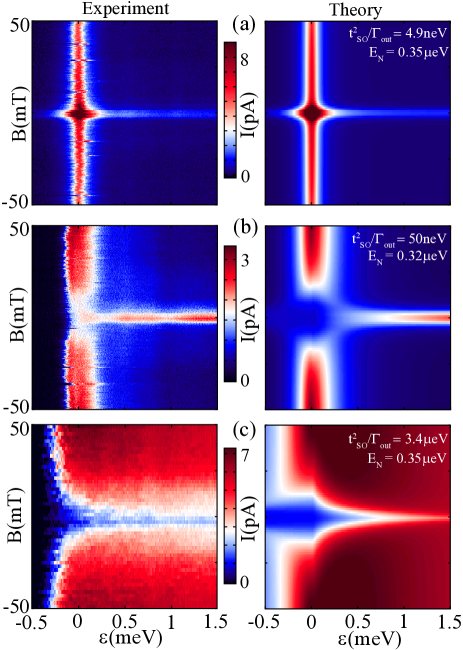
In a nutshell, hyperfine interaction lifts spin blockade for weak coupling and small fields, spin-orbit interaction - for strong coupling and large fields. The current may exhibit either a hyperfine-induced peak at zero magnetic field, or a dip due to spin-orbit interaction. The interplay of the two contributions gives rise to three distinct regimes as shown in Fig. 3. In the first regime, for weakest coupling, a zero field peak is observed for any detuning (Fig. 3(a)). In the intermediate regime, a dip around zero detuning becomes a peak at higher detuning. For the strongest coupling, the current only shows a dip at zero field (Fig. 3(c)). In all regimes the high-detuning behavior extends up to meV, where the (1,1) states are aligned with T̃(0,2) and spin blockade is lifted. The three regimes were observed at several spin-blockaded transport cycles, here we show the data from two of them (circles in Fig. 1).
The data are in good agreement with our simple transport theory that accounts for spin-orbit and hyperfine interaction Danon and Nazarov (2009). The three regimes are distinguished by the rate , where is the rate of escape from the S(0,2) into the outgoing lead (in eV). Intuitively, is the T̃(1,1) escape rate due to . When hyperfine mixing is the most effective process in lifting the spin blockade, see Fig. 2(a). This is the case in Fig. 3(a), where we observe a zero-field peak in the current. As is increased, we observe intermediate regime (Fig. 3(b)). Still, zero field peak persists at large detuning since becomes suppressed due to a reduced overlap of the (1,1) states with S(0,2). Around zero detuning, however, the hyperfine mixing at small fields is weaker than the spin-orbit coupling at finite fields, leading to a zero-field dip. In the third regime, for even higher , the zero-field dip is extended to high positive detuning (Fig. 3(c)). It should be stressed that the effects of both hyperfine and spin-orbit interactions are observed in all three regimes: current at higher fields is always enabled by spin-orbit interaction, and around zero magnetic field current is in part due to hyperfine mixing even for .
The peaks, dips and their widths, as well as the current levels are reproduced by a numerical simulation of transport through the spin-orbit eigenstates. The double dot current is obtained from stationary solutions of master equations Danon and Nazarov (2009). Spin mixing due to hyperfine interaction is included by averaging over thousends random nuclear fields. Current at high positive detuning is modeled by the inelastic transition rate, from S(1,1) and from the T̃(1,1) states. The function reflects the phonon density of states in the nanowire. We determine this function by matching the inelastic current in each regime. All three regimes are reproduced with and eV. The spin-orbit length nm can be estimated using nm ( in InAs). The values for are in agreement with the nuclei estimated from the dot size and eV. The values for and are as expected for InAs nanowires quantum dots Fasth et al. (2007); Pfund et al. (2007a).
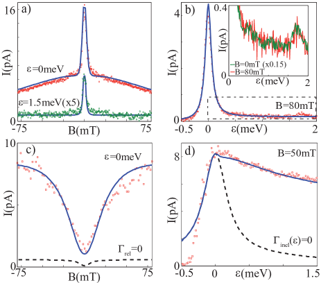
We now turn to a more quantitative analysis. The model is especially successful in reproducing the data in Fig. 3(a), where . In Figures 4(a) and 4(b) the linecuts along magnetic field and detuning are fitted using the same set of model parameters. The model allows to trace the influences of spin-orbit and hyperfine interactions through various features of the data. The narrow peak at zero field is mainly due to hyperfine mixing (Fig. 4(a)), similar to that observed in GaAs dots Koppens et al. (2005); Johnson et al. (2005a); Jouravlev and Nazarov (2006). However, the wider Lorentzian background at zero detuning is due to the strong spin-orbit coupling in InAs nanowires. The elastic current drops for mT, where the detuning between T̃±(1,1) exceeds the level broadening of S(0,2) set by .
The current is suppressed in the inelastic regime, that is for detuning (Fig. 4(b)). The remaining current, however, conveys information about the strength of spin-orbit interaction. At zero magnetic field the current is limited by the singlet tunneling , which is weak in this regime. At higher field the slowest process is the tunneling from T̃± states with a rate limited by , which is even weaker. The model Danon and Nazarov (2009) predicts a simple relation . The inset to Fig. 4(b) shows that the current at zero field scales to the current at finite field. From the ratio we determine for this regime.
The model helps identify another spin relaxation mechanism present in some of the data, such as shown in Fig. 3(c) and Fig. 4(c). A zero-field dip in the elastic current is reproduced by including the hyperfine mixing and the spin-orbit hybridization. However, the predicted current is much lower than in the experiment (dashed line in Fig. 4(c)). This discrepancy can be reconciled by introducing a field-independent rate of spin relaxation MHz which mixes all (1,1) states Danon and Nazarov (2009). This spin relaxation may be induced by electron-nuclear flip-flops mediated by phonons Erlingsson and Nazarov (2002), spin-spin interactions mediated by charge fluctuations and spin-orbit interaction Trif et al. (2008); Flindt et al. (2006) or by virtual processes such as cotunneling or spin exchange with the leads. The magnitude of depends on the gate settings, and is not directly related to the magnitudes of or .
In this regime we also observe large inelastic current (Fig. 3(c)), which implies a high inelastic rate . Figure 4(d) shows the contribution of inelastic current compared to the expected elastic current. Some peculiarities of the data in Figs. 3(b), (c) are not captured by the model. The current onset is unexpectedly sharp as the detuning is increased (Figs. 3(b), (c), 4(d)). A possible reason for this discrepancy could be dynamic nuclear polarization not included in our model. It is known that dynamic nuclear polarizations can cause sharp current switches Ono and Tarucha (2004). Another explanation is that a sharp inelastic resonance at small detuning enhances the current Weber et al. (2010).
In conclusion, we separate the effects of spin-orbit and hyperfine interactions in the spin-blockade regime of a double quantum dot. These findings will guide the development of spin-orbit controlled qubits. Further insights into spin-orbit interaction in nanowires can be obtained from direct measurements of spin coherence times.
We thank K.C. Nowack, L.M.K. Vandersypen and M.C. van der Krogt for their help. This work has been supported by NWO/FOM (Netherlands Organization for Scientific Research) and through the DARPA program QUEST.
References
- Loss and DiVincenzo (1998) D. Loss and D. P. DiVincenzo, Phys. Rev. A 57, 2070 (1998).
- Hanson et al. (2007) R. Hanson et al., Rev. Mod. Phys. 79, 1217 (2007).
- Nowack et al. (2007) K. C. Nowack et al., Science 318, 1430 (2007).
- Foletti et al. (2009) S. Foletti et al., Nature Physics 5, 903 (2009).
- Koppens et al. (2005) F. H. L. Koppens et al., Science 309, 1246 (2005).
- Johnson et al. (2005a) A. C. Johnson et al., Nature 435, 925 (2005a).
- Pfund et al. (2007a) A. Pfund et al., Phys. Rev. Lett. 99, 036801 (2007a).
- Pfund et al. (2007b) A. Pfund et al., Phys. Rev. B 76, 161308(R) (2007b).
- Churchill et al. (2009) H. O. H. Churchill et al., Nature Physics 5, 321 (2009).
- Petta et al. (2005) J. R. Petta et al., Science 309, 2180 (2005).
- Koppens et al. (2006) F. H. L. Koppens et al., Nature 442, 776 (2006).
- Jouravlev and Nazarov (2006) O. N. Jouravlev and Y. V. Nazarov, Phys. Rev. Lett. 96, 176804 (2006).
- Danon and Nazarov (2009) J. Danon and Y. V. Nazarov, Phys. Rev. B 80, 041301(R) (2009).
- Fasth et al. (2007) C. A. Fasth et al., Phys. Rev. Lett. 98, 266801 (2007).
- Buizert et al. (2008) C. Buizert et al., Phys. Rev. Lett. 101, 226603 (2008).
- van Tilburg et al. (in preparation) J. W. W. van Tilburg et al. (in preparation).
- Ono et al. (2002) K. Ono et al., Science 297, 1313 (2002).
- Johnson et al. (2005b) A. C. Johnson et al., Phys. Rev. B 72, 165308 (2005b).
- Merkulov et al. (2002) I. A. Merkulov et al., Phys. Rev. B 65, 205309 (2002).
- Golovach et al. (2008) V. N. Golovach et al., Phys. Rev. B 77, 045328 (2008).
- Erlingsson and Nazarov (2002) S. I. Erlingsson and Y. V. Nazarov, Phys. Rev. B 66, 155327 (2002).
- Trif et al. (2008) M. Trif et al., Phys. Rev. B 77, 045434 (2008).
- Flindt et al. (2006) C. Flindt et al., Phys. Rev. Lett 97, 240501 (2006).
- Ono and Tarucha (2004) K. Ono and S. Tarucha, Phys. Rev. Lett. 92, 256803 (2004).
- Weber et al. (2010) C. Weber et al., Phys. Rev. Lett. 104, 036801 (2010).