Correlated time-dependent transport through a 2D quantum structure
Abstract
We use a generalized master equation (GME) to describe the nonequilibrium magnetotransport of interacting electrons through a broad finite quantum wire with an embedded ring structure. The finite quantum wire is weakly coupled to two broad leads acting as reservoirs of electrons. The mutual Coulomb interaction of the electrons is described using a configuration interaction method for the many-electron states of the central system. We report some non-trivial interaction effects both at the level of time-dependent filling of states and on the time-dependent transport. We find that the Coulomb interaction in this non-trivial geometry can enhance the correlation of electronic states in the system and facilitate it’s charging in certain circumstances in the weak coupling limit appropriate for the GME. In addition, we find oscillations in the current in the leads due to the correlations oscillations caused by the switched-on lead- system coupling. The oscillations are influenced and can be enhanced by the external magnetic field and the Coulomb interaction.
pacs:
73.23.Hk, 85.35.Ds, 85.35.Be, 73.21.LaI Introduction
The Coulomb blocking of electrons entering nanostructures has been known for quite some time and is explained by the magnitude of the direct part of the repulsive Coulomb interaction energy in relation to the energy spectrum of the nanosystem.Kouwenhouven (1997) The experimental and theoretical studies of Coulomb effects on the mesoscopic transport were commonly focused on steady-state regime of single or double quantum dots. However, the increasing interest in fast dynamics at nanoscale and time-resolved detection of electrons via a nearby detector strongly motivates theoretical investigations of interacting time-dependent transport in complex systems. The dynamical aspects of the Coulomb blocking have been investigated by Kurth et al. in a one-dimensional lattice model using combination of non-equilibrium Green’s functions and time dependent density-functional theory for the Coulomb interaction.Kurth et al. (2009)
In a recent work Moldoveanu et al. (2010) we have also analyzed the transient currents through an interacting two-dimensional quantum dot by solving the generalized master equation for the matrix elements of the reduced density operator acting in the Fock space of interacting many-electrons states of the dot. The GME scheme that we implement numerically takes into account the geometrical details of the sample and leads (see Ref. Moldoveanu et al., 2009). Our aim here is to apply the same method to more complex systems in order to single out non-trivial Coulomb effects in the transient regime. The system we consider is a parabolic quantum wire with an additional ring-shaped confining potential. The embedded ring geometry imposes different localization properties of the states with respect to the regions where the leads are attached. This fact has important consequences on the time-dependent filling of the many-electron states.
Even though the transport and magnetic properties of quantum rings have fascinated researchers for a long time new questions and results regarding the Aharonov-Bohm interference oscillations have been catching attention.Camino et al. (2005, 2007); Ihnatsenka and Zozoulenko (2008) Dynamical effects have been studied in open or closed quantum rings. Propagation of electron pulses in rings of finite width has been investigated by Chaves et al.Chaves et al. (2009) and by Thorgillsson et al. Thorgilsson et al. (2007) within scattering theory, and non-adiabatic current generation in a closed finite quantum ring in an external magnetic field has been studied by integrating the Liouville-von Neumann equation for the density operator in time.Gudmundsson et al. (2003) The system was perturbed by a strong dipole or higher order multipolar electric electric field pulse and the mutual Coulomb interaction between the electrons was included in a mean-field DFT manner.
We use a non-Markovian version of the generalized master equationMoldoveanu et al. (2009); Gudmundsson et al. (2009) and treat the Coulomb interaction of the electrons exactly within a truncated many-electron basis.Moldoveanu et al. (2010) The GME formalism was originally proposed by Nakajima and Zwanzig,Nakajima (1958); Zwanzig (1960) and has more recently been applied to study transport phenomena by several authors, Timm (2008); Harbola et al. (2006); Welack et al. (2008); Vaz and Kyriakidis (2008) just to cite few.
The paper is organized as follows: Section II sets the notations and presents briefly the formalism, Section III describes the quantum wire structure with the embedded ring, Section IV contains the results and their discussion while Section V is left for conclusions.
II The GME and the Coulomb interaction
In this Section we recall the main outlines of the GME method leading to the numerical results. The time-dependent transport of noninteracting electrons with the generalized master equation has been described in two publication for a lattice modelMoldoveanu et al. (2009) and a continuous model.Gudmundsson et al. (2009) The non-interacting many-electron Hamiltonian of the coupled system (i.e. the central sample, the leads and time-dependent coupling) reads as
| (1) |
where the tunneling Hamiltonian describes the coupling of the system to the left and right leads
| (2) |
The creation and annihilation operators are associated to single particle states of the disconnected subsystems. The coupling coefficient of a single-electron state in the lead to a state in the system is modelled as a non-local overlap integral of the corresponding wave functions in the contact regions of the system, , and the lead , Gudmundsson et al. (2009)
| (3) |
The function
| (4) |
with and defines the ‘nonlocal overlap’ and their affinity in energy. The semi-infinite leads have the same parabolic confinement as the finite quantum wire in the -direction, perpendicular to the transport direction . The confinement is characterized by the energy scale , The energy spectrum of the leads is continuous, but with clear subband structure. The effects of the external magnetic field is present in the energy spectrum of the leads , the spectrum of the system , and in the wave functions of the leads and the system.
In order to describe the time-dependent transport when the system contains few electrons we select the lowest single electron states (SES) of the central system to construct a Fock space with many-electron states (MES). In the occupation representation basis such a state can be written as
| (5) |
where is the occupation of the single particle state of the isolated system. is selected large enough that the chemical potentials of the leads in equilibrium before the coupling at are smaller than the energy of the highest SES, and ideally a further increase of should not change the transport results of the calculations.
The Liouville-von Neumann equation describing the time-evolution of the total system, central system and leads
| (6) |
where the equilibrium density operator of the disconnected lead with chemical potential is
| (7) |
is now projected on the central system by partial tracing operations with respect to the operators of the leads. Defining the reduced density operator (RDO) of the central system
| (8) |
we obtain an integro-differential equation for the RDO, the generalized master equation (GME)
| (9) | |||||
where two operators have been introduced to compactify the notation
with , and a scattering or coupling operator acting in the Fock space of the system
| (10) | |||||
| (11) |
Here the kernel of the integro-differential equation has been obtained by taking into account only second order processes with respect to the coupling coefficients. It should though be kept in mind that the structure of the equation implies higher order processes to infinite order.
In the derivation of the GME here only the coupling Hamiltonian is allowed to depend on time. The possibility of the Hamiltonian of the central system depending on time (describing a laser pulse for example) has been considered by Amin et al.Amin et al. (2009) A DFT description of the mutual Coulomb interaction of the electrons in the central system would require to be time-dependent, and it would also require a further reduction of the GME introducing the reduced single-particle density matrix loosing some many-electron correlation effects caused by the coupling of the system to the leads.Li and Yan (2007)
Our approach to solve this dilemma has been reported earlier,Moldoveanu et al. (2010) but here we shall briefly outline it for the case of the continuous model. We choose to change the Hamiltonian of the central system
| (12) |
to include the time-independent Coulomb interaction term appropriate for our many-electron formalism. The Coulomb potential is
| (13) |
and the matrix elements are
| (14) |
with
| (15) |
and is a small convergence parameter to be specified later. Along the lines of approaches developed under the names of “configuration interaction” or “exact numerical diagonalization” we diagonalize the new interacting Hamiltonian (12) in the MES basis of the non-interacting system in the entire Fock space built from the SES states, including all sectors containing zero electrons (the vacuum state) to electrons, since we are dealing with an open system with variable number of electrons. The diagonalization yields a new basis of interacting MES connected to the non-interacting one by a unitary transformation
| (16) |
supplied by the diagonalization. Here we need to keep in mind that will be represented by an matrix in numerical calculations. An inspection of the structure of the non-interacting GME (9) reveals that the equation can be also be transformed to the interacting basis by the unitary transformation. Thus, in a numerical calculation a basis transformation of the many-electron coupling matrix (11) and the insertion of the diagonalized matrix representation of the interacting in the GME (9) will give the RDO in the interacting MES basis . As all measurable quantities are in the end expressed as a partial trace with respect to operators of the central system expectation values can be calculated in the new basis and for the same reason in the non-interacting case we can again obtain the mean value of the left or right current directly from the transformed GME.
In our earlier publicationGudmundsson et al. (2009) neglecting the Coulomb interaction it was clear that we could only effectively describe the time-dependent transport through systems with up to 7 or 8 SES considered relevant for the currents, situated in and around the window of the chemical potentials of the two leads. This limitation was imposed by the complex bandstructure of the energy spectrum in the broad leads employed in the calculations. Here, we may have to include more SESs in order to describe reasonably the interaction of the electrons in the central system. In order to accomplish this we have to resort to a more refined truncation procedure than we used for the non-interacting system: The unitary transformation can not be truncated and has to include the states constructed initially from the SESs. In the numerical calculations here we will employ 12 SES leading to 4096 MES. The unitary transformation of is thus CPU-time intensive for all the -values necessary for the leads, but it has only to be performed once. After that it is possible to deploy a second truncation to the GME by keeping only the MES with lowest energy. Typically, for the parameters that we will select for the numerical calculations here we need only , but this cutoff is very system dependent.
III Embedded quantum structure
Here we will use the GME to analyze time-dependent transport of electrons through a short but broad quantum wire of length nm, with an embedded quantum ring. The parabolic confinement of the quantum wire is characterized by the energy scale meV, and we assume GaAs parameters with and . The embedded ring is represented by the potential
| (17) |
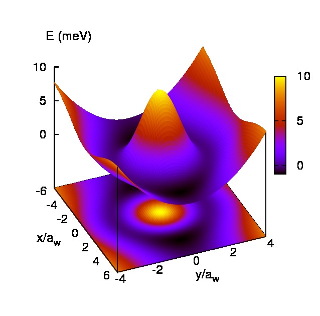
with meV, meV, nm-1, nm-1, nm-1, and nm-1. The parameter can be thought of as a gate voltage. We use it to position the chemical potential of the right lead at a similar place in the energy spectrum of the SESs for the two values of the magnetic field investigated here. (For T we use meV and for T we have meV). Figure (1) shows the ring embedded in the quantum wire with the spatial coordinates scaled by the magnetic length modified by the parabolic confinement , with at T, where the cyclotron frequency is . At T nm.
In the following calculations we use for the coupling (4) nm-2, meV, and meV or 40 meV.
The energy spectra for the closed system of a quantum wire with an embedded ring are shown for the SESs and the MESs in Figure 2 with the chemical potential of the right lead to be used in the following dynamical calculations indicated.
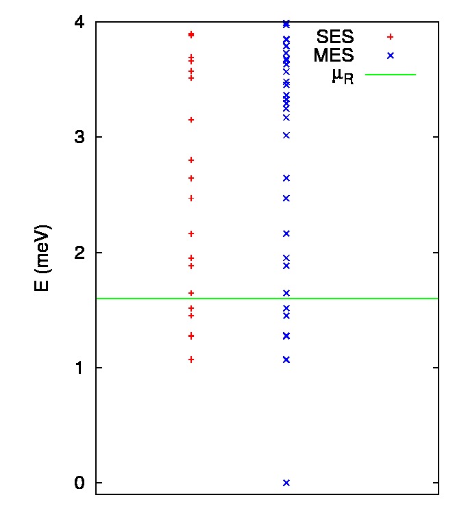
As will be evident from the probabilities of the SESs the two lowest SES states are almost degenerate, so below there are 6 SESs. In the dynamical calculation to follow we will use the 12 lowest SESs to build the relevant MESs. Besides the vacuum MES at zero energy we thus recognize the 12 SESs again as MESs occupied by only one electron each. Above the energy of the highest SES accounted for we have a relatively dense spectrum of MESs occupied by 2 electrons. Due to the strong Coulomb interaction the lowest MES occupied by 3 electrons is located well above the highest energy shown in Fig. 2.
The value of meV is selected such that below it there are both SESs localized away from the contact region and states with a strong weight in that region. The probability for the SESs is displayed in Figure 3.


IV Dynamical transport properties
In a recent paper Moldoveanu et al. (2010) among other things we demonstrated a dynamical Coulomb blocking effect in a small system where all the relevant SESs are extended. There, the mutual Coulomb interaction between the electrons in the system prevents the entrance of further electrons until the bias is high enough and the occupation of the system in the steady state regime shows the well known Coulomb steps as a function of the bias between the left and right leads. The time-dependence of the contact functions is described by
| (18) |
with ps-1. We fix the temperature of the reservoirs at K.
IV.1 Enhanced occupation by the Coulomb interaction
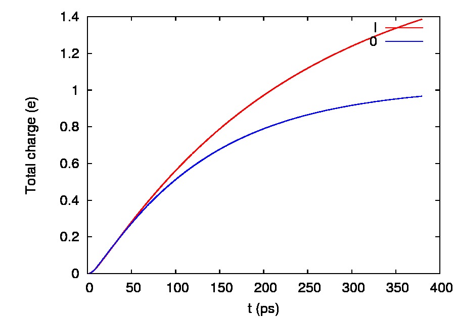
Here, in a system where not all the states of the system are extended we will show that the Coulomb interaction can bring about a totally different dynamical effect: Fig. 4 shows that even for a small bias meV only one electron seems to be able to enter the initially empty system in the absence of the Coulomb interaction, but the Coulomb interaction seems to facilitate the entrance of the second electron into the system.
A glance at Figures 5 and 6 showing the occupation of the MESs in case of the interacting and the non-interacting system, respectively, indicates a very different charging effect for the two cases.
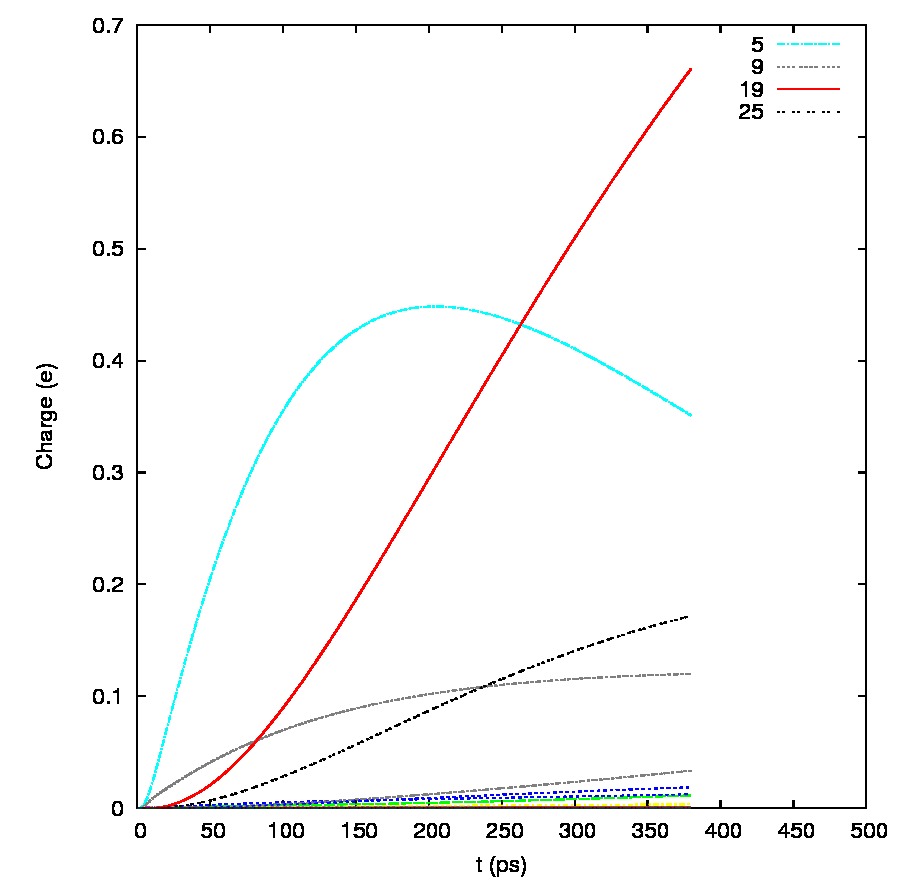
In the case of the non-interacting system the one-electron MES is occupied up to 78% after ps and the state carries 12% with the rest distributed to several states. For the interacting system the one-electron state is again initially occupied with a slight occupation of , but soon they loose to the two-electron MES and that take over. The state is a two-electron state with the main contributions from , , , , and . is also a two-electron MES with the main contributions from , , , , and .
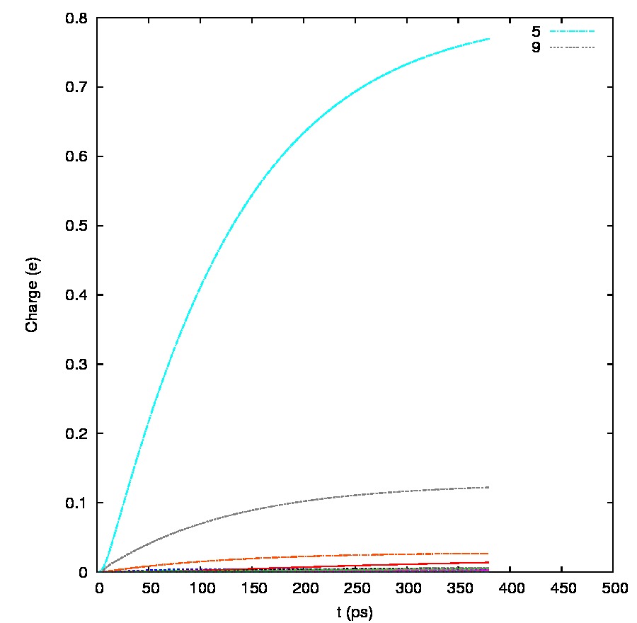
The energy of the state is meV and the mean energy for the same range of time seen in Fig. 7 is higher for the interacting case.
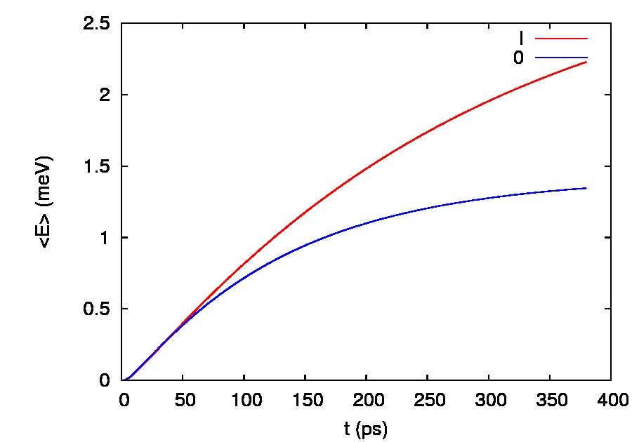
We assume the leads are in equilibrium before the coupling to the wire at at a temperature of K corresponding to 0.043 meV. The energy meV of is valid for the case of exactly two electrons in the state, here we can only explain the occupation of this state well above with the fact that it is only partially occupied. In other words the SES elements which build the MES are only partially occupied. This corresponds well with the values of the mean energy in Fig. 7.
In the non-interacting case one electron can enter the system and it occupies the state just below . This state is the lowest state with high weight in the contact region, below which only states (, ) exist with more weight away from the region of contacts, in the sides of the quantum ring, as Fig. 3 confirms. (The state , or , is nearly degenerate with but does not participate in the transport to large extent for the non-interacting case). The Coulomb interaction couples together these two different types of states and facilities thus the occupation of two-electron states with one of the electrons in a low energy SES state with poor coupling to the contacts. Similar phenomena is observed at T if the chemical potential in the right lead is placed in a corresponding location with respect to the 12 non-interacting SESs used in the calculation by varying .
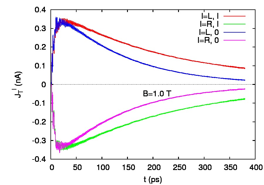
The current in the left and right leads displayed in Fig. 8 shows that neither the interacting nor the non-interacting systems have reached a steady state in the 380 ps shown. Both leads are still supplying charge to the system, but in the case of the interacting system the time constants are clearly longer for the charging process that is enhanced by the Coulomb interaction.
The many-electron charge distributions compared in Fig. 9 for the non-interacting and the interacting system at ps confirm this observation and reminds us that the two-electron state in the right panel has a relatively low interaction energy due to the reduced overlap of states with high probability in the contact region and states with high probability at the other sides of the ring.


In Fig. 10 we compare the truncated RDO for the case of the non-interacting and the interacting system at ps. On the diagonal in the left panel we see again as in Fig. 6 that for the non-interacting case only state has considerable occupation, while the vacuum state is loosing its initial high value and state is gaining some weight. So, only one-electron states are occupied here. In the case for the interacting system the right panel of Fig. 10 shows as Fig. 5 a strong emergent occupation of , a two electron state. Figure 2 revealed a small energy gap between the single-electron states and the many-electron states of the interacting system. The GME-formalism excludes any correlation between MESs with a different number of electrons. A manifestation of this can be seen in the right panel of Fig. 10 where only vanishing off-diagonal elements can be found in the upper left and the lower right rectangles correlating one- and two-electron states. (The one-electron states being ). For the non-interacting case in the left panel of Fig. 10 this separation is not as clear cut since there the regions of one- and two electrons states overlap slightly. More importantly, Fig. 10 reveals a non-vanishing correlation between all two-electron states that gain any occupation in the system.


Initially for both cases only the vacuum state was occupied, so clearly the coupling to the leads brings about correlation of the electrons in the system, and in addition, the Coulomb interaction strongly influences this correlation.
IV.2 Current oscillations
In this subsection we will compare the total current in the leads for two different values of the magnetic field, i.e. at T and T, and observe how the current changes as the bias is increased. We find that the current exhibits smooth oscillations with a period of several picoseconds for the higher magnetic field as the bias is increased. Here we should mention right away that we are not describing the small oscillations seen in Fig. 8 at a shorter time scale, that are caused by an interference of the coupling to different subbands of the leads. (In the case of a one-dimensional lead like has been used in the lattice version of the GME-model these oscillations do not appear).Moldoveanu et al. (2009)
The lowest 32 levels of the many-electron energy spectra for the two different values of the magnetic field are displayed in Fig. 11,
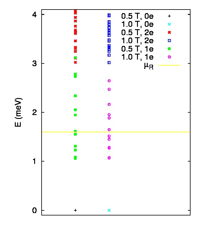
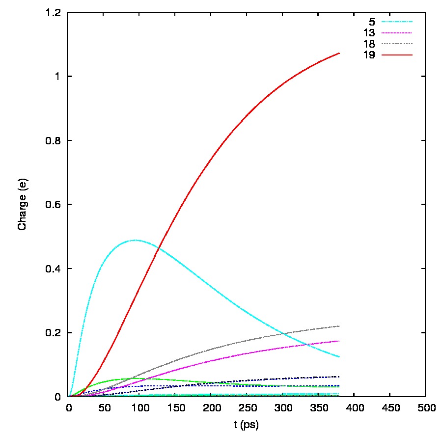
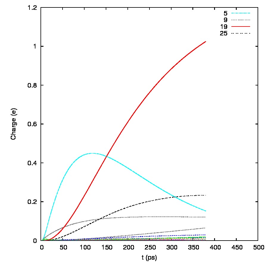
where a care has been taken to identify the one- and two-electron MESs for both cases with different symbols. Here, meV. We note that for T the one- and two-electron MESs are separated by a small energy gap, but not for T. The time-dependent occupation probability of the MESs is demonstrated in Fig. 12.
Further analysis of the state structure of the system is done in Table 1 for T, and in Table 2 for T.
| 1e | meV | ||
| 100.0% | |||
| 1e | meV | ||
| 100.0% | |||
| 2e | meV | ||
| 11.8% | |||
| 9.1% | |||
| 11.3% | |||
| 20.1% | |||
| 35.5% | |||
| 2e | meV | ||
| 20.2% | |||
| 4.9% | |||
| 29.0% | |||
| 12.3% | |||
| 17.8% |
At T mainly the one-electron state is initially occupied with lesser probability for . Without the Coulomb interaction only these two states with the same components will gain any significant probability of occupation. Similarly, as in previous section where we analyzed the occupation of the system at a lower bias we see here that the Coulomb interaction facilitates the coupling to the lower lying states and thus increases the probability of the occupation of a two-electron state with one of the electrons in a low energy SES. The next two-electron state to gain significant occupation probability is with a bit higher energy and a higher likelihood for one of the electrons to be just above .
Very similar picture is seen in Table 2 for the state-structure at T, with the exception that only a single one-electron state gains significant occupation probability and the two-electron states coming in after the most probable one, , are lower in energy than that one. Also, though not shown here the non-interacting system at T will gain a slight probability for the occupation of a two-electron states. This is caused by the missing gap between the one- and two-electron states that we earlier pointed out in Fig. 11.
| 1e | meV | ||
| 100% | |||
| 2e | meV | ||
| 12.0% | |||
| 22.4% | |||
| 33.8% | |||
| 4.6% | |||
| 10.1% | |||
| 2e | meV | ||
| 88.2% | |||
| 4.5% | |||
| 6.4% | |||
| 2e | meV | ||
| 10.4% | |||
| 73.8% | |||
| 11.3% |
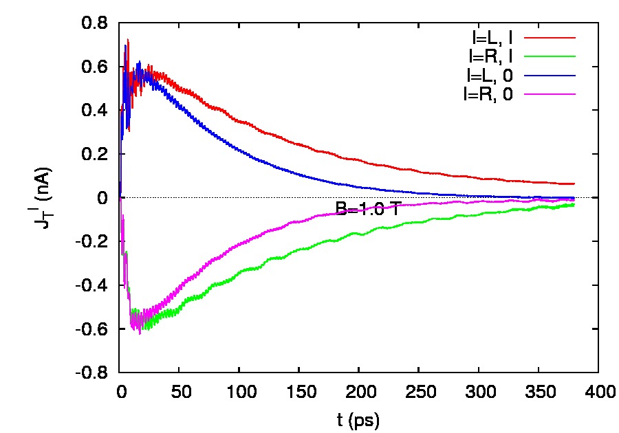
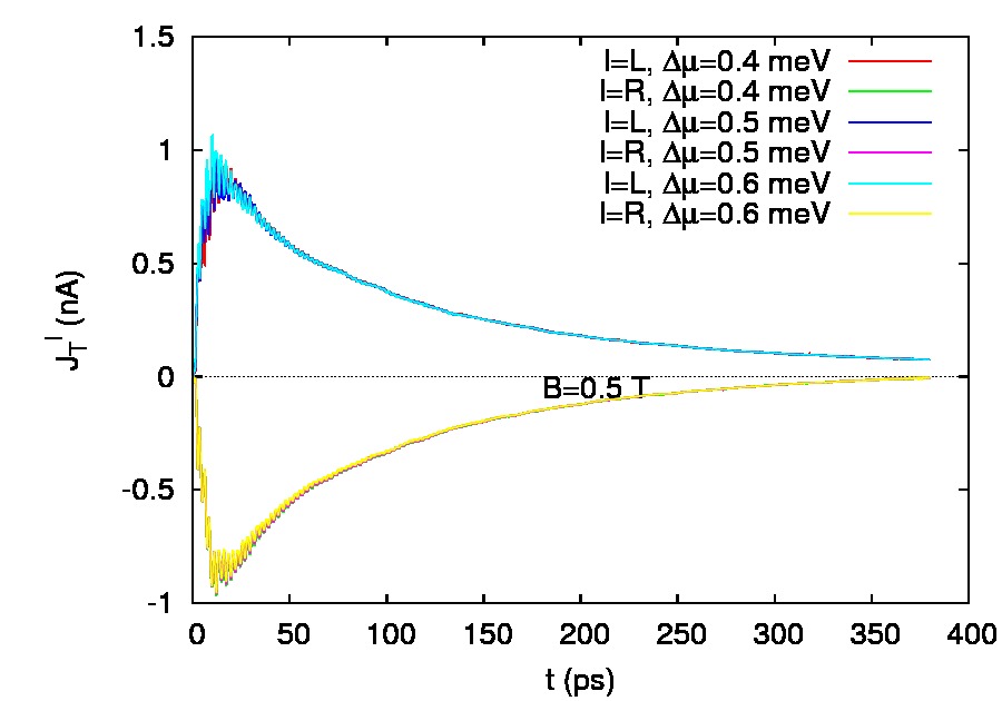
Figure 13 compared the total current in the left and right leads for T in the top panel for a non-interacting and an interacting system. Both show smooth oscillations after the initial transient period, but they are clearer for the interacting system.
.
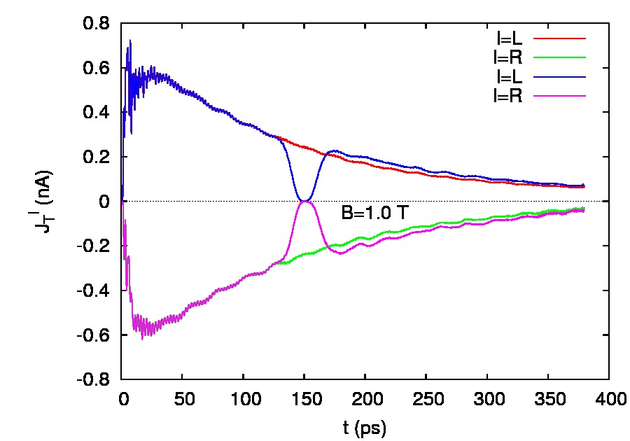
The center panel of Fig. 13 demonstrates that the oscillations in the current are not changed to any extent by smoothly decoupling the system momentarily from the leads around ps. The bottom panel of Fig. 13 indicates that for the case of T the oscillations are either absent or too weak to be discernible. Clearly, the system is not in its ground state, the coupling to the leads moves it out of equilibrium, and a glance at Tables 1 and 2 observing what kind of states are available to the system awakens the question if the coupling has generated collective oscillations as in the case of the closed ring subject to strong external perturbation.Gudmundsson et al. (2003) In the case of the system without an interaction the single electron states would have a restoring force from the potential defining the wire and the ring which do not have a totally flat bottom, see Fig. 1. But here the coupling to the leads is weak, the momentary switch-off of it does not influence the oscillations, and an inspection of the density confirms that the density only shows minute oscillations that we will describe below.
The dynamic evolution is governed by the GME (9) and in Fig. 14 we display the correlation of the two-electron state that gains the highest occupation probability with time in our system, i.e. the off-diagonal elements of the RDO, .


For both values of the magnetic field we see indeed oscillations with comparable period as the smooth oscillations in the current, but in the case of the lower magnetic field many elements show strong oscillations but not in phase. For the higher magnetic field only one or two elements oscillate and one of them is clearly stronger.
We see thus that oscillations of the electron correlations are inherent in the GME formalism irrespective of the presence of the Coulomb interaction or not. It is a part of the correlations forced on various states of the system by the coupling to the leads. Here, we observe that the Coulomb interaction further couples different types of states in the system. States with weak coupling to the leads residing in regions of the system away from the contact area with states with higher presence in the contact area. Furthermore, the magnetic field simplifies the energy spectrum of the system such that oscillations in the correlation of a single pair of MESs will be dominant and thus visible in the total current.
As was stated before the oscillations in the density caused by the oscillation in the electron correlation are minute. We thus display in Fig. 15 the “derivative” density or induced density defined by , where we have taken ps instead of comparing always to the density at a certain fixed point in time, the reason being that the electron charge is still increasing in the time interval used and we see the density peaks in the ring away from the contact area always growing.

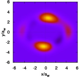
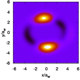
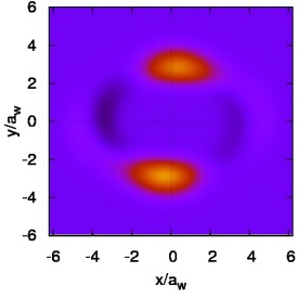
In addition, we see that electron density or charge is shifted between the peaks and the contact area thus influencing the effective coupling between the system and the leads.
In order to check the stability of the results with respect to the exact location of the window of chemical potential we have repeated the calculations for meV. The results are very similar with respect to the oscillations observed in the current and the occupation of the MESs. The states gaining highest occupation are still the same but at meV additional MESs with a bit higher energy show up with low occupation that were almost empty for meV. At present we do not feel confident to increase the height of the bias window further due to the fact that we have only included 12 SESs in the calculation.
V Summary
We have used a time-dependent transport formalism built on the generalized master equation (GME) where the mutual Coulomb interaction between electrons is treated within the “exact numerical diagonalization” or “configuration interaction” to analyze the transport properties of a quantum two-dimensional ring or a short 2D quantum wire with an embedded ring. The quantum wire is defined by a parabolic confinement potential in the wire plane perpendicular to the transport direction. The ends of the quantum wire are hard walls that are made transparent to tunneling by a weak coupling to leads. The shape of the finite wire and the definition of the ring potential (17) leads to a ring system with a potential that does not have a totally flat bottom, see Fig. 1. For this reason we have a system that has SESs that are ring states for higher energy, but the lowest states can be slightly localized in different part of the system. We show that indeed, in this geometry the Coulomb interaction between the electrons increases the occupation of the system by coupling states with different localization properties. The correlation of the states in the system caused by the coupling to the leads is enhanced by the Coulomb interaction leading to a behavior that runs counter to the usual Coulomb blockade in a simpler geometry. Of course the Coulomb blocking mechanism is inherent in the interacting system, but by comparing the interacting system with the noninteracting one we discover finer details in the action of the interaction, details that are usually collected under the title: correlation effects.
In addition we find current oscillations that are caused by oscillating correlation properties of the electrons in the system. These oscillations become visible in higher magnetic field due to the reduction of MESs active in the transport by the magnetic field. As the correlations are caused by the coupling to the leads the oscillations are visible in systems without or with Coulomb interaction between the electrons, but the Coulomb interaction influences them through its enhancing of correlations by coupling of electronic states.
Acknowledgements.
The authors acknowledge financial support from the Research and Instruments Funds of the Icelandic State, the Research Fund of the University of Iceland, the Icelandic Science and Technology Research Programme for Postgenomic Biomedicine, Nanoscience and Nanotechnology, the National Science Council of Taiwan under contract No. NSC97-2112-M-239-003-MY3, and the Reykjavik University Development Fund T09001. V. M. acknowledges the hospitality of the Reykjavik University, Science Institute and the partial support from PNCDI2 program (grant No. 515/2009 and Grant No. 45N/2009).References
- Kouwenhouven (1997) L. Kouwenhouven, in NATO Advanced Study Institute, edited by L. Sohn, L. Kouwenhouven, and G. Schön (Kluwer, Dordrecht, 1997), vol. 345 of Series E.
- Kurth et al. (2009) S. Kurth, G. Stefanucci, E. Khosravi, C. Verdozzi, and E. Gross (2009), arXiv:0911.3870, URL http://arxiv.org/abs/0911.3870.
- Moldoveanu et al. (2010) V. Moldoveanu, A. Manolescu, C.-S. Tang, and V. Gudmundsson, arXiv:1001.0047 (2010).
- Moldoveanu et al. (2009) V. Moldoveanu, A. Manolescu, and V. Gudmundsson, New Journal of Physics 11, 073019 (2009), URL http://stacks.iop.org/1367-2630/11/073019.
- Camino et al. (2005) F. E. Camino, W. Zhou, and V. J. Goldman, Phys. Rev. B 72, 155313 (2005), URL http://link.aps.org/doi/10.1103/PhysRevB.72.155313.
- Camino et al. (2007) F. E. Camino, W. Zhou, and V. J. Goldman, Phys. Rev. B 76, 155305 (2007), URL http://link.aps.org/doi/10.1103/PhysRevB.76.155305.
- Ihnatsenka and Zozoulenko (2008) S. Ihnatsenka and I. V. Zozoulenko, Phys Rev. B 77, 235304 (2008).
- Chaves et al. (2009) A. Chaves, G. A. Farias, F. M. Peeters, and B. Szafran, Phys. Rev. B 80, 125331 (2009), URL http://link.aps.org/doi/10.1103/PhysRevB.80.125331.
- Thorgilsson et al. (2007) G. Thorgilsson, C.-S. Tang, and V. Gudmundsson, Phys. Rev. B 76, 195314 (2007).
- Gudmundsson et al. (2003) V. Gudmundsson, C.-S. Tang, and A. Manolescu, Phys. Rev. B 67, 161301(R) (2003).
- Gudmundsson et al. (2009) V. Gudmundsson, C. Gainar, C.-S. Tang, V. Moldoveanu, and A. Manolescu, New Journal of Physics 11, 113007 (2009), URL http://stacks.iop.org/1367-2630/11/113007.
- Nakajima (1958) S. Nakajima, Prog. Theor. Phys. 20, 948 (1958).
- Zwanzig (1960) R. Zwanzig, J. Chem. Phys. 33, 1338 (1960).
- Timm (2008) C. Timm, Phys. Rev. B 77, 195416 (2008).
- Harbola et al. (2006) U. Harbola, M. Esposito, and S. Mukamel, Phys. Rev. B 74, 235309 (2006), URL http://link.aps.org/abstract/PRB/v74/e235309.
- Welack et al. (2008) S. Welack, M. Esposito, U. Harbola, and S. Mukamel, Phys. Rev. B 77, 195315 (2008), URL http://link.aps.org/abstract/PRB/v77/e195315.
- Vaz and Kyriakidis (2008) E. Vaz and J. Kyriakidis, Journal of Physics Conference Series 107, 012012 (2008).
- Amin et al. (2009) A. F. Amin, G. Q. Li, A. H. Phillips, and U. Kleinekathöfer, Eur. Phys. J. B 68, 103 (2009).
- Li and Yan (2007) X.-Q. Li and Y. Yan, Phys. Rev. B 75, 075114 (2007).