Surface Plasmon Polariton microscope with Parabolic Reflectors
Abstract
We report the realization of a two–dimensional optical microscope for surface plasmons polaritons (SPPs) based on parabolic Bragg mirrors. These mirrors are built from lithographically fabricated gold nanostructures on gold thin films. We show by direct imaging by leakage radiation microscopy that the magnification power of the SPP microscope follows basic predictions of geometrical optics. Spatial resolution down to the value set by the diffraction limit is demonstrated.
Surface plasmon polaritons (SPPs) are propagative electromagnetic waves bound to the interface between a metal and a dielectric Raether . As such, SPPs offer several possibilities for two–dimensional optical functionalities at micro- and nanometer scales Barnes:2003 . Various quasi two–dimensional SPP elements were demonstrated recently such as waveguides Weeber-Lacroute-Dereux:2003 ; Nikolajsen:2003 ; Harry2005 , lenses Hohenau ; Liu , reflectors Harry ; Yin and interferometers Harry ; Drezet ; sergey . In particular, the realization of an elliptical interferometer for SPPs based on confocal Bragg reflectors built on a flat gold film was reported Drezet . In this interferometer SPPs launched from the first focal point are efficiently focussed in the second focal point after propagating inside an elliptical cavity. Clearly such a geometry can as well be used for in–plane microscopic imaging limitation . In fact, SPP microscopy has been a topic of increased interest recently, including some controversy about the achievable spatial resolution smolya ; comment . For geometrical reasons, however, an elliptical geometry does not allow to obtain an image magnification much different from unity. To overcome this limitation we report here the realization of an SPP in–plane microscope with parabolic mirrors. We realize two–dimensional SPP imaging with variable magnification and show that a spatial resolution of about half the SPP wavelength is attainable in agreement with the Abbe-Rayleigh criterion Teich ; Andrey2 .
All structures discussed in the following are built from gold nanoprotrusions (150 nm diameter, 70 nm height) fabricated by standard electron–beam lithography M3:1997 on a 70 nm thick gold thin film on glass substrate. To achieve SPP reflectivity close to unity a Bragg mirror geometry has been chosen for the reflectors constituted by 11 parabola sharing the same focal point (and having thus slightly different focal lengths) and the same symmetry axis. The individual parabola are built from closely spaced protrusions (center–to–center distance nm). Constructive interference occurs between the various reflected and refocussed SPP waves if the closest separation between two neighboring parabola (measured along the symmetry axis) equals , where is the SPP wavelength which is here fixed to 785 nm, corresponding to a laser excitation wavelength of 800 nm.
As a first example we consider a confocal geometry composed of two parabolic reflectors having the same focal length and common symmetry axis (see Fig. 1). The object to be imaged is located close to . From the geometrical properties of parabola mirrors one can see that the light path (where is the effective SPP reflection point on the parabola and is the horizontal projection of onto a line perpendicular to the parabola axis, see Fig. 1A) is independent of the choice of the position of . Clearly this means that is projected into a SPP beam propagating along and finally that a SPP launched in is refocussed in .
In Fig. 1B the object in is a single gold nanoprotrusion. SPPs are launched on the metal film by focussing on this nanoprotrusion a laser beam impinging perpendicularly to the surface with a polarization direction oriented along the vertical direction. The imaging of SPP propagation is accomplished by leakage radiation microscopy (LRM) which relies on the conversion of SPP waves into propagating light through the glass substrate Hecht ; Bouhelier ; Andrey . It is clearly visible in the image that efficient SPP refocussing is obtained in , with an intensity pattern around the focus that corresponds to that in a plane containing the optical axis in conventional microscopy. We note that a large part of the image is saturated due to the limited dynamics of the camera used to capture the LRM images. Figs. 1C and D show LRM images for the case of a protrusion pair as the object in the area of . Here, the pair axis is aligned along the symmetry axis of the mirrors, i.e., along the horizontal direction and the protrusion distances are m (C) and m (D), respectively. The insets in Figs. 1B-D show intensity cross–cuts along the symmetry axis around as marked by the triangles in the images. In both cases the object structure is clearly imaged in . The measured separations of the image spots correspond to those of the protrusion pairs, directly demonstrating unity longitudinal magnification for the case of identical focal distances of the two parabola.
We now turn to image magnification by using two different parabolic reflectors with focal lengths m and m (see Fig. 2A). Fig. 2B shows a two–dimensional dipolar simulation Theseharry of the expected intensity distribution in the parabolic cavity when SPPs are launched from a single nanoprotrusion located at .
This result reproduces fairly the experimental LRM image corresponding to this configuration, shown in Fig. 2C. As previously reported, in LRM certain SPP components with specific in–plane momentum can be Fourier filtered in the back focal plane of the imaging microscope objective Drezet2 . Thereby these components and according spurious interference can be eliminated from the direct space images , exposing otherwise obstructed features to direct analysis. Fig. 2D zooms a detail of Fig. 2C after filtering all SPP components propagating from right to left. As now only SPPs reflected by the second (left) mirror, i.e., propagating from left to right contribute to the image we recover a clear image of the focal region.
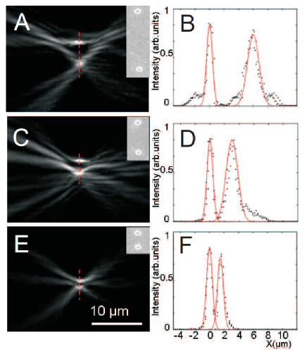
For demonstrating microscopic magnification we now analyze the transverse magnification of our SPP in–plane microscope limitation which is simply given by . We therefore consider again nanoprotrusion pairs located near . While the position of one protrusion is in , the second protrusion is separated by a distance along the direction perpendicular to the microscope symmetry axis of , and m (see Fig. 3). The according LRM images are shown in Figs. 3A, C and E which again display Fourier filtered images, suppressing all SPP components propagating from right to left.
The images of the two protrusion are clearly visible and resolved, even for the smallest distance m. Using the filtered LRM images we obtain transverse cross–cuts of the SPP intensity along the line joining the centers of the two image points, see panels B, D and F of Fig. 4. To guide the eye we include Gaussian fits to the data. Clearly the image of the off–axis protrusion is broader than that of the on–axis protrusion which is due to abberation. Most importantly, however, the observed distances between the image spots are a factor of larger than the distances between the nanoprotrusions, thus directly evidencing the expected factor for the transverse magnification as expected from geometrical optics.
To conclude, we have experimentally demonstrated an in–plane SPP microscope relying on parabolic Bragg mirrors with a spatial resolution of about . In the context of plasmonics this microscopic scheme could complement existing elements as waveguides, mirrors, etc., for the benefit of applications in SPP based imaging, optical sub–wavelength addressing or sensing.
References
- (1) H. Raether, Surface Plasmons (Springer, Berlin, 1988).
- (2) W. L. Barnes, A. Dereux, T. W. Ebbesen, Nature 424, 824 (2003).
- (3) J. C. Weeber, Y. Lacroute, and A. Dereux, Phys. Rev. B. 68, 115401 (2003).
- (4) T. Nikolajsen, K. Leosson, I. Salakhutdinov, and S. I. Bozhevolnyi, Appl. Phys. Lett. 82, 668 (2003).
- (5) H. Ditlbacher, A. Hohenau, D. Wagner, U. Kreibig, M. Rogers, F. Hofer, F. R. Aussenegg, J. R. Krenn, Phys. Rev. Lett. 95, 257403 (2005).
- (6) A. Hohenau, J. R. Krenn, H. Ditlbacher, A. Hohenau, A. Drezet, B. Steinberger, A. Leitner, and F. Aussenegg,, Opt. Lett. 30, 893 (2005).
- (7) Z. Liu, J. M. Steele, W. Srituravanich, Y. Pikus, C. Sun, and X. Zhang, Nano Lett. 5, 1726 (2005).
- (8) H. Ditlbacher, J. R. Krenn, G. Schider, A. Leitner, and F. R. Aussenegg, Appl. Phys. Lett. 81, 1762 (2002).
- (9) L. Yin, V. K. Vlasko-Vlasov, J. Pearson, J. M. Hiller, J. Hua, U. Welp, D. E. Brown, and C. W. Kimball, Nano Lett. 5, 1399 (2005).
- (10) A. Drezet, A. L. Stepanov, H. Ditlbacher, A. Hohenau, B. Steinberger, F. R. Aussenegg, A. Leitner, and J. R. Krenn, Appl. Phys. Lett. 86, 074104 (2005).
- (11) S. I. Bozhevolnyi, V. S. Volkov, E. Deveaux, J. Y. Laluet, and T. W. Ebbesen, Nature 440, 508 (2006).
- (12) By analogy with classical (three-dimensional) optical microscopes which are adapted for imaging of two-dimensional systems located in the object plane, a two-dimensional optical microscope is only able to image one-dimensional systems located along the object line perpendicularly to the optical axis. This limitation is accepted in the present article.
- (13) I. I. Smolyaninov, J. Elliott, A. V. Zayats, C. Davis, Phys. Rev. Lett. 94, 057401 (2005).
- (14) A. Drezet, A. Hohenau, and J. R. Krenn, Phys. Rev. Lett. 98, 209703 (2007).
- (15) M. Born and E. Wolf, Principles of Optics, seventh (expanded) edition (Cambridge University Press, Cambridge, 1999).
- (16) A. Drezet, A. L. Stepanov, A. Hohenau, B. Steinberger, N. Galler, H. Ditlbacher, A. Leitner, F. R. Aussenegg, J. R. Krenn, M. U. Gonzalez, J.-C. Weeber,, Euro. Phys. Lett. 74, 693 (2006).
- (17) M. A. McCord and M. J. Rooks, in Handbook of Microlithography, Micromachining and Microfabrication, Volume 1 edited by P. Rai-Choudhury (SPIE and The Institution of Electrical Engineers, Bellingham, Washington, 1997), pp. 139-249.
- (18) B. Hecht, H. Bielefeldt, L. Novotny, Y. Inouye, and D. W. Pohl, Phys. Rev. Lett. 77, 1889 (1996).
- (19) A. Bouhelier, Th. Huser, H. Tamaru, H. -J. Güntherodt, D. W. Pohl, Fadi I. Baida and D. Van Labeke, Phys. Rev. B. 63, 155404 (2001).
- (20) A. Stepanov, J. R. Krenn, H. Ditlbacher, A. Hohenau, A. Drezet, B. Steinberger, A. Leitner, and F. Aussenegg,, Opt. Lett. 30, 1524 (2005).
- (21) H. Ditlbacher, Ph.D. Thesis, Karl-Franzens University Graz (2003).
- (22) A. Drezet, A. Hohenau, A. Stepanov, H. Ditlbacher, B. Steinberger, N. Galler, F. R. Aussenegg, A. Leitner, J. R. Krenn, Appl. Phys. Lett. 89, 091117 (2006).
Figure: 1//
Confocal parabolic SPP microscope. (A) Scanning electron microscope image. and are the focal points, the focal distances are m and the lines show exemplary SPP paths from to . The inset displays a magnified image of the nanoprotrusions constituting the Bragg mirror structure. The minimum separation between two adjacent mirrors is . (B) LRM image with a single nanoprotrusion at . The laser polarization is indicated by the double arrow. (C) Same as (B) but with a protrusion pair separated by a horizontal distance m. (D) Same as (B) but with a protrusion pair separated by a horizontal distance m. The insets in (B)–(D) show cross–cuts of the SPP intensity along the symmetry axis near , as indicated by the triangles in the images. The cross–cut scale bar is 2 m, the vertical lines are separated by d=1 m (C) and 2 m (D).
Figure 2: //
Magnifying parabolic SPP microscope. (A) Scanning electron microscope image. (B) Two–dimensional dipolar simulation of SPPs propagating inside the parabolic mirrors after launching from . The laser polarization direction is indicated by the double arrow. (C) LRM image corresponding to (B). (D) Magnified LRM image corresponding to the dashed white rectangle in (C) after Fourier filtering of the SPP components propagating from left to right.
Figure 3: //
Microscopic imaging of a nanoprotrusion pair located near using the geometry shown in Fig. 2. A, C and E show the Fourier filtered LRM images for pairs (SEM images shown in the insets) separated by , and m, respectively. The images cover areas corresponding to the same dashed rectangles as in Fig. 2C.B, D, and F show LRM intensity cross–cuts taken along the dashed lines of images A, C and E, respectively. The curves are Gaussian fits to the data.
Figure 1://
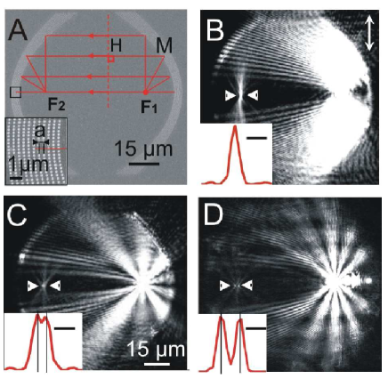
Figure 2://
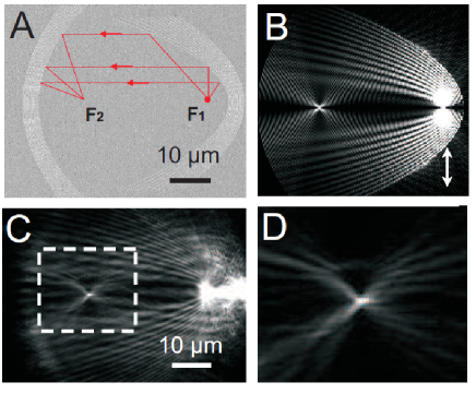
Figure 3://