High resolution magnetostriction measurements in pulsed magnetic fields using Fibre Bragg Gratings
Abstract
We report on a new high resolution apparatus for measuring magnetostriction suitable for use at cryogenic temperatures in pulsed high magnetic fields which we have developed at the Hochfeld-Magnetlabor Dresden. Optical fibre strain gauges based on Fibre Bragg Gratings are used to measure the strain in small ( mm) samples. We describe the implementation of a fast measurement system capable of resolving strains in the order of with a full bandwidth of 47 kHz, and demonstrate its use on single crystal samples of GdSb and GdSi.
pacs:
75.80.+q, 42.81.PaIntroduction
Magnetostriction, the strain response of a material to an external or internal magnetic field, is a thermodynamic tensor quantity that is closely related to the magnetisation.doerr08
Pulsed field facilities provide the highest available magnetic fields for research purposes. Electrical and mechanical noise are significantly higher than in steady fields, however, and the short timescales mean that this noise cannot be effectively averaged. For a typical pulse with a maximum field of T occurring in ms, the field sweep rate can reach T/s. In this demanding environment, fast optical techniques which are immune to electromagnetic interference have significant advantages.
We first review the established methods of measuring magnetostriction in pulsed fields, via capacitance dilatometry or resistive foil strain gauges.
Capacitance dilatometry is the standard technique used for both thermal expansion and magnetostriction measurements in steady fields. The main advantages are that the sample is under only a weak uniaxial stress (applied via springs to keep the capacitor plates in contact with the sample), and that the sensitivity increases the closer the capacitor plates can be approached, while kept in a parallel configuration. Using this technique, the minimum relative change in sample length, , that can be resolved is at 10–20 kHz in pulsed fieldsdoerr08 (or ). Such dilatometers are sensitive to vibration, since the plates are only coupled to each other through the sample, and to electrical noise in the measurement circuit. The limited space inside pulsed field magnets acts as a further constraint on the sensitivity, as the capacitor plates cannot be above a certain size.
Resistive foil gauges bonded directly to the sample have the benefit of relative immunity from vibrations, but suffer from strong magnetoresistance which must be calibrated out or well matched. Their sensitivity is also quite low. For a 1 k strain gauge a resistance change of 2 m must be detected to resolve strains of . The best resolution so far reported with this technique is in pulsed fields.zaragoza06 One further disadvantage is the need to bond strain gauges to the sample surface. The resulting inhomogeneous stress field can affect the response of softer samples. On the other hand, this confers relative immunity from vibration.
An electrically equivalent, but potentially more sensitive technique is to use the the deflection of a piezoresistive cantilever to measure the magnetostriction. This has been recently demonstrated in steady and pulsed high fields.park09 Minimal stress is applied to the sample from contact with the thin cantilever. The sensitivity is as yet unknown, however.
Common to all three techniques described above is the need for an electrical bridge circuit to measure either resistance or capacitance. The metallic components of the bridge circuit, such as wiring and capacitor plates, are subject to self-heating and motion in the rapidly varying magnetic field. In general, these cause both noise and a background signal which can be difficult to subtract from the output.
In contrast, optical fibre strain gauges — or Fibre Bragg Gratings (FBGs) — have the significant advantage of immunity to electromagnetic interference. In addition they combine some of the key advantages of the technologies described above. They can be bonded directly to samples in the same way as resistive foil strain gauges, or can be incorporated into a dilatometer design where they are used both as spring and sensing element.
An FBG is based on a modulation of the refractive index in the core of an optical fibre over some length. The period of this modulation determines the wavelength of light reflected (the Bragg wavelength), while the depth of modulation controls the reflectivity. Longer FBGs have narrower linewidths.othonos97 FBGs have several applications in the fields of telecommunications and sensors, and are a quite mature (and hence cost effective and widely available) technology.
In this article, we discuss the implementation of FBG strain gauge dilatometry at cryogenic temperatures in pulsed high magnetic fields and show that the resolution and interrogation rate are limited only by mechanical noise and the measurement system respectively. We discuss the ways in which strain can be transmitted from the sample under investigation to the FBG. We describe a high resolution, high speed measurement system capable of resolving changes in strain of in pulsed fields.
Methods
The Bragg wavelength, , of an FBG is related to the refractive index of the optical fibre, , and the pitch of the grating, :
| (1) |
The strain and temperature dependence of are given by:
| (2) |
The strain response depends on the collection of terms ,kersey97 which has minimal temperature dependence from 2–300 K for FBGs in silica fibre.james02 and are components of the strain-optic tensor and is the Poisson ratio. The strain response of an FBG is thus linear with the same constant of proportionality at all temperatures, and no calibration is required.
The temperature dependence is controlled by the linear thermal expansion of the optical fibre, , and the change in refractive index with temperature. Both of these become very small at 4He temperatures in silica fibres.reid98
The change in in high magnetic fields has been calculated for the case of polarised light,diego04 and would lead to a shift of around 0.1 nm for an FBG with 1550 nm in silica at 100 T. For the case of unpolarised light, as is used in typical interrogation systems, is not expected to change with magnetic field.
We have chosen to work with FBGs written into the core of single-mode telecommunications optic fibre with nm at room temperature. Since this is an important telecoms band, interrogation equipment and custom FBGs are readily available. The expected shift of is 1.2 pm for 10-6 strain.
The fibre we use has a core diameter of 9 m and a cladding diameter of 125 m. On top of this there is a protective plastic coating. The choice of fibre coating is important for strain-related applications. The mechanical contact between sensor and sample must accurately transmit the strain. Polyimide is a good choice as it sticks to the fibre strongly and there are many epoxies suitable for fixing the FBGs to the test material. Including coating, the FBGs that we use are 0.16 mm in diameter and either 1 or 2 mm long. This is smaller than the majority of commercially available resistive foil strain gauges. A maximum strain of around can be applied to an FBG before the response becomes non-linear or the fibre breaks.smartfibres This is easily large enough for most strain measurements.
There are then many choices of interrogation systems to use, operating on diverse principles. For a good review, see Ref. kersey97, . For measurements in pulsed fields a fast technique ( 10kHz) is necessary, whereas absolute accuracy and long-term stability are less important.
We focus our attention on multi-channel spectrometry, which allows us to detect the complete lineshape of the FBG reflection. If the lineshape is distorted when we affix the FBG to the sample, we can tell if the FBG is under homogeneous stress, i.e. if it is uniformly coupled to the sample along its length.
Our high-resolution FBG interrogation system uses the fastest currently available 1024-pixel InGaAs line array camera sensitive in the wavelength range 900 to 1700 nm, which can read full spectra at 47 kHz.sensorsunlimited The signal-to-noise ratio (SNR) is specified at 5300:1 at full scale where readout and shot noise dominate. Mounted on a fibre-coupled research spectrometer of focal length 550 mm with a 950 l/mm diffraction grating, the 25 m pixel pitch results in a dispersion, , of 0.027 nm/pixel at 1550 nm.
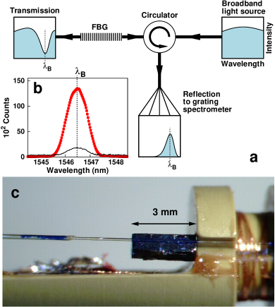
To illuminate the FBG we use a superluminescent-diode-based broadband source with an output power of 60 mW in the wavelength range 1525-1565 nm.denselight The optical circuit is illustrated in Figure 1a. When the source characteristic is measured directly using the spectrometer and camera described above, the SNR reaches 800:1 for full-scale illumination at the shortest integration time of 20.4 s. This is the dominant source of noise in the measurement.
A typical reflection spectrum for a 2 mm FBG is shown in Figure 1b. The uncertainty in the measurement of depends on the way it is calculated from the returned spectra. The standard technique is to calculate the centre of mass of the reflected peak using:
| (3) |
where is the wavelength at the centre of the -th pixel and is the corresponding signal amplitude. For a peak whose full width covers pixels, the r.m.s. error in is approximately:
| (4) |
which has been obtained by a simulation excluding the effects of camera readout noise. Our 2 mm FBGs have a full width at half-maximum (FWHM) of nm and . For the parameters quoted above, this should result in a strain resolution of per reading, or .
One pitfall of this approach is that the incident light power must be increased as the rate of interrogation increases, since the detector must be saturated in a shorter time to achieve the optimal SNR. Fortunately, this power is not dissipated at the sample, rather it is lost at the end of the fibre. If the cryostat is wider than the minimum bend diameter of the fibre (10 mm), its end can be positioned back at the warm end of the cryostat where extra heat input is irrelevant. This means that FBGs can be interrogated at very low temperatures without self-heating, making them suitable for operation in 3He or dilution refrigerators. This is an improvement on electrical measurements, where the excitation must be reduced at low temperatures to avoid self heating, which necessarily reduces the SNR.
Coupling the FBG to the sample can be done in two ways. Our primary consideration is that the experiment should fit inside the various cryostats used for pulsed field measurements, the smallest of which has an internal diameter of 8 mm.
In the simplest case, for a regular sample with a flat surface parallel to the direction of interest, the FBG can be bonded directly to the sample using an appropriate epoxy.hbmepoxy The considerations are the same as for resisitive foil strain gauges: what curing conditions (temperature and pressure) can be tolerated by the sample and FBG, how good is the bond, how accurately can the FBG be aligned along a crystalline axis? Of particular concern is that the sample can experience an inhomogeneous stress due to the epoxy, which therefore distorts the results.
To estimate if this is significant, consider that the Young’s modulus of silica is around 70 GPa. This is similar to many metals. As long as the sample has a much larger cross-sectional area than the optical fibre, the presence of the fibre should not have a significant effect.
The advantages of direct bonding of the FBG to the sample surface are compactness and less sensitivity to mechanical vibrations, which are both concerns when working in small bore pulsed magnets. We have also substituted cyanoacrylate (superglue) in place of a specialised epoxy, with some success. This cures quickly at room temperature and is soluble in acetone, allowing both sample and FBG to be recovered. Figure 1c shows a sample with an FBG glued along its length mounted on a measurement probe.
The alternative is to couple the FBG and sample indirectly, through a dilatometer. In such a dilatometer the sample is clamped into a holder which is mechanically coupled to a free standing FBG sensor. In this way the strain is directly transmitted to the sensor. This is preferable for samples that are intolerant of applied stress, for irregularly shaped samples, or for those which present a different behaviour on the surface than in the bulk.
Results
We have tested the FBG interrogation system described above in pulsed magnetic fields at the Hochfeld-Magnetlabor Dresden. We present results on single-crystal GdSb and GdSi. Owing to the lack of crystal field effects ( = 0 for Gd3+), these two compounds are model systems in which to study complex magnetic two-ion interactions. Both reveal large field-induced magnetostriction.
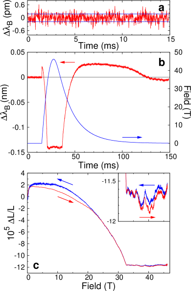
Figure 2 shows the response of the FBG on the GdSb single crystal pictured in Fig. 1c when exposed to the pulsed magnetic field. GdSb is a member of the Gd monopnictide series Gd (=N, P, As, Sb and Bi) with a cubic NaCl-type crystal structure and is characterized by a low carrier density. It orders antiferromagnetically at 23 K and has nearly no magnetic anisotropy. The transition into the field-induced ferromagnetic state proceeds over a wide field range up to 32.6 T followed by a sharp kink when saturation is reached. The magnetostriction measurement shows this transition clearly. Despite the strong spin moment of Gd3+, the change in the magnetic moment is not accompanied by a large lattice effect. The magnetostriction is in the order of only.
The r.m.s. variation of over 15 ms in zero field is shown in Figure 2a to be pm, which corresponds to a strain resolution of . This is three times less than the (optimistic) prediction of Equation 4, and we attribute the difference to a combination of camera readout noise and mechanical vibration.
The noise at high fields is similar to that at zero field. There is some evidence that the sample is heated by the rapidly changing magnetic field, as the value of immediately after the pulse is slightly different to that before. This can be seen in Figure 2b. Since the thermal expansion intrinsic to the optical fibre is negligble below 40 K, it does not contribute significantly to this shift.
The up- and downsweep data match extremely well above 20 T when plotted as a function of magnetic field Figure 2c. Hence any self-heating effect must be limited to long times or low fields. More noise can be seen towards the end of the pulse (see also the inset to Figure 3). This may be due to mechanical vibrations caused by the rapid boiloff of the liquid cryogens in the system during the pulse.
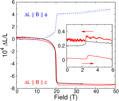
In order to compare the performance FBG-based magnetostriction measurements directly with established techniques, we have measured the same single crystal of GdSi as was used in previous studies. Figure 3 shows the magnetostriction of a single crystal of GdSi measured by bonding a 1 mm FBG to the sample with cyanoacrylate. GdSi crystallizes in the orthorhombic FeB structure. The magnetisation at low field shows anisotropic behaviour due to the interplay between the localised -spins and the conduction electrons.tung05 The magnetisation along the -axis merges with that measured along at about 3 T. Note, that this small anomaly is clearly visible in the magnetostriction curve measured by FBG. At higher field the magnetisation becomes isotropic and, after a spin-flop process, reaches saturation through a first-order-like transition at 20 T. Both processes are clearly visible in the striction curve. The r.m.s. noise level in the GdSi experiment is increased to about pm as the shorter FBG has a wider reflection peak (). The shorter FBG was required as the sample was less than 2 mm long along the -axis.
The comparison of the FBG technique with high steady and pulsed field capacitance dilatometry shown in Figure 3 is very favourable. The high bandwidth allows sharp features to be easily resolved, even on the fast upsweep, while the noise level approaches the steady field results. The FBG signal at 4.8 K is about 5% smaller than the steady field measurements at 4 K. Assuming that the steady field measurements are authoritative, this suggests that the transmission of strain from the sample to the FBG is at worst 95%, which is extremely good. The other possibility is that the slight difference in sample temperature leads to this small quantitative difference in the magnetostriction.
Conclusions
We have demonstrated that FBGs are a very suitable technology for high-accuracy magnetoelastic investigations in small samples under the many simultaneous strong constraints imposed by low temperatures and the highest avalable magnetic fields.
We have developed an FBG interrogation system capable of determining with an r.m.s. error pm and a bandwidth of 47 kHz. We have used this to measure the magnetostriction of small samples glued straightforwardly to FBGs, at cryogenic temperatures in the hostile environment generated by pulsed magnetic fields. We are capable of resolving relative length changes, , as small as (twice the r.m.s. error in interrogation) on a timescale of 20 s, or . This is nearly two orders of magnitude better than was previously possible by other techniques in non-destructive high magnetic fields. This increase in resolution greatly broadens the range of materials whose magnetostriction can be investigated in pulsed magnetic fields.
The FBG based technique has the significant advantage of immunity from electrical noise, and is furthermore quite simple to implement. Since there are no metallic parts, there are no self-heating effects in the magnetic field. No calibration is required. We have shown that the strain is well transmitted from the sample to the FBG.
It should therefore be easy to extend the technique to measure strain transverse to the applied field as well. This can be done simultaneously with a longitudinal measurement using a single fibre containing two FBGs with different glued to the sample in different orientations. No further equipment is required. Similarly, multiple samples can be measured simultaneously using a single fibre, the only limitations being space in the cryostat at the centre of the field and the spectral range of the spectrometer.
The technique is also compatible with very low temperatures (1 K), as in principle no heat is dissipated at the cold end of the cryostat. Inserting the optical fibre into a high-pressure piston-cylinder type clamp cell to measure magnetostriction under pressure in pulsed fields is also a promising possibility. Much potential exists to extend the utility of FBGs further.
Acknowledgements.
This work was supported by the MPG Research Initiative “Materials Science and Condensed Matter Research at the Hochfeld-Magnetlabor Dresden”. We would like to thank M. Bartkowiak and S.W. James for useful discussions and F. Trüller for technical support.References
- (1) M. Doerr, W. Lorenz, T. Neupert, M. Loewenhaupt, N.V. Kozlova, J. Freudenberger, M. Bartkowiak, E. Kampert and M. Rotter, Rev. Sci. Instrum. 79, 063902 (2008).
- (2) P.A. Algarabel, A. del Moral, C. Mart, D. Serrate and W. Tokarz J. Phys.: Conference Series 51 607 (2006).
- (3) J.-H. Park, D. Graf, T. P. Murphy, G. M. Schmiedeshoff and S. W. Tozer, Rev. Sci. Instrum. 80 116101 (2009).
- (4) Andreas Othonos Rev. Sci. Instrum. 68 4308 (1997).
- (5) Alan D. Kersey, Michael A. Davis, Heather J. Patrick, Michel LeBlanc, K. P. Koo, C. G. Askins, M. A. Putnam, and E. Joseph Friebele J. Lightwave Tech. 15 1442 (1997).
- (6) Stephen W. James, Ralph P. Tatam, Andrew Twin, Mungo Morgan and Paul Noonan Meas. Sci. Technol. 13 1535 (2002).
- (7) B. Reid and M. Ozcan Opt. Eng. 37 237 (1998).
- (8) J.L. Arce-Diego, D. Pereda-Cubian and M.A. Muriel J. Opt. A: Pure Appl. Opt. 6 S45 (2004).
- (9) See for example: http://www.smartfibres.com/docs/SmartFBG.pdf
- (10) Goodrich ISR (Sensors Unlimited) model SU1024LDH-1.7RT-0500/LC
- (11) Denselight Semiconductors model DL-ASE-CW-CSC183A.
- (12) For example, EP310-S from HBM GmbH.
- (13) L. D. Tung, M. R. Lees, G. Balakrishnan, D. McK. Paul, P. Schobinger-Papamentellos, O. Tegus, P. E. Brommer, and K. H. Buschow Phys. Rev. B 71 144410 (2005).