Impact ionization fronts in Si diodes: Numerical evidence of superfast propagation due to nonlocalized preionization
Abstract
We present numerical evidence of a novel propagation mode for superfast impact ionization fronts in high-voltage Si -- structures. In nonlinear dynamics terms, this mode corresponds to a pulled front propagating into an unstable state in the regime of nonlocalized initial conditions. Before the front starts to travel, field-ehanced emission of electrons from deep-level impurities preionizes initially depleted base creating spatially nonuniform free carriers profile. Impact ionization takes place in the whole high-field region. We find two ionizing fronts that propagate in opposite directions with velocities up to 10 times higher than the saturated drift velocity.
pacs:
72.20.Ht,85.30.-z,Superfast impact ionization fronts travel with velocity higher than the saturated drift velocity . Excitation of such fronts is the fastest non-optical method to modulate conductivity of a high-voltage semiconductor structure. LEV05 ; Si ; GaAs This method has important pulse-power application.GRE89 ; FOC97 ; Kardo Recently, we proposed a novel mode of superfast front propagation in semiconductor structures: a pulled front propagating into unstable state in the regime of nonlocalized initial conditions. ROD08 This mode is expected to appear in -- structures with a relatively low base doping level. The propagation mechanism is qualitatively different from that for the well-known TRAPATT-like propagation mode, DEL70 ; KYU07 ; ROD07 widely considered as a most feasible mechanism of the superfast switching of high-voltage pulse-power devices. LEV05 For the impact ionization front the term “nonlocalized initial conditions” SAA03 means a small free carriers concentration that decreases in the direction of front propagation. It has been suggested ROD08 that such preionization of the initially depleted base may be created by field-enhanced electron emission from deep-level centers.ROD05 Numerical simulations presented in the Letter confirms this suggestion and provide the first evidence of superfast front propagation due to nonlocalized preionization in realistic Si -- structures used in pulse-power applications.
Process-induced (PI) deep-level centers in Si are double-charged donors with ionization energies 0.28 eV (U level) and 0.54 eV (M level).SAH ; sulfur Originally thought of as recombination centers, SAH PI centers turned out to be deep electron traps. sulfur As they do not influence the life-time of nonequilibrium carriers (the most carefully controlled parameter of the commercial material), their presence in high-purity Si is “hidden”.sulfur In high voltage structures used in power applictations PI centers appear in concentration (Ref. sulfur, ). Field-enhanced ionization of PI centers is a potential mechanism of determenistic low-jitter triggering of the ionizing front in high-voltage structures. ROD05 In the simplest case of low temperatures ( K) the emission rate depends on the electrical field as(Ref. ROD05, )
| (1) |
where , eV is the binding energy (U level), is Bohr energy in semiconductor, is the effective electron mass and is the elementary charge. Field-enhanced ionization of PI centers has a characteristic threshold (Ref.ROD05, ) that exceeds the threshold of band-to-band impact ionization . It is important that because electrical field in the base should be increased above before impact ionization starts.ROD05
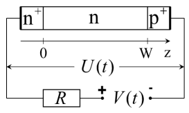
Superfast triggering occurs when a sharp voltage ramp is applied to reversely biased Si -- structure connected to the voltage source in series with load resistance (Fig. 1). The applied voltage is modelled as , where the inital voltage is chosen so that the base is fully depleted at . We assume that - and - junctions are sharp and restict modelling to the base. To describe the dynamics of electron and hole concentrations , and electrical field , we use the standard one-dimensional drift-diffusion model together with the Poisson equation and the Kirchoff equation for the external circuit. The generation term includes the cut-off that eliminates unphysical multiplication at low concentrations .ROD02 We refer to Ref. ROD02, for the details of the model and of the numerical method used. The generation term additionally incorporates field-enhanced emission of free electrons from PI centers with a rate given by Eq. (1). We use the following set of structure and circuit parameters: the base length , dopant concentration , , cross-section area , load resistance Ohm, initial bias kV. The respective stationary breakdown voltage is about 1.2 kV. We choose , as in Refs. ROD02, ; ROD02a, .
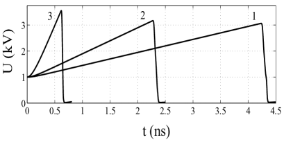
In Fig. 2 we show the voltage over the diode during switching process. At the first stage nearly follows the applied voltage . Then, sharply drops and the current flowing through the diode increases. The triggering time is close to 100 ps and decreases with increase of the voltage ramp . This is 10 times faster than the drift time ns. Such superfast switching has been observed in the whole range of actual voltage ramps 0.5…10 kV/ns. Although the transient looks similar to the earlier numerical results for TRAPATT-like BIL83 ; KAR96 ; FOC97 ; GAU98 ; ROD02 or tunneling-assisted ROD02a ; RUK05 impact ionization fronts, the inner dynimics turns out to be qualitatively different.
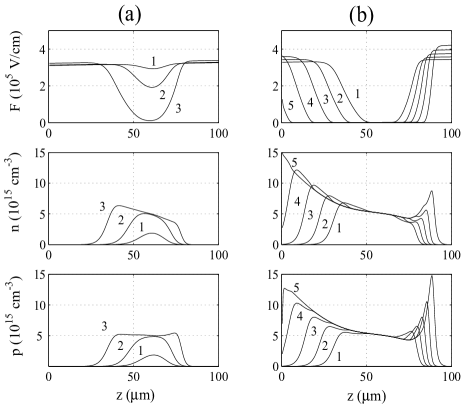
In Fig. 3 we show the inner dynamics for kV/ns. Due to the higher electrical field, the emission of electrons from PI centers is most efficient near - junction. Free electrons drift to the left and multiplicate by the band-to-band impact ionization. Due to this drift, the maximum of the concentration profile is shifted from the - junction into the base [Fig. 3(a)]. Screening begins when concentrations and overcome . Eventually, the avalance multiplication creates the initial plasma layer that fully screens the applied electrical field [Fig. 3(a), curve 3]. Afterwards, the plasma layer expands due to propagation of two ionizing fronts travelling in opposite directions [Fig. 3(b)].
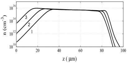
The left and the right (negative and positive) fronts travel with velocities and , respectively. Both fronts propagate into the areas where the electrical field is nearly constant in space and varies in the interval from to V/cm, nearly 2 times larger than . The small amount of free cariers is present everywhere (Fig. 4). Hence avalance multiplication also goes on all over the high-field region. These conditions are favorable for quasiuniform breakdown. The reason why the front-like solution nevertheless occurs is the nonuniform profile of preionization: the concentration of free carriers in the high-field region decreases in the direction of front propagation. This decay happens to be nearly exponential with characteristic exponents and for negative and positive fronts, respectively (Fig. 4). In nonlinear dynamics, such fronts are known as pulled fronts propagating into unstable state in the regime of nonlocalized initial conditions. SAA03
Let us compare the numerical results with analytical predictions for front velocity and plasma concentration made in Ref. ROD08, for the simplified model where electrons and holes have the same impact ionization coefficients and . For sufficiently small exponent , the front velocity is given by
| (2) |
where is the impact ionization coefficient in the high field region the front propagates to. In Si in strong electrical fields impact ionization by holes is much weaker than by electrons. Therefore shall be replaced by in the nominator of Eq. (2). The numerical value is for . Eq. (2) is applicable if , where corresponds to so called marginally stable front SAA03 and is explicitly determined by , diffusion coefficient and (see Ref. ROD08, ). Simple calculation shows that . Hence, the condition is met for the case under consideration, and we obtain analytical estimates and for the negative and positive fronts shown in Figs. 3,4, respectively, in good agreement with numerical results.
For the symmetrical model, the plasma concentration behind the front is given by where the ionization coefficient is approximeted as (Ref. ROD08, ). Removing again the factor of 2 and taking the numerical values , V/cm for electrons in Si, we get for the actual electrical field V/cm, in good agreement with numerical results.
The velocity of the convential TRAPATT-like front is determined by the size of impact ionization zone. DEL70 ; KYU07 ; ROD07 In contrast, the velocity of the pulled front in the regime of nonlocalized initial conditions is determined by the slope of the preionization profile, while the size of impact ionization zone coincides with the total size of the high-field region. Consequently, the pulled fronts shall be expected in structures with moderate doping where the condition is met all over the high-field region. However, a certain level of the base doping is crucial because it leads to the slope of the electrical field in the depleted base. Due to this slope the field-enhanced ionization of PI centers is spatially nonuniform and creates decaying profile of preionization. In particluar, in -- structures nonlocalized initial conditons for the pulled front propagation cannot be created by deep-level impurities. For large the convential TRAPATT-like mode DEL70 ; KYU07 ; ROD07 occurs, but the cross-over to the pulled mode is possible at the last stage of front propagation when the condition is met everywhere.
We are indebted to W. Hundsdorfer who has developed numerical tools used in the simulations. This work was supported by Russian Academy of Science in the framework of the project “Power semiconductor electronics and pulse technology”. P. Rodin is grateful to A. Alekseev for hospitality at the University of Geneva and acknowledges the support from the Swiss National Science Foundation.
References
- (1) Electronic address: rodin@mail.ioffe.ru
- (2) M. Levinshtein, J. Kostamovaara, S. Vainshtein, Breakdown Phenomena in Semiconductors and Semiconductor Devices (Word Scientific, 2005).
- (3) I.V. Grekhov and A.F. Kardo-Sysoev, Sov. Tech. Phys. Lett. 5, 395 (1979).
- (4) Zh.I. Alferov, I.V. Grekhov, V.M. Efanov, A.F. Kardo-Sysoev, V.I. Korol’kov, and M.N. Stepanova Sov. Tech. Phys. Lett. 13, 454 (1987).
- (5) I.V. Grekhov, Solid-State Electron. 32, 923 (1989).
- (6) R.J. Focia, E. Schamiloghu, C.B. Fledermann, F.J. Agee and J. Gaudet, IEEE Trans. Plasma Sci. 25, 138 (1997).
- (7) A.F. Kardo-Susoev, New Power Semiconductor Devices for Generation of Nanosecond Pulses, in Ultra-Wideband Radar Technology, edited by James D. Taylor, CRC Press, Boca Raton, London, New York, Washington, 2001, pp.205-209.
- (8) P. Rodin, A. Minarsky, I. Grekhov, Appl. Phys. Lett. 93, 013503 (2008).
- (9) P. Rodin and I. Grekhov, Appl. Phys. Lett. 86, 243504 (2005); P. Rodin, A. Rodina, and I. Grekhov, J. Appl. Phys. 98, 094506 (2005).
- (10) B.C. Deloach and D.L. Scharfetter, IEEE Trans. Electron Devices ED-20, 9 (1970).
- (11) A.S. Kyuregyan, Semiconductors 41, 737 (2007).
- (12) P. Rodin, U. Ebert, A. Minarsky and I. Grekhov, J. Appl. Phys. 102, 034508 (2007).
- (13) W. van Saarloos, Physics Reports 386, 29 (2003)
- (14) L.D. Yau and C.T. Sah, Solid-State Electronics 17, 193(1974); J. Apl. Phys. 46, 1767 (1975).
- (15) E.V. Astrova, V.B. Voronkov, V.A. Kozlov and A.A. Lebedev, Semicond. Sci. Technol. 13, 488-495 (1998).
- (16) Yu.D. Bilenko, M.E. Levinstein, M.V. Popova and V.S. Yuferev, Sov. Phys. Semicond. 17, 1156 (1983).
- (17) A.F. Kardo-Susoev and M.V. Popova, Sov. Phys. Semicond. 30, 431 (1996).
- (18) H. Jalali, R. Joshi, and J. Gaudet, IEEE Trans. Electron Devices 45, 1761-1768(1998).
- (19) P. Rodin, U. Ebert, W. Hundsdorfer, and I. Grekhov, J. Appl. Phys. 92, 1971 (2002).
- (20) P. Rodin, U. Ebert, W. Hundsdorfer, and I. Grekhov, J. Appl. Phys. 92, 958 (2002).
- (21) S.K. Lyubutin, S.N. Rukin, B.G. Slovikovsky, S.N. Tsyranov, Tech. Phys. Lett. 31, 196 (2005).