The potential for extending the spectral range accessible to the European XFEL down to 0.05 nm
Abstract
Specifications of the European XFEL cover a range of wavelengths down to 0.1 nm. The baseline design of the European XFEL assumes standard (SASE) FEL mode for production of radiation i.e. only one photon beam at one fixed wavelength from each baseline undulator with tunable gap. Recent developments in the field of FEL physics and technology form a reliable basis for an extensions of the mode of operation of XFEL facilities. This paper explores how the wavelength of the output radiation can be decreased well beyond the European XFEL design, down to nm. In the proposed scheme, which is based on the use ”fresh bunch” technique, simultaneous operation at two different wavelengths possible. It is shown that one can generate simultaneously, in the same baseline undulator with tunable gap, high intensity radiation at nm at saturation, and high intensity radiation around nm according to design specifications. We present a feasibility study and we make exemplifications with the parameters of SASE2 line of the European XFEL.
DEUTSCHES ELEKTRONEN-SYNCHROTRON
Ein Forschungszentrum der
Helmholtz-Gemeinschaft
DESY 10-005
January 2010
The potential for extending the spectral range accessible to the European XFEL down to 0.05 nm
Gianluca Geloni,
European XFEL GmbH, Hamburg
Vitali Kocharyan and Evgeni Saldin
Deutsches Elektronen-Synchrotron DESY, Hamburg ISSN 0418-9833 NOTKESTRASSE 85 - 22607 HAMBURG
1 Introduction
Three X-ray Free-Electron Lasers (XFELs), LCLS LCLS , SCSS SCSS , and the European XFEL XFEL are currently under commissioning or under construction. These machines are based on the Self-Amplified Spontaneous Emission (SASE) process KOND -PELL . Lasing at wavelength as short as nm has been recently demonstrated at LCLS LCLS2 , together with operation with electron bunch durations of less than fs DING . Also, at LCLS saturation has been reached within 20 undulator cells, out of the 33 available. This result has been enabled by the high-performance beam-formation system at LCLS, which works as in the ideal operation scenario.
This optimal scenario should be exploited to provide users with the best possible fruition opportunities. Elsewhere OUR0 we suggested to use the extra-undulator length available to provide two short (sub-ten fs), powerful (ten GW-level) pulses of coherent x-ray radiation at different wavelengths for pump-probe experiments at XFELs, with minimal hardware changes to the baseline setup.


In principle, the scheme proposed in OUR0 can be easily extended to generate radiation down to nm. The scheme is illustrated in Fig. 1. The first two parts of the undulator generate radiation at nm, based on a fresh bunch technique according to the method illustrated in OUR0 . The heading half of the bunch is seeded by the radiation produced in the first part of the undulator, and saturates in the second part, while the rear part of the bunch enters the linear regime in the SASE mode. As a result, the rear part of the electron bunch is still suitable for the SASE process in the third undulator part. After the second part we still have about m of undulator available for SASE2, so that we can reach a high power level at a different wavelength, in our case nm. In particular, our calculations are performed for SASE2 assuming that the third part of the undulator is modules-long, corresponding to m. Results are shown in Fig. 2, which include the radiation pulse at nm, as discussed in OUR0 and the short wavelength emission at nm. Fig. 2 demonstrates that two femtosecond, ten GW level pulses of coherent x-rays with two different colors at nm and nm can be generated with this method. The advantage of this method is in the simple hardware required (only a short magnetic chicane) and in the possibility of independently tuning the wavelengths of both pulses. However, a fairly long undulator is needed. Note that the LCLS is equipped with a shorter undulator than SASE2. Therefore, for LCLS the requirement of a shorter undulator is of crucial importance, while for SASE2 this option can be practically realized.
In this paper we propose a scheme for the simultaneous generation of two maximal-power pulses of radiation around - nm and at nm, using an undulator which is about m shorter than the nominal SASE2 length, so that the extra-available undulator length can be kept for other purposes. This scheme is especially important for shorter undulators like for SASE1 and LCLS, which have fixed gap and can operate at fixed wavelength only. Technically, the gap of these undulators can be tuned to nm and fixed once and for all. For this kind of undulators our scheme gives the possibility to tune and fix the gap so to keep the design mode operation at - nm and add an extra operation-mode at nm. By this, we answer the interest of the scientific community towards shorter operation wavelengths, which would e.g. enable better spatial resolution in elastic x-ray scattering experiments, providing at the same time less photoelectric absorption, longer penetration depth, less damage and larger scattering volume MASS .

The overall idea is sketched in Fig. 3. In the first part of the undulator, SASE radiation is produced at nm in the linear regime and in the short-bunch operation mode, according to the parameters in Table 1, and described in more detail in OUR0 . At the next step, the electron beam passes through an optical-delay stage composed by a mirror chicane and a magnetic chicane. The optical delay-stage delays the photon beam with respect to the electrons of about half of the bunch length. The magnetic chicane performs two actions. First, it allows for the installation of the mirror chicane. Second, the strength of magnetic chicane as dispersion section is sufficient for suppression of the beam bunching OUR0 . As a result, the amplification process in the second undulator section starts with a ”fresh” electron beam, and with radiation produced by the first undulator section. This is the essence of the ”fresh bunch” technique which was introduced in HUAYU -SAL2 . Subsequently, in the second part of the undulator the seeded half of the electron beam saturates within a short distance, while the non-seeded half of the electron beam lases in the linear regime only and remains unspoiled. Superimposed to the main first-harmonic pulse there is a percent-level ( MW-level) third-harmonic pulse at nm. The third-harmonic component is superimposed to the non-seeded half of the electron beam by delaying the electrons with respect to the photon beam with the help of a magnetic chicane between the second and the third part of the undulator. Then, the fresh bunch half of the bunch is fed into the third undulator part together with the first and the third harmonic pulse, Fig. 3. The third undulator part is tuned at nm, so that the first harmonic pulse is not resonant, while the MW-level third-harmonic pulse acts as seed and enables production of a GW-level pulse at nm at the exit of the third undulator part.
| Units | Short pulse mode | |
| Undulator period | mm | 47.9 |
| Undulator length | m | 256.2 |
| Length of undulator segment | m | 5.0 |
| Length of intersection | m | 1.1 |
| Total number of undulator cells | - | 42 |
| K parameter (rms) | - | 1.201-2.513 |
| m | 17 | |
| Wavelength | nm | 0.05 - 0.15 |
| Energy | GeV | 17.5 |
| Charge | nC | 0.025 |
| Bunch length (rms) | m | 1.0 |
| Normalized emittance | mm mrad | 0.4 |
| Energy spread | MeV | 1.5 |
2 Feasibility study
In the following we describe the outcomes of computer simulations using the code Genesis GENE .
2.1 First stage
In the first undulator part, which is 7 cells long, each consisting of a m-long undulator segment and a m-long intersection, for a total length of m. The beam power distribution is shown in Fig. 4. The electron beam energy loss and the induced energy spread are shown in Fig. 5. A short (sub femtosecond) pulse of radiation is produced in the linear regime ( MW level). Calculations are identical to the first stage of the pump-probe scheme reported in OUR0 .


2.2 Optical delay
At variance with respect to the pump-probe scheme in OUR0 , the present scheme uses from the very beginning an optical delay stage. This choice is justified by the larger glancing angle for the radiation at nm, which is about mrad, with respect to that at nm, which is mrad only. The idea is to install a mirror chicane between the first and the second part of the undulator, as shown in Fig. 6. Issues concerning heat load and size of the mirror have already been discussed in OUR0 .
Of course, in order to install the mirror chicane one needs to first create an offset for the electron trajectory, meaning that a magnetic chicane should be inserted at the position of the mirror-chicane, Fig. 7. Such chicane has also the function of washing out electron beam density modulations on the nm-scale. Issues concerning this possibility have also been discussed in OUR0 .
The mirror chicane can be built in such a way to obtain a delay of the SASE pulse of about fs. This is enough to compensate a bunch delay of about fs from the magnetic chicane, and to provide the temporal shift in the range fs, as shown in Fig. 8. It should be noted that the distance between quadruples in FODO lattice is m, while in our scheme the length of chicane is m only, so that the focusing system is not perturbed.


As a result of the passage through the magnetic chicane, the photon beam is delayed with respect to the electron beam of about m. The electric field fed into the simulation of the second part of the undulator is shown in Fig. 9. The electron beam used is generated according to the energy spread and energy loss distributions in Fig. 5, similarly as done in OUR0 .
2.3 Second stage
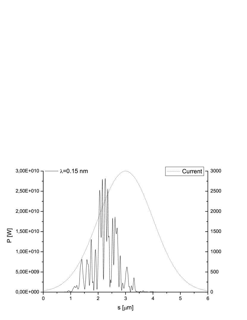
In the second undulator part, the seeded half of the electron bunch reaches saturation with ten GW power level. The second undulator part is taken to be another cells long. The output power distribution and spectrum is shown in Fig. 10 and Fig. 11, while energy loss and energy spread are plotted in Fig. 12. The right part of the electron bunch produces SASE radiation in the linear regime only, which is negligible.


2.4 Magnetic delay
Together with the saturated first harmonic pulse, the radiation pulse produced by the seeded (left) half of the electron bunch also includes some percent-level third harmonic contents. Letting the bunch through a short chicane, we effectively let the radiation pulse slip forward111In these simulations, the shift amounts to m. and seed the fresh (right) half of the electron bunch, Fig. 13. The effect of the chicane on the relative position between electrons and photons is shown in Fig. 14. First and third harmonic pulses will be superimposed, but if the third part of the undulator is resonant with the third harmonic only, the first harmonic will not be of interest as concerns the SASE process. As a result, in our simulations, we simulate the magnetic delay by extracting the third harmonic content and shifted it right with respect to the electron bunch. The result is shown in Fig. 15.


2.5 Third stage
Following the optical delay, we model the third part of the undulator, which is cells-long ( m), by feeding the third harmonic seed in Fig. 15 into the simulation code. Similarly as before, the electron beam used is generated according to the energy spread and energy loss distributions in Fig. 12.


2.6 Results
Fig. 14 and Fig. 16 constitute our main results. Note that the two pulses at nm and nm are actually superimposed one on top of the other. Like in the case discussed elsewhere OUR0 , one faces the task of transport and utilization of the two radiation pulses to the experimental station. Transport can be performed with the same optics without problems, but utilization of the two pulses implies the capability of separating the two pulses at the experimental station. Investigating this capability goes beyond the scope of this paper.
3 Conclusions
In this paper we propose a technique to extend the baseline wavelength range of the European XFEL up to nm. Simultaneously, together with the short-wavelength pulse, a longer wavelength pulse of similar duration and power is produced at nm.
Two recent developments in FEL physics have made our technique feasible. First, the lasing of LCLS and the possibility of working in the low-charge mode of operation LCLS2 , DING . Second, the invention in OUR0 of a new kind of fresh bunch technique HUAYU allowing for the production of two color pulses with similar frequency, which relies on a single electron bunch passing two parts of the same undulator setup, separated with magnetic delay. Also the scheme proposed in this paper is based on letting the same electron bunch radiate in separate undulator stages separated with optical delays and magnetic chicane.
The technique itself is fairly straightforward. Following the first stage, where seed radiation is produced at nm in the linear regime, an optical delay stage enables one half of the electron beam to interact with the seed. After saturation at the end of the second stage the third harmonic component of the radiation is further used as a seed in the third stage, which is resonant at 0.05 nm wavelength. This undulator is long enough (70 m) to reach saturation at the wavelength of 0.05 nm. In the third undulator the radiation at 0.15 nm plays no role and is diffracted out of the electron beam.
As the method in OUR0 , the present method requires very limited hardware too and is low cost. Moreover, it carries no risks for the operation of the machine in the baseline mode. Even though we discuss the case of the European XFEL, our technique may be taken advantage of by other facilities as well.
4 Acknowledgements
We are grateful to Massimo Altarelli, Reinhard Brinkmann, Serguei Molodtsov and Edgar Weckert for their support and their interest during the compilation of this work.
References
- [1] J. Arthur et al. Linac Coherent Light Source (LCLS). Conceptual Design Report, SLAC-R593, Stanford (2002) (See also http://www-ssrl.slac.stanford.edu/lcls/cdr).
- [2] Tanaka, T. & Shintake, T. (Eds.): SCSS X-FEL Conceptual Design Report. Riken Harima Institute, Hyogo, Japan, 2005 (see also http://www-xfel.spring8.or.jp).
- [3] M. Altarelli et al. (Eds.), XFEL: The European X-Ray Free-Electron Laser. Technical Design Report, DESY 2006-097, DESY, Hamburg (2006) (See also http://xfel.desy.de).
- [4] A.M. Kondratenko and E.L. Saldin, Part. Accelerators 10 (1980) 207.
- [5] Ya.S. Derbenev, A.M. Kondratenko and E.L. Saldin, Nucl. Instrum. and Methods 193 (1982) 415.
- [6] R. Bonifacio, C. Pellegrini and L. Narducci, Opt. Commun. 50 (1984) 373.
- [7] J.B. Murphy and C. Pellegrini, Nucl. Instrum. and Methods A 237 (1985) 159.
- [8] P. Emma, First lasing of the LCLS X-ray FEL at 1.5 , in Proceedings of PAC09, Vancouver, to be published in http://accelconf.web.cern.ch/AccelConf/
- [9] Y. Ding et al., Phys. Rev. Lett. 102, 254801 (2009).
- [10] G. Geloni, V. Kocharyan and E. Saldin, ”Scheme for femtosecond-resolution pump-probe experiments at XFELs with two-color ten GW-level X-ray pulses”, DESY 10-004 (2010).
- [11] M. Altarelli, Report on the workshop ”Science drivers for Hard X-Ray Upgrades to LCLS”, (2009).
- [12] I. Ben-Zvi and L.H. Yu, Nucl. Instr. and Meth. A 393, 96 (1997).
- [13] E. Saldin, E. Schneidmiller and M. Yurkov, Opt. Commun. 212, 377 (2002).
- [14] E. Saldin, E. Schneidmiller and M. Yurkov, Opt. Commun., 239, 161 (2004).
- [15] M. Altarelli, et al. (Eds.) XFEL, The European X-ray Free-Electron Laser, Technical Design Report, DESY 2006-097, Hamburg (2006).
- [16] S Reiche et al., Nucl. Instr. and Meth. A 429, 243 (1999).