Deposition of Na Clusters on MgO(001)
Abstract
We investigate the dynamics of deposition of small Na clusters on MgO(001) surface. A hierarchical modeling is used combining Quantum Mechanical with Molecular Mechanical (QM/MM) description. Full time-dependent density-functional theory is used for the cluster electrons while the substrate atoms are treated at a classical level. We consider Na6 and Na8 at various impact energies. We analyze the dependence on cluster geometry, trends with impact energy, and energy balance. We compare the results with deposit on the much softer Ar(001) surface.
pacs:
34.50.Lf, 36.40.Sx, 68.49.FgI Introduction
A major branch of present-days cluster research comprises clusters in contact with solid surfaces, for an overview see, e.g., Meiwes-Broer (2000); Binns (2001); Meiwes-Broer (2006); Meiwes-Broer and Berndt (2007). The interaction of these two entities gives rise to a rich scenery of effects such as, e.g., chemical reactions at surfaces Lambert and Pacchioni (1997); Watanabe et al. (2006); Rösch et al. (2004), particularly, catalytic applications Heiz and Landman (2006); Freund et al. (2000); Sanchez et al. (1999), or modified optical responseDiederich et al. (2002); Pinchuk et al. (2004); Fehrer et al. (2007). One crucial aspect here is the process of cluster deposition which is relevant for synthesis and for analysis of clusters in contact with surfaces. Moreover, the deposition dynamics as such is an interesting and demanding process due to the subtle interplay of the impact of interface energy, electronic band structure of the substrate, and surface corrugation. Accordingly, there is a wealth of investigations on cluster deposition, experimentally oriented Li et al. (1991); Schaefer et al. (1995); Kuhrt and Harsdorff (1995); Bromann et al. (1996); Fedigro et al. (1998); Lau et al. (2003); Sieber et al. (2006); Duffe et al. (2007), theoretically with molecular dynamics (MD) techniques Xirouchaki and Palmer (2002); Cheng and Landmann (1993); Haberland et al. (1993); Webb (2007); Järvi et al. (2007) or more detailed quantum mechanical methods Häkkinen and Manninen (1996a, b); Moseler et al. (2002); Ipatov et al. (2003, 2004); Inntam et al. (2006); Dinh et al. (2007), for reviews see Jensen (1999); Binns (2001); Heiz and Landman (2006). Although addressing the same physical processes, these various theoretical approaches, relying on different approximations, often provide useful complementary information. Recently, we have investigated deposition dynamics of Na clusters on Ar(001) surface Dinh et al. (2007, 2008, 2009). The aim of this paper is to continue these theoretical studies now considering deposition dynamics of Na clusters on a much ”harder” surface than Ar, namely MgO(001) insulator surfaces. The structural properties and optical response of Nan on MgO have already been studied in great detail in using the present computational approach Bär et al. (2007). Both Ar and MgO are similar in that they are both insulators with a large band gap, but they differ significantly in other important properties. There are, however, large differences in other properties. Ar is a Van-der-Waals bound material, thus very soft with little surface corrugation. On the other hand, MgO is an ionic crystal, well bound and with large surface corrugation. It is thus most interesting to see how deposition dynamics proceeds in that case, as such, and at variance with the Ar case.
The theoretical description of clusters on surfaces is very involved due to the huge number of degrees-of-freedom of these systems. This holds the more so for dynamics. The vast majority of theoretical studies thus resorts to MD simulations using effective force fields between the atoms, as mentioned above Xirouchaki and Palmer (2002); Cheng and Landmann (1993); Haberland et al. (1993); Webb (2007); Järvi et al. (2007); Jensen (1999). These are comparatively inexpensive and can provide a pertinent picture of the leading atomic transport processes. Metal clusters are more than an ensemble of atoms because they held together by delocalized bonds (due to a common electron cloud); in consequence they show pronounced shell effects de Heer (1993); Brack (1993); Bjornholm and Borggreen (1999). This makes a quantum mechanical description of cluster dynamics advisable. Most of the fully quantum mechanical pictures make compromises in concluding on dynamical features from a series of static calculations. A true Born-Oppenheimer MD for deposition of Pd clusters on MgO substrate can be found in Moseler et al. (2002). The enormous expense of such high level calculations limits the size of the systems, particularly the size of the representative for the substrate. On the other hand, there are many situations in which the substrate is much more inert than the cluster. Our test case of Na clusters on MgO(001) belongs to that class. This suggests to use a hierarchical description where the cluster electrons are treated quantum-mechanically by full Time-Dependent Density-Functional theory (TDDFT) while the substrate atoms are handled at a lower level of refinement by classical motion. This modeling belongs to the family of coupled Quantum-Mechanical with Molecular-Mechanical methods (QM/MM) which are often used in other fields as, e.g., bio-chemistry Field et al. (1990); Gao (1996); Gresh and Garmer (1996) or surface physics Mitchell and Fincham (1993); Nasluzov et al. (2001). In earlier studies, we developed and applied a QM/MM model for Na clusters in contact with Ar Gervais et al. (2004); Fehrer (2006); Fehrer et al. (2005a); Dinh et al. (2008, 2009). We have shown that it was most crucial to include properly the dynamical polarizability of the substrate when exploring truly dynamical processes as we aim at. Recently, we extended the modeling to Na clusters on MgO surfaces, again including dynamical polarizability Bär et al. (2007). Here we take up that model and apply it to a study of deposition dynamics. We will consider Na6 and Na8 as test cases. These two clusters have very different geometries and binding properties which allows to explore qualitatively the impact of cluster properties on the deposition process.
The paper is organized as follows: In section II, we summarize the QM/MM model for Na clusters on MgO. Section III presents results tracking the detailed dynamics in terms of trajectories and analyzing the processes with respect to energy transfer and energy balance. Conclusions are summarized in section IV.
II Brief summary of the model
II.1 The degrees-of-freedom
| valence electrons of the Na cluster | |
| positions of the Na+ ions | |
| positions of the O cores | |
| center of the O valence cloud | |
| positions of the Mg2+ cations |
The hierarchical QM/MM model has been detailed in Bär et al. (2007). We review that here briefly. The various constituents and their degrees-of-freedom are summarized in table 1. The Na cluster is treated in standard fashion Calvayrac et al. (2000); Reinhard and Suraud (2003). Valence electrons are described in terms of single-particle wavefunctions and the complementing Na+ ions are handled as charged classical point particles characterized by their positions , see upper block of table 1. The electrons are described by TDDFT at the level of the local density approximation (LDA) The substrate is composed of two species: Mg2+ cations and O2- anions. The cations are electrically inert and can be treated as charged point particles; they are labeled by . The anions are easily polarizable, an aspect which is described by allowing for two constituents: a valence electron distribution (labeled by ) and the complementing core (labeled by ). Each of these three types of constituents is described as a classical degree-of-freedom in terms of positions , see the lower block of table 1. The difference represents the electrical dipole moment of the O2- anion and is thus allowed, by construction, to explicitly evolve in time, as a function of the local electric field due to all constituents of the system at a given instant.
The combined system is sorted in four stages of decreasing activity, as sketched in figure 1. The Na cluster is treated at the highest level of theory with full TDLDA-MD. The Mg and O ions of the substrate are arranged in fcc crystalline order corresponding to bulk MgO, with a lattice parameter of 7.94 . All dynamical degrees-of-freedom for Mg and O, as listed in table 1, are taken into account in an active cell of the MgO(001) surface region underneath the Na cluster, denoted “zone I” in the sketch. The active cell is continued by an outer region of MgO material (“zone IIa”) where the ionic centers of Mg and O are kept fixed, while oxygen dipoles still remain active degrees-of-freedom. Thus zone I together with zone IIa constitute the “active cell”. Anything farther out (“zone IIb”) is totally frozen at crystalline configuration and only its Madelung potential is considered. The effect of the outer region on the active part is given by a time-independent shell-model potential Dick and Overhauser (1958); the actual parameters of this force field were adopted from Nasluzov et al. (2001).

The active cell consists of three layers, each containing square arrangements of 242 Mg2+ cations and 242 O2- anions. The ions in the lowest layer are fixed at the bulk structure to prevent them from relaxing and forming an artificial second surface. The volume where ions and electrons are mobile (zone I) has a diameter of 24 , all layers together (zone I+IIa) extend to 42 from the surface. Bulk structure farther out is modeled by the Madelung potential. Checks with models of a larger number of layers showed that three layers provide an adequate description of the very inert MgO material. (The soft Ar(001) substrate, used for comparison later on, is more critical and requires at least four active layers plus two frozen ones.)
II.2 The energy
The total energy is composed as where describes an isolated Na cluster, the MgO(001) substrate, and the coupling between the two subsystems. For , we take the standard TDLDA-MD functional as in previous studies of free clusters Reinhard and Suraud (2003); Calvayrac et al. (2000) including an average self-interaction correction Legrand et al. (2002). The energy of the substrate and the coupling to the Na cluster consist of long-range Coulomb energy and some short-range repulsion which is modeled through effective local core-potentials Nasluzov et al. (2001). To avoid the Coulomb singularity and to simulate the finite extension of Mg2+ and O2- ions, we associate a smooth charge distribution with each of these ionic centers. We associate a similar smooth charge distribution to the O2- valence cloud as well. This altogether yields a soft Coulomb potential to be used for all active particles.
II.3 Calibration of the QM/MM model
The calibration of the whole model has to address three issues: The cluster as such, the environment as such, and the coupling between both. The modeling for the cluster is taken over from work on free clusters Calvayrac et al. (2000); Reinhard and Suraud (2003). The model parameters for the pure environment are the same as in previous studies of MgO(001) Nasluzov et al. (2001); Winkler (2006a). The parameters for the coupling between environment and Na cluster were calibrated from scratch. The tuning for Na@MgO(001) was performed using fully quantum-mechanically computed Born-Oppenheimer surfaces for Na atoms and Na+ ions on MgO(001) from Winkler (2006a). These surfaces were computed at four different substrate sites (O2-, Mg2+, hollow, bridge) down to close distances where the full substrate repulsion was felt. For further details and the actual model parameters, see Bär et al. (2007).
Two quantitative points are worth to be mentioned. The modeling achieves a barrier for penetration of cluster electrons into the substrate which reproduces nicely the large band gap of 6.9 eV for MgO. The fully quantum mechanical calculations show that electron transfer from the substrates O2- anions to a Na atom remains below 0.1 charge units down to the closest distances considered (where the repulsive energy comes about the band gap). Transfer from the Na atom to the Mg2+ cation is totally ignorable. This nice decoupling of ad-atoms and substrate is probably a feature of simple metals. Noble metals, e.g., can develop a more involved surface chemistry due to the closeness of the shell Moseler et al. (2002).
II.4 Solution scheme
From the energy functional, once established, one derives the static and dynamical equations variationally in a standard manner. The numerical solution of the coupled quantum-classical system proceeds as described in Fehrer et al. (2005b, c); Bär et al. (2007). The electronic wavefunctions and spatial fields are represented on a Cartesian grid in three-dimensional coordinate space. The numerical box employed here has a size of . The spatial derivatives are evaluated via fast Fourier transform. The ground state configurations were found by interlaced accelerated gradient iterations for the electronic wavefunctions Blum et al. (1992) and simulated annealing for the ions in the cluster and the substrate. Propagation is done by the time-splitting method for the electronic wavefunctions Feit et al. (1982) and by the velocity Verlet algorithm for the classical coordinates of Na+ ions and MgO constituents.
All the collisional processes studied in the current paper proceed on an ionic time scale, i.e. slow as compared to electronic motion. True electronic excitations are thus extremely small. For example, ionization stays safely below a fraction of 0.001 electrons. It would then be well justified to use Born-Oppenheimer-MD rather than full TDLDA-MD, as long as one carefully maintains the crucial dipole polarizability of the substrate. But the TDLDA-MD scheme is so efficient that it is still preferable for reasons of computing time. Remind that the dipole response of the substrate needs to be propagated at electronic time scale and dipole stepping is more economic than fully relaxing the dipoles in each Born-Oppenheimer step.
II.5 Preparation of the system
First, the ground state structures of the pure MgO surface and of the free Na cluster are determined for the given model by simulated annealing. The Na cluster is then placed at a certain distance from the surface of the substrate. A distance of about has turned out to be sufficient. After that a Galilean transformation is applied to the cluster. This means that each of the cluster ions is given a momentum in the direction towards the surface and the electronic wave functions are boosted by an equivalent momentum as
| (1) |
where , and are the electron and Na ion mass, respectively. This provides the initial state from which on the system propagates in a straightforward manner according to the TDLDA-MD equations.
II.6 Structure of the test cases
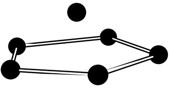
The starting point of deposition dynamics are well relaxed structures for the clusters and pure MgO(001) surface. These had been discussed extensively in Bär et al. (2007). The MgO surface is a cut through cubic crystal structure. From the top, one sees a chess-board structure with alternating Mg and O ions. For the Na clusters, we will use here Na6 and Na8 as examples. The initial state starts from free clusters. Their structures are shown in figure 2. Note that the vertical axis in the figure will represent the direction perpendicular to the surface in the forthcoming deposition processes ( axis). Na6 is strongly oblate consisting out of a ring of five ions topped by one single ion. Na8 has a highly symmetric configuration out of two rings of each four ions tilted relative to each other by 45∘ to minimize Coulomb energy. The electronic cloud of Na8 is close to spherical shape because electrons correspond to a strong shell closure for Na clusters Bjornholm and Borggreen (1999). It is important to note that the bond distances for Na8 (6.2 ) are not far from the diagonal distance between oxygen sites in the MgO(001) surface (5.7 ) while the dimensions of the fivefold ring in Na6 do not fit well to the surface. That will play a role in the dynamical evolution studied later on. The equilibrium distance of the lower cluster plane (facing towards the surface) and the first surface layer is 5 .
III Results and discussion
III.1 Na monomer on MgO – the influence of sites
A two component system like MgO has more possible adsorption sites than a homogeneous material like an argon substrate. The properties of an oxygen site are much different from those of the magnesium site because of the much larger polarizability of oxygen. We will thus consider four positions with respect to the surface : O site, Mg site, hollow and bridge. The structure calculations of Bär et al. (2007) have shown that O, due to its large polarizability, is the most attractive site while Mg acts like a repulsive site on the cluster. This is in agreement with quantum chemical ground state calculations of transition metals on MgO Winkler (2006b).
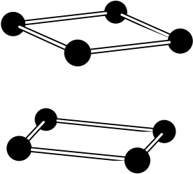
In order to check the adsorption properties of the various sites, we first study the deposition dynamics of a Na monomer. We briefly remind the static properties of Na@MgO(001). The O site is most attractive, binding Na 5 above the surface with energy 0.25 eV. The Mg site is dominantly repulsive. The hollow and bridge sites lie in between these extremes. For deposition dynamics, the atom was initialized 15 away from the substrate above an O site, Mg site or hollow site respectively, each with an initial momentum along direction, pointing perpendicular towards the surface with a magnitude corresponding to a kinetic energy eV. Figure 3 shows the results of the simulation. The -coordinates are chosen such that the (average) MgO surface layer resides at . The simplest case is the impact on the O site. The atom approaches the surface up to a distance of which is reached at about 500 fs and transfers part of its momentum to the substrate ions. The transfer proceeds at a very short time scale. The surface itself is excited mainly by the first collision which initially only affects the ions in the immediate vicinity of the atom at closest impact. The perturbation quickly spreads over the surface, but the associated sound wave does not penetrate very deep into the surface. The oscillations in the third layer are already almost negligible. After the instant of closest contact, the atom bounces back, but it has already lost so much energy that it cannot escape from the surface anymore. Thus it performs damped oscillations, with each bounce transferring some momentum to the surface and being practically adsorbed within the first 2 ps. The final distance approaches nicely the equilibrium distance of 5 . The right upper column of figure 3 shows the corresponding kinetic energy contributions. In the first , the attraction from the MgO substrate leads to a rapid increase of the kinetic energy of the atom up to eV. At the point of closest contact, the repulsive part of the interface potential stops the atom abruptly. That first collision transfers by far the largest amount of energy to MgO, whereas at all subsequent collisions the energy decreases more slowly. In order to check that the oscillations proceed only perpendicular to the surface, the kinetic energy of the Na atom has been split into contributions from perpendicular (or vertical) and parallel (or transverse) motion. The latter is too small to be visible in figure 3 and practically negligible. Thus the motion of Na proceeds strictly perpendicular to the surface. The kinetic energy transferred to the MgO can also be read off from figure 3 (see right upper panel). The contributions from oxygen and magnesium are given separately. Oxygen ions are the lighter species and therefore react first being quickly accelerated. About 100 fs later, the energy has already been distributed almost equally over both ion types.
The dynamics behaves totally different if the atom impinges on the (repulsive) Mg site, see middle panels of figure 3. At first glance, the -component of the Na trajectory looks quite similar to the case before. But one notes that the motion is not damped after the first reflection. The kinetic energies (middle right panel) give a clue on the process. There is much less energy transfer at first impact which is related to the fact that the Mg2+ ion is more inert. And there is a significant amount of lateral kinetic energy for the Na atom creeping up after impact time at 500 fs. In fact, most of the kinetic energy is now in lateral motion. The atom is deflected by the Mg2+ ion. It is to be noted that the annealing of the substrate configuration leaves a small amount of symmetry breaking with fluctuations of the atomic positions of about 0.05 a0. This small symmetry breaking allows the atom to acquire sidewards momentum and so it bounces away in sideward direction, hops over the surface several times changing direction whenever it comes close to another surface ion. The motion is almost undamped because little energy is transferred to the surface after the first collision. The atom has thus still too much energy to be caught by a certain site of the surface. But as the atom cannot escape the surface as a whole, it will continue to lose slowly energy and finally be attached to an oxygen site, long after the simulation time of 3 ps.
The bottom panels of figure 3 show the case of impact at an hollow site. We see again the immediate reflection at impact time associated with fast energy transfer. Less energy is transferred than on the other sites (see upper and middle panels) and thus the bounce-back has a much larger amplitude than in both other cases. The Na motion remains strictly perpendicular to the surface as practically no lateral kinetic energy can be seen. The vertical kinetic energy is almost approaching zero because the departing Na atom has to work against the polarization potential. The case is at the limits of our box size and energy resolution such that we cannot decide whether the atom will finally escape with extremely small kinetic energy, or will bounce back and relax to an adsorption site on a very long time scale. Nevertheless, we find it worthnoting that the hollow site seems sufficiently attractive to hinder deflection towards the still more attractive oxygen site.
III.2 Cluster deposition
III.2.1 The case of symmetric Na8
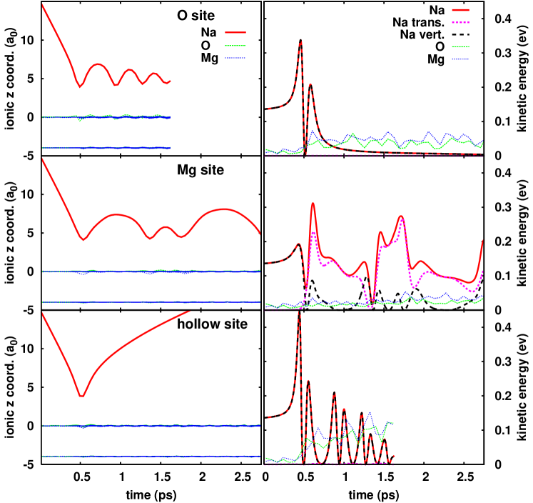
The analysis of section III.1 has shown the importance of surface site nature in the deposition process. Depositing an extended object such as a cluster will lead to a mixed situation because the ions of the cluster will necessarily be placed above different sites. In the following, we will discuss deposition of Na8 and Na6 which have very different structures and so promise to show different deposition scenarios. As a first step in the analysis, we shall consider detailed ionic trajectories both perpendicular and parallel to the surface. The case of Na8 is shown in figure 4. The cluster was injected with its symmetry axis pointing through a hollow site and with the lower ring facing closer to bridge sites. The top panels show a soft deposition where the initial kinetic energy is eV ( eV per Na ion). The left upper panel shows that the cluster is slightly accelerated in the initial phase, due to the attraction from the surface. But that acceleration differs for the different ions on the lower ring because they approach different sites on the surface. At the same time, the cluster rotates in the - plane to bring the four ions of the lower ring closer to the attractive oxygen sites. One may spot that from the top view in the right upper panel. At the point of closest impact around 900 fs, the cluster transfers some momentum to the surface. The substrate ions are slightly displaced from their equilibrium positions and oscillate around their new positions. The disturbance quickly decreases from layer to layer. The perturbation is negligible already in the fourth layer. The complicated detailed dynamics of the Na ions indicates that a major part of the translational kinetic energy is converted into heat, i.e. kinetic energy of the motion relative to the center of mass, as will be confirmed in section III.4. Nevertheless, the cluster basically keeps its original structure during the whole simulation period of 9 ps. In particular the two rings, each made of four ions, always stay clearly separated from each other. The top-down projection of the trajectories (see right-hand side of figure 4) shows that the cluster as a whole (or its center of mass) remains oscillating around the point of impact. The remaining kinetic energy of the cluster does apparently not suffice to overcome the surface corrugation barriers. This is related to the fact that the Na8 structure fits approximately well to the structure and binding distance of MgO, see section II.6.
The middle panels of figure 4 show a more robust deposition dynamics with initial kinetic energy eV. The initial velocity is higher and the impact time comes earlier, now at 450 fs. The pattern remains, in principle, similar to the softer deposition. There is little momentum transfer to the substrate, strong internal excitation of the cluster, and the cluster is not departing too far from the impact point. However, perturbations are much larger, yielding larger amplitudes in vertical and lateral motion. As a consequence, the two rings of Na8 are now not always clearly separated. Nevertheless the typical structure of Na8 reappears from time to time as we will see later. The top-down projection of the trajectories (middle right panel of figure 4) indicates a new effect, a sideward drift from one adsorption site to the next equivalent site. This sideward drift is again induced by the interplay between attractive O and repulsive Mg sites. The chaotically moving Na ions explore a strongly corrugated surface which leads to occasional side kicks from the repulsive Mg sites.
The bottom panels of figure 4 show a hard collision with initial kinetic energy eV. Internal cluster and excitation and surface perturbation are, of course, again larger. The new feature is that the cluster is reflected from the surface and leaves the numerical box at about 1 ps, however with huge internal excitation. It is not clear whether the departing cluster will stay asymptotically stable. That is beyond our simulation capacity.
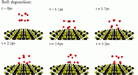
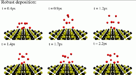
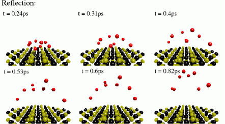
Figure 5 complements the view within showing a sequence of snapshots of the detailed structure for each of the three cases discussed above. The uppermost panel for soft deposition nicely shows the initial rotation of the cluster to match the attractive oxygen sites. The further snapshots indicate the sizeable internal excitation, however remaining small enough to see at all times clearly the two-ring structure of Na8. The middle panel for more robust deposition also presents the much larger cluster oscillations where the original cluster structure is often blurred, but reappears shortly at other times. That demonstrates the surprisingly good binding of Na clusters, particularly the Na8 cluster with its magic electron configuration. The lowest panel shows the case of reflection. Obviously, some ions would like to stick to the surface, but are finally caught back by the cluster which departs in a highly excited state.
III.2.2 The case of strongly oblate Na6
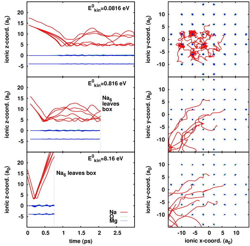
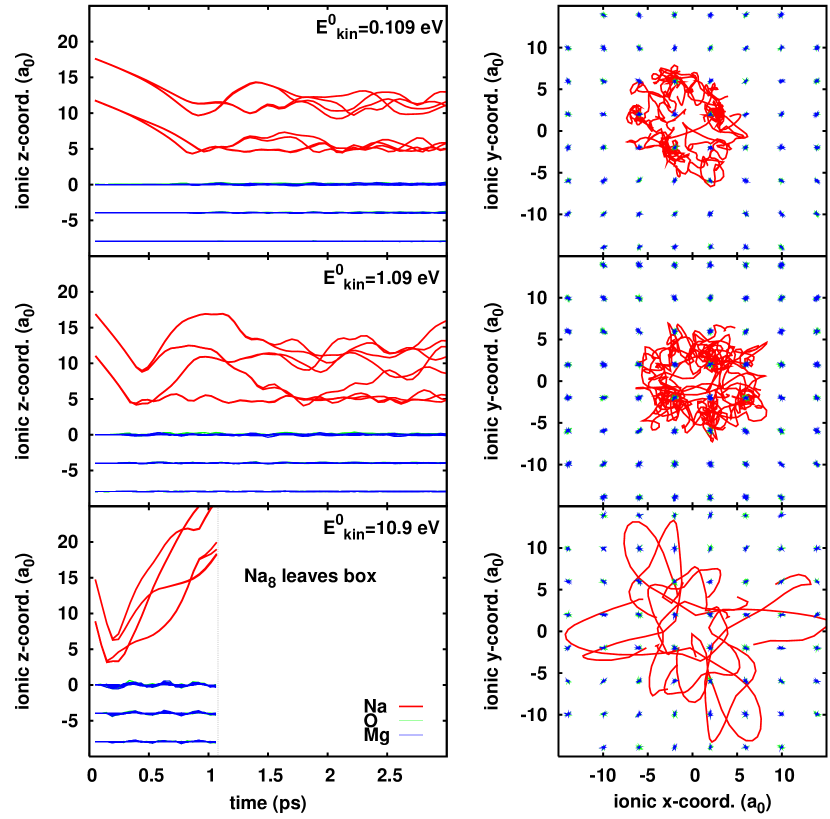
Results for the deposition of Na6 are shown in figure 6. The impact energy is varied and all three cases start from the same initial configuration where the top ion of Na6 (see section II.6) is facing away from the substrate and the fivefold ring is parallel to the surface. The general features are similar to the case of Na8. One observes a large internal excitation of the cluster while comparatively little perturbation goes to the substrate and there is again the clear distinction between deposition for lower impact energies and reflection for higher ones. But there are several interesting differences in detail. Most of all, there is a strong lateral drift in all cases. Indeed the pentagonal ring of Na6 does not match the rectangular structure of MgO, which hinders it from fully accomodating the attractive oxygen sites. Thus one or two corners of the pentagon are bent up during the deposition process, and this, in turn, induces a sizeable lateral momentum (see right panels of figure 6), and a strong perturbation of the pentagon, as can be deduced from the motion of -coordinates shown in the left panels. In the case of the robust deposition, the cluster even rolls over the surface. The stronger lateral excitation leaves also somewhat more perturbation to the substrate than in the case of Na8, as may be spotted when comparing figures 6 and 4. That will become more obvious when checking energies in section III.4. Finally, it is interesting to note that the cluster orientation is also reverted in the case of reflection. The coordinates (upper left panel in figure 6) suggest a process where the ring and the former top ion are reflected ”independently” such that the topping ion is departing ”behind/after” the ring, and thus reverting the cluster orientation.
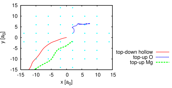
As noted above, when deposited, the Na6 experiences a sizable drift due to the mismatch of its structure with the crystalline structure of MgO. One thus expects that direction and strength of the lateral motion depend sensitively on the initial position and orientation of Na6 relative to the surface. Indeed figure 7 shows the trajectory of the center-of-mass of the Na6 cluster projected onto the --plane for three different initial orientations. There are obvisouly dramatic differences. The cluster is kicked to a strong lateral motion for initial impact at repulsive sites (Mg, hollow) while only moderate lateral drift appears for impact on the attractive O site.
One can learn more about the electronic charge distribution in the cluster during a collision by a direct multipole analysis of this distribution. We discuss here briefly the lowest non-trivial moments, the dipoles.
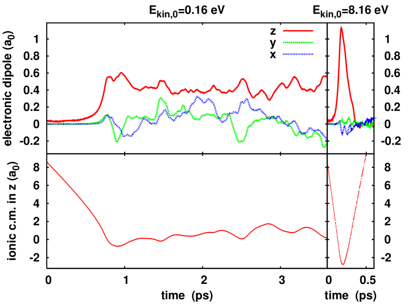
Figure 8 shows the time evolution of dipole polarization for two different scenarios, deposition vs. reflection. The figure is augmented by the time-evolution of the center-of-mass as global indicator of the dynamical situation (lower panels). The two scenarios differ by the initial kinetic energies, the lower value related to a more or less soft deposition, while the higher initial velocity leads to immediate reflection of the cluster, as discussed above. In the slow deposition process (left panels), there is a strong increase of the -polarization at the time of closest impact. This polarization remains during the further evolution at about 10% of the Wigner-Seitz radius, hence represents a considerable internal polarization. Also, some - polarization builds up during the ongoing deposition oscillations. In contrast, in the case of a reflection (right panels), one sees a large instantaneous polarization at the time of closest approach, but only a very small remaining effect when the cluster has departed from the surface. The very short interaction time limits the internal excitation.
III.3 MgO versus Ar Substrate
In previous works Fehrer (2006); Dinh et al. (2007), the deposition of Na6 on a cold, condensed argon substrate Ar(001) was investigated. Like MgO, solid Ar has a large band gap. But apart from this insulating nature, the two materials have much different properties. The attractive interaction between MgO and Na is much stronger than between Ar and Na, due to the larger polarizability of the oxygen ion. On the other hand, frozen Ar material is a very soft solid due to the weak Ar-Ar binding. The melting point of Ar is Ancsin and Phillips (1969), much lower than that of MgO around McDowell and Howe (1920). The softness of the Ar material thus changes the energy balance to the extent that the Ar substrate takes up most of the impinging energy, leaving rather little internal excitation for the cluster itself. Thus Ar substrates are very efficient soft stopper materials. In the former analysis Fehrer (2006); Dinh et al. (2007), we had run a similar series of impact energies as above and we also found soft deposition for energies up to at least eV. An attempt to reach a reflection regime by further increasing the impact energy then led to a significant destruction of the substrate.

Figure 9 illustrates that violent collision of Na6 on an Ar(001) surface. The cluster is indeed finally reflected, but the process evolves much different from the case of the collision with MgO shown in figure 6. The cluster is not reflected instantaneously, as for MgO, but with a delay of about 500 fs. It requires an additional boost from momentum reflected by the first Ar layer to finally release the cluster. Moreover, so much energy has been deposited in the weakly bound Ar material that the substrate is seriously damaged by that forced “reflection”. These significant differences between Ar and MgO substrate will also be seen in the energy analysis later on.
III.4 Energy Transfer
III.4.1 Time evolution of energy components
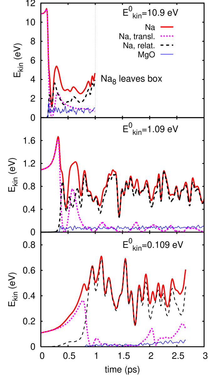
A complementing view of the deposition dynamics is given by the kinetic energies. Figure 10 shows the time evolution of the kinetic energies for Na and MgO. The kinetic energy for the Na cluster is furthermore splitted into center-of-mass energy and intrinsic kinetic energy (from the motion relative to the center-of-mass). Let us first consider the case of reflection (upper panel). In the approaching phase, the cluster is accelerated by about 0.68 eV which is small compared to the initial energy 10.9 eV. Dramatic and fast changes emerge at impact time at 200 fs. The cluster kinetic energy exhibits a deep minimum. In that stage, almost all energy is stored in deformation. A large part of that deformation energy is quickly released showing up now as intrinsic kinetic energy of the cluster plus a smaller bit in translational energy. Another small fraction of energy is transferred to the substrate. The translational kinetic energy decreases further on, because the departing cluster has to work against the attractive polarization interaction. Still, there remains sufficient translational energy to allow the cluster to finally escape, as in a very inelastic collision.
Similar results are found for the soft (lower panel in figure 10) and robust deposition (middle panel). Again, only a small fraction of the energy is transferred to the substrate, another small fraction goes to the cluster center-of-mass oscillations, and the major part to intrinsic energy of the cluster. Particularly interesting is the case of robust deposition (middle panel) where it requires a second bounce to stir up intrinsic cluster motion. Before that, there is still enough energy in translation to allow a lateral hopping from one attractive MgO site to the next (see also figure 4). It is worthnoting that the average trend of the kinetic energy of MgO in figure 10 has a small, but nonvanishing, slope. The cluster continues to exchange energy with the substrate on a very slow pace. That indicates a thermalization process which eventually leads to equidistribution of kinetic energies after long time, however much beyond our simulation capabilities.

The present modeling includes an independent dynamics of the dipole moments of the oxygen anions in the substrate. It has been shown recently that a significant amount of energy can be stored in these degrees-of-freedom when a metal cluster is deposited on an Ar surfaceDinh et al. (2008, 2009). One can define a dipole energy which scales as the square of the dipole amplitudes. Figure 11 shows a typical result for the time evolution of the energy contained in the oscillating dipoles in the case of reflection of Na6 deposited on MgO. There is a small initial value which corresponds well to the finite initial distance of the Na cluster to the substrate. There is a large contribution at the time of closest impact. This part is dominated by (instantaneous) static polarization which would also be contained in a Born-Oppenheimer MD. The dipole energy falls back to lower values when the cluster departs from the substrate (see figure 6). But there remains some offset which corresponds to the energy finally transferred to the dipole degrees of freedom. It amounts to about 2% of the impact energy, which is small compared to the other energetic observables, see figure 14 and corresponding discussion in section III.4.3. In contrast to the case of Ar substrate, energy transfer to MgO dipoles has actually only a small effect for the overall ionic dynamics. But more subtle properties as optical response and trajectories of free charges (to be discussed in a subsequent publication) will be sensitive to such details.
III.4.2 Energy transfers ”at” impact
Notwithstanding asymptotic thermalization, the fast energy transfer to the substrate in the early stages is an interesting observable characterizing the collision process.

Figure 12 shows the kinetic energy of the substrate soon after the collision, i.e. averaged over the first 2 ps after impact, as a function of the initial kinetic energy of the cluster . Apparently the energy absorbed by the substrate is proportional to . But the slope depends very much on cluster and surface types. The soft Ar substrate absorbs much more energy than MgO, typically a bit more than 50% of the initial kinetic energy. The softness and the rather small surface corrugation of Ar make the process insensitive to the actual cluster which is approaching. That is different for MgO. There is always less energy absorption by the substrate and there is a strong dependence on the cluster configuration. Na6 transfers more than twice as much energy as Na8. The strong surface corrugation of MgO induces that sensitivity to cluster geometry. Remind that Na6 does not match very well to the MgO surface while Na8 does (see section II.6).

More information about what is happening directly around impact time can be obtained by reading off observables at shorter time scales (shorter than the 2 ps used above). Figure 13 shows two such observables as a function of initial kinetic energy. The upper panel shows the energy gain in the approaching phase due to the acceleration by the polarization potential. It is defined as the difference of the first maximum of the cluster kinetic energy and the initial energy. Na6 acquires slighlty more energy than Na8 because it has a non-vanishing dipole moment which, in turn, enhances the polarization attraction. There is a large gain in the low energy range (the regime of soft deposit), while the trend becomes very flat for fast collisions. This is probably due to a move from adiabatic to non-adiabatic relaxation processes in the surface. For very low impact velocities, the surface ions have time to follow the forces from the cluster, whereas for very high velocities the surfaces ions do not have enough time to respond before the cluster collides. The lower panel of figure 13 shows an attempt to quantify an “instantaneous energy loss”. To that end, we take difference between the maximum kinetic energy before the impact and the next maximum after the impact. Obviously the instantaneous energy transfer is practically the same for Na6 and Na8 independent of their differences in structure; and the energy loss is approximately proportional to . About half (more precisely around 55%) of the impact energy is withdrawn from the cluster in that first round.
III.4.3 Redistribution of initial kinetic energy
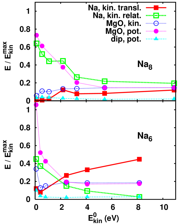
It is, furthermore, interesting to see how the initially available energy is distributed over the various constituents. Such energy balance is shown in figure 14 as a function of . All energies have been averaged over 2 ps after impact time. They are drawn relative to the maximum kinetic energy of the cluster before impact. The energy terms do not necessarily sum up to one because the interaction between substrate and cluster is omitted, as well as the intrinsic potential energy of the cluster. Low energies ( eV for Na8 and eV for Na6) represent the regime of deposition. The largest amount of energy is used up here for intrinsic cluster motion combined with potential energy of the substrate. The latter is responsible for the attachment of the cluster to the surface. The higher energies represent the regime of reflection. The share of energies depends here on the cluster geometry. For Na6, the translational motion takes the lead, whereas the intrinsic motion shrinks to almost zero. That complies with the trajectories in figure 6 which show that the cluster is repelled from the surface with opposite orientation but only weakly perturbed structure. The reflection of the top ion seems to proceed independently from the five-fold ring. The ring hits first and departs first while the top ion is reflected later thus departing behind the ring.
For both clusters, kinetic and potential energies of the MgO behave similar. For high in the reflection regime, potential and kinetic energy are equal. The cluster quickly transfers some momentum to the substrate at impact and then disappears. This leaves the substrate ions oscillating around their equilibrium positions in harmonic motion, associated to equipartition between kinetic and potential energy. For high in the soft landing domain, the situation is different. The potential energy becomes the dominant contribution because the cluster is adsorbed and remains in contact with the surface. This distorts the surface and leads to a large potential energy. Polarization energy is dominating in the potential energy. But the isolated contribution from the oxygen dipoles, also shown in figure 14, is comparatively small. The polarization within the oxygen ions in fact remains small as compared to the polarization caused by the displacement of O versus Mg, each one carrying a net charge of .
IV Conclusions
We have analyzed the dynamics of deposition of small Na clusters on an MgO surface taking up a well tested hierachical QM/MM modeling where the cluster electrons are treated quantum mechanically by time-dependent local-density approximation and the cluster ions as well as the substrate atoms by classical molecular mechanics. The dynamical polarizability of the substrate atoms is taken into account to describe correctly the strong polarization effects in the cluster–material interaction. The results are compared to deposition on Ar surface which is much softer than MgO.
Test cases were Na6, which is a strongly oblate cluster with a finite dipole momentum, and the well bound and highly symmetrical Na8. The general pattern are similar : The clusters are very quickly stopped by the substrate, they transfer a rather small amount of energy to the substrate while acquiring strong internal excitation. For larger impact energies, the clusters are reflected from the surface. This reflection is, of course, inelastic and leaves the clusters departing in highly excited intrinsic motion. There are, on the other hand, significant differences between the two cases, since the cluster geometry has a large influence on the dynamics. The main effects come from the strong surface corrugation of MgO(001). Na6 does not match the surface structure and thus acquires significant lateral motion in contrast to Na8 which keeps better on a vertical track. Moreover, Na6 transfers more energy to the substrate than Na8.
In comparison to Ar(001) surface, we find a similar energy range for deposition and reflection. The details, however, differ dramatically. Deposition on Ar(001) transfers most of the energy to the substrate leaving a rather mildly excited cluster on the surface while there is very little energy transfer to MgO(001) and large intrinsic excitation of the cluster. Reflection from Ar(001) is achieved at the price of severe surface destruction while MgO remains intact at the danger that the highly excited departing cluster may fragment later on.
The detailed energy balance differs in the deposition and reflection regime. In case of deposit, most energy is going to intrinsic cluster excitation and substrate polarization. In case of reflection, there is, of course, more translational energy left for the cluster and the substrate develops equipartition of kinetic and potential energy related to the remaining small, nearly harmonic, oscillations.
Acknowledgements
This work was supported by the Deutsche Forschungsgemeinschaft (RE 322/10-1, RO 293/27-2), Fonds der Chemischen Industrie (Germany), a Bessel-Humboldt prize, and a Gay-Lussac prize.
References
- Meiwes-Broer (2000) K. H. Meiwes-Broer, ed., Metal clusters at surfaces (Springer, Berlin, 2000).
- Binns (2001) C. Binns, Surf. Sci. Rep. 44, 1 (2001).
- Meiwes-Broer (2006) K.-H. Meiwes-Broer, ed., Clusters at Surfaces: Electronic Properties and Magnetism, vol. 82 (2006), Applied Phys. A, special issue.
- Meiwes-Broer and Berndt (2007) K.-H. Meiwes-Broer and R. Berndt, eds., Atomic Clustes at Surfaces and in Thin Films, vol. 45 (2007), Eur. Phys. J. D, topical issue.
- Lambert and Pacchioni (1997) R. M. Lambert and G. Pacchioni, eds., Chemisorption and Reactivity of Supported Clusters and Thin Films, NATO ASI Series E, Vol. 331 (Kluwer, Dordrecht, 1997).
- Watanabe et al. (2006) K. Watanabe, D. Menzel, N. Nilius, and H.-J. Freund, Chem. Rev. 106, 4301 (2006).
- Rösch et al. (2004) N. Rösch, V. A. Nasluzov, K. M. Neyman, G. Pacchioni, and G. N. Vayssilov, in Computational Material Science, edited by J. Leszczynski (Elsevier, Amsterdam, 2004), Theoretical and Computational Chemistry Series, Vol. 15, p. 367.
- Heiz and Landman (2006) U. Heiz and U. Landman, eds., Nanocatalysis (Springer, Berlin, 2006).
- Freund et al. (2000) H.-J. Freund, M. Bäumer, and H. Kuhlenbeck, Adv. in Catalysis 45, 333 (2000).
- Sanchez et al. (1999) A. Sanchez, S. Abbet, U. Heiz, W.-D. Schneider, H. Häkkinen, R. N. Barnett, and U. Landman, J. Phys. Chem. 103, 9573 (1999).
- Diederich et al. (2002) T. Diederich, J. Tiggesbäumker, and K. H. Meiwes-Broer, J. Comp. Phys. 116, 3263 (2002).
- Pinchuk et al. (2004) A. Pinchuk, A. Hilger, G. von Plessen, and U. Kreibig, Nanotechnology 15 (2004).
- Fehrer et al. (2007) F. Fehrer, P. M. Dinh, E. Suraud, and P.-G. Reinhard, Phys. Rev. B 75, 235418 (2007).
- Li et al. (1991) Y. Z. Li, R. Reifenberger, and R. P. Andres, Surf. Sci. 250, 1 (1991).
- Schaefer et al. (1995) D. M. Schaefer, A. Patil, R. P. Andres, and R. Reifenberger, Phys. Rev. B 51, 5322 (1995).
- Kuhrt and Harsdorff (1995) C. Kuhrt and M. Harsdorff, Surf. Sci. 245, 252 (1995).
- Bromann et al. (1996) K. Bromann, C. Félix, H. Brune, W. Harbich, R. Monot, J. Buttet, and K. Kern, Science 274, 956 (1996).
- Fedigro et al. (1998) S. Fedrigo, W. Harbich, and J. Buttet, Phys. Rev. B 58, 7428 (1998).
- Lau et al. (2003) J. T. Lau, W. Wurth, H.-U. Ehrke, and A. Achleitner, Low Temperature Physics 29, 223 (2003).
- Sieber et al. (2006) C. Sieber, W. Harbich, K.-H. Meiwes-Broer, and C. Félix, Chem. Phys. Lett. 433, 32 (2006).
- Duffe et al. (2007) S. Duffe, T. Irawan, M. Bieletzki, T. Richter, B. Sieben, C. Yin, B. V. Issendorff, M. Moseler, and H. H vel, Eur. Phys. J. D 45, 401 (2007).
- Xirouchaki and Palmer (2002) C. Xirouchaki and R. E. Palmer, Vacuum 66, 167 (2002).
- Cheng and Landmann (1993) H. P. Cheng and U. Landmann, Science 260, 1304 (1993).
- Haberland et al. (1993) H. Haberland, Z. Insepov, and M. Moseler, Z. f. Physik D 26, 229 (1993).
- Webb (2007) R. P. Webb, Rad. Eff. Def. Sol. 162, 567 (2007).
- Järvi et al. (2007) T. T. Järvi, A. Kuronen, K. Meinander, K. Nordlund, and K. Albe, Phys. Rev. B 75, 115422 (2007).
- Häkkinen and Manninen (1996a) H. Häkkinen and M. Manninen, Europhys. Lett. 34, 177 (1996a).
- Häkkinen and Manninen (1996b) H. Häkkinen and M. Manninen, J. Chem. Phys. 105, 10565 (1996b).
- Moseler et al. (2002) M. Moseler, H. Häkkinen, and U. Landman, Phys. Rev. Lett. 89, 176103 (2002).
- Ipatov et al. (2003) A. Ipatov, E. Suraud, , and P. G. Reinhard, Int. J. Mol. Sci. 4, 301 (2003).
- Ipatov et al. (2004) A. Ipatov, P.-G. Reinhard, and E. Suraud, Eur. Phys. J. D 30, 65 (2004).
- Inntam et al. (2006) C. Inntam, L. V. Moskaleva, K. M. Neyman, V. A. Nasluzov, and N. Rösch, Appl. Phys. A 82, 181 (2006).
- Dinh et al. (2007) P. M. Dinh, F. Fehrer, P.-G. Reinhard, and E. Suraud, Eur. Phys. J. D 45, 415 (2007).
- Jensen (1999) P. Jensen, Rev. Mod. Phys. 71, 1695 (1999).
- Dinh et al. (2008) P. M. Dinh, F. Fehrer, P.-G. Reinhard, and E. Suraud, Surf. Sci. 602, 2699 (2008).
- Dinh et al. (2009) P. M. Dinh, P.-G. Reinhard, and E. Suraud, Surf. Sci. 603, 400 (2009).
- Bär et al. (2007) M. Bär, L. V. Moskaleva, M. Winkler, P.-G. Reinhard, N. Rösch, and E. Suraud, Eur. Phys. J. D 45, 507 (2007).
- de Heer (1993) W. A. de Heer, Rev. Mod. Phys. 65, 611 (1993).
- Brack (1993) M. Brack, Rev. Mod. Phys. 65, 677 (1993).
- Bjornholm and Borggreen (1999) S. Bjornholm and J. Borggreen, Phil. Mag. 79, 1321 (1999).
- Field et al. (1990) M. J. Field, P. A. Bash, and M. Karplus, J. Comp. Chem. 11, 700 (1990).
- Gao (1996) J. Gao, Acc. Chem. Res. 29, 298 (1996).
- Gresh and Garmer (1996) N. Gresh and D. R. Garmer, J. Comp. Chem. 17, 1481 (1996).
- Mitchell and Fincham (1993) P. J. Mitchell and D. Fincham, J. Phys. Condes. Mat. 5, 1021 (1993).
- Nasluzov et al. (2001) V. A. Nasluzov, K. Neyman, U. Birkenheuer, and N. Rösch, J. Chem. Phys. 115, 8157 (2001).
- Gervais et al. (2004) B. Gervais, E. Giglio, E. Jaquet, A. Ipatov, P.-G. Reinhard, and E. Suraud, J. Chem. Phys. 121, 8466 (2004).
- Fehrer (2006) F. Fehrer, Ph.D. thesis, Universität Erlangen/Nürnberg (2006).
- Fehrer et al. (2005a) F. Fehrer, M. Mundt, P.-G. Reinhard, and E. Suraud, Ann. Phys. (Leipzig) 14, 411 (2005a).
- Calvayrac et al. (2000) F. Calvayrac, P.-G. Reinhard, E. Suraud, and C. A. Ullrich, Phys. Rep. 337, 493 (2000).
- Reinhard and Suraud (2003) P.-G. Reinhard and E. Suraud, Introduction to Cluster Dynamics (Wiley, New York, 2003).
- Dick and Overhauser (1958) B. G. Dick and A. W. Overhauser, Phys. Rev. 112, 90 (1958).
- Legrand et al. (2002) C. Legrand, E. Suraud, and P.-G. Reinhard, J. Phys. B 35, 1115 (2002).
- Winkler (2006a) M. Winkler, Density functional studies of small metal species supported on magnesium oxide, Diploma Thesis, Technische Universität München (2006a).
- Fehrer et al. (2005b) F. Fehrer, P.-G. Reinhard, E. Suraud, E. Giglio, B. Gervais, and A. Ipatov, Appl. Phys. A 82, 151 (2005b).
- Fehrer et al. (2005c) F. Fehrer, P.-G. Reinhard, and E. Suraud, Appl. Phys. A 82, 145 (2005c).
- Blum et al. (1992) V. Blum, G. Lauritsch, J. A. Maruhn, and P.-G. Reinhard, J. Comp. Phys 100, 364 (1992).
- Feit et al. (1982) M. D. Feit, J. A. Fleck, and A. Steiger, J. Comp. Phys. 47, 412 (1982).
- Winkler (2006b) M. Winkler, Diploma Thesis, Technische Universität München (2006b).
- Ancsin and Phillips (1969) J. Ancsin and M. J. Phillips, Metrologia 5, 77 (1969).
- McDowell and Howe (1920) J. S. McDowell and R. M. Howe, J. Am. Ceram. Soc. 3, 185 (1920).