Isotropic magnetometry with simultaneous excitation of orientation and alignment CPT resonances
Abstract
Atomic magnetometers have very high absolute precision and sensitivity to magnetic fields but suffer from a fundamental problem: the vectorial or tensorial interaction of light with atoms leads to ”dead zones”, certain orientations of magnetic field where the magnetometer loses its sensitivity. We demonstrate a simple polarization modulation scheme that simultaneously creates coherent population trapping (CPT) in orientation and alignment, thereby eliminating dead zones. Using 87Rb in a 10 Torr buffer gas cell we measure narrow, high-contrast CPT transparency peaks in all orientations and also show absence of systematic effects associated with non-linear Zeeman splitting.
pacs:
42.50.Gy, 07.55.Ge, 32.10.DkAtomic magnetometers measure the magnetic field by detecting the Zeeman spin precession frequency and can achieve sensitivity surpassing even the best superconducting quantum interference devices (SQUID) Budker and Romalis (2007). They are particularly suitable for operation in Earth’s magnetic field because measurements of the spin precession frequency can be performed with high fractional resolution, are related to the magnetic field only through fundamental constants, and are relatively insensitive to the orientation of the magnetometer. As a result, atomic magnetometers are widely used for the most demanding applications, such as measurements of magnetic fields in space Dougherty et al. (2004); Matousek (2007); Friis-Christensen et al. (2006), mineral exploration Nabighian et al. (2005), searches for archeological artifacts David et al. (2004), and unexploded ordnance Nelson et al. (2005).
Since their inception, all types of atomic magnetometers have suffered from a fundamental problem known as a ”dead zone” Bloom (1962): for certain orientation of the magnetic field relative to the device the magnetometer signal goes to zero. Dead zones are an inherent feature of the vector or tensor interactions used for optical pumping and detection of spin oscillations: for certain orientations the interaction term goes to zero. Previous solutions to this problem included using multiple magnetometer cells or beams Cheron et al. (1997); Chéron et al. (2001), mechanical rotation of some componentsGuttin et al. (1994), and use of unpolarized light and spatially-varying microwave fields Aleksandrov et al. (2006). Particularly for space magnetometers it presents a serious challenge that requires increased complexity of the system Matousek (2007); Friis-Christensen et al. (2006).
Here we demonstrate a dead-zone-free Rb magnetometer utilizing a single interaction region. The magnetometer uses a single laser beam with polarization modulation at the Zeeman frequency to simultaneously excite and detect the precession of the dipole and quadrupole (alignment and orientation) moments of the atomic density matrix. Because the vector nature of the two interactions is different, the transmission of the laser beam is sensitive to the magnetic field for all orientations.
Excitation of magnetic resonances using light intensity modulation was first demonstrated by Bell and Bloom Bell and Bloom (1957) and polarization modulation was explored in Gilles et al. (1991); Klepel and Suter (1992). Magnetometery based on precession of alignment was extensively explored in non-linear magneto-optical rotation (NMOR) magnetometers Budker et al. (2002) while transmission monitoring has been used in CPT magnetometers Nagel et al. (1998); Stahler et al. (2001); Schwindt et al. (2004). However, in all these cases the magnetometer signals go to zero for certain orientations of the magnetic field. We show that with a particular choice of light modulation parameters and the detection method one can realize a CPT magnetometer operating simultaneously on two different coherences without any active adjustments, resulting in a large response for all orientations of the magnetic field.
In addition to avoiding dead zones our arrangement also largely eliminates ”heading errors”, another long-standing problem, particulary for alkali-metal magnetometers. Heading errors are due to non-linear Zeeman splitting of the magnetic sublevels given by the Breit-Rabi formula. By using symmetric optical pumping with equal intensities of and light we eliminate spin polarization along the magnetic field. The remaining third-order heading error Seltzer et al. (2007) is suppressed by the square of the ratio of the Zeeman frequency to the hyperfine frequency. The error due to nuclear magnetic moment is also avoided by optical pumping on only one of the hyperfine ground states.
Consider light polarized linearly in the direction with intensity propagating parallel to the axis, passing through a polarization modulator with an optic axis at 45∘ to and a retardation angle . The following Stokes parameters of the light will be modulated
| (1) | |||||
| (2) |
The interaction of light with atoms can be written as an effective non-hermitian ground-state Hamiltonian Happer (1972)
| (3) |
where and are the electric field and electric dipole operator, is the laser frequency, is the transition frequency from the ground state to the excited state , and is the excited state decay rate. The Hamiltonian can be decomposed into a sum of scalar, vector and tensor componentsHapper (1972); Geremia et al. (2006). Retaining only terms proportional to the modulated Stokes parameters we obtain
| (4) |
where , are the vector and tensor atomic polarizability constants respectively, defined in Geremia et al. (2006). Light absorption in the vapor and the de-population optical pumping rate are both proportional to the non-hermition part of the Hamiltonian Happer and Mathur (1967); Mathur et al. (1970); Happer (1972). In particular, for weak light intensity the atoms will develop orientation and alignment due to depopulation optical pumping. The effects of repopulation optical pumping are relatively small in the presence of buffer gas due to fast excited state spin relaxation.
The modulation of the Stokes parameters can be expanded in terms of Bessel functions:
| (5) | |||||
| (6) |
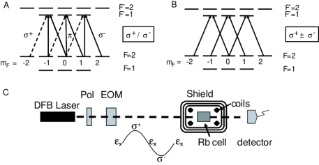
One can see that for small we get modulation of at and modulation of at . The Bell-Bloom (BB) magnetometer Bell and Bloom (1957) (Fig. 1A) relies on the Larmor precession of the atomic orientation If the frequency of the modulation matches the Larmor precession frequency , then will be synchronously excited due to depopulation pumping by the modulation of The average transmission of the light through the cell will be increased due to the term . However, when the magnetic field is parallel to the axis, does not precess and the Bell-Bloom magnetometer has a dead zone for parallel to the light direction. For this case, however, one can see that the alignment will precess at (Fig. 1B). Hence it can be synchronously excited by modulation in when and the transmission through the cell will increase due to the term. Thus, average transmission through the cell will exhibit a CPT transmission resonance at the same frequency for all orientations of the magnetic field.
The experimental apparatus and the atomic levels diagrams are presented in Fig. 1. A 795 nm DFB (Distributed Feedback) diode laser is used for excitation and detection of the D1 transition in 87Rb. A linear polarizer and an Electro-Optic Modulator (EOM) with its principle axes at degrees relative to the input polarization are used for generating the time dependent polarization modulation seen in Fig. 1. The modulated light is sent through a cm3 glass cell with isotopically enriched 87Rb metal and 10 Torr of N2 buffer gas. The walls of the cell are coated with OTS coating and allow about 800 bounces before spin relaxation Seltzer and Romalis (2009). The cell is heated to C and located inside 3 layers of metal shielding, achieving magnetic field screening of orders of magnitude. A set of coils insides the shields is used for applying the needed magnetic fields in any orientation. Another set of coils was used for nullifying residual magnetic field gradients. The transmitted light intensity through the cell is measured with a photo-detector.
The wavelength dependance of the vector and tensor interactions for 87Rb vapor in the presence of buffer gas and Doppler broadening has been considered in Mathur et al. (1970). The imaginary part of is maximized for both vector and tensor components close to the D1 transition. The maximum of the scalar absorption also occurs near the same frequency, hence the laser frequency can be locked to the transmission minimum using laser frequency modulation.
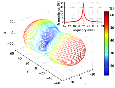
The applied voltage on the EOM was set to oscillate sinusoidally with a retardation amplitude of approximately and the modulation frequency was scanned around the Larmor frequency . In order to check the response of the magnetometer to magnetic fields in any orientation, superposition of electrical currents was injected to the three axes of the Helmholtz coils inside the shields. An example of the measured transparency peak is shown in the inset of Fig. 2. The applied magnetic field was 28.6 mG, which corresponds to a Larmor frequency of 20 kHz. The contrast in this case is 50 and the FWHM of the CPT transmission resonance is 350 Hz. The measured contrast detected from each trace, for equally spread 58 orientations, was used for constructing the 3D plot in Fig. 2. Cubic spline interpolation was used for obtaining clearer 3D view of the measured results. As shown in the 3D plot, there are no dead zones. One can also see that the measured contrast along the three major axes is different.
The natural axes of our scheme are set by the light propagation direction, , the orientation of the linear polarization, and the magnetic field. In the case of field parallel to the propagation vector, the linear polarization component of the light modulated at 2 generates CPT between appropriate Zeeman sub-levels () (Fig. 1B). Destructive interference of the transition amplitudes in this system will induce a transparency peak at resonance Nagel et al. (1998). The BB signal is zero for this orientation. For a magnetic field oriented in a plane perpendicular to the propagation vector (, ), the circular polarization components ( or ) modulated at the Larmor frequency () will induce a BB transparency peak at the Zeeman resonance (, Fig. 1A). With the quantization axis in the transverse plane the circularly polarized light can be thought of as “” polarization and “” polarization generating a transparency peak resonance at . This orientation term will give a symmetric contribution to the transparency along and axes. In addition, the CPT resonance at 2 (alignment term) will also contribute to the signal in this plane. One can see from Eq. (4) that there are two dead zones in CPT resonance for magnetic field in directions, as expected for a rank-2 tensor. For B field at to , the signal is entirely due to BB resonance. When both CPT and BB signals are present, their interaction is complicated by the fact that large spin orientation created by BB modulation also leads to a significant alignment. The sign of this contribution to the second term in Eq. (4) is opposite for magnetic field in and directions. As a result, CPT and BB resonances add constructively for and destructively for . By choosing an appropriate modulation depth and laser power one can adjust the relative strength of the two signals and make the ratio of maximum to minimum contrast to be approximately 3:1 while maximizing the overall contrast. Experimentally we find the measured contrast ranges between 15-60 while the FWHM is 350-700Hz, without any dead zones, as seen in Fig. 2.
In Fig. 3 detailed contrast measurements along the three major planes are shown. The upper set corresponds to the signal with both CPT and BB signals, with parameters similar to data in Fig. 2. The lower set is a reference measurement where the CPT contribution to the signal is eliminated by choosing a specific laser detuning to the midpoint between upper levels where the constructive interference of the CPT signal is exactly cancelled due to different phase contribution of the two upper levels. It is evident from the figure that no signal is measured along the axis in the BB scheme whereas this ”dead zone” is totaly avoided in the new scheme. Moreover, along one axis (), the signal’s strength is much larger and narrower than common BB magnetometers’ signal, demonstrating a better signal to noise ratio.
The fast and balanced alternation between right and left circular polarization at the Larmor frequency also eliminates the problem with heading errors. Heading error induced by an asymmetric illumination of the atoms is manifested at magnetic fields on the order of the Earth’s magnetic field (0.5Gauss) due to the non-linear terms in the Breit-Rabi formula. In order to check this issue, we used the same experimental setup at a higher magnetic field. The EOM was driven at 1.9-2.2 MHz, corresponding to about 3 Gauss for 87Rb atoms. By working at a field which is 6 times the Earth’s magnetic field any distortion in the transparency due to the quadratic nature of the Breit-Rabi splitting should be observed.
The measured signal in Fig. 4 corresponds to a case where a 2.85 Gauss magnetic field is tilted toward the Z axis by 26.5∘ from either the or axis. This compares signals with the largest possible contrast difference, corresponding to the sum and the difference of the BB and CPT contributions. Whereas at low fields a single narrow peak is observed (e.g. Fig. 2), in this large field regime the Zeeman resonance is split into multiple peaks, particularly pronounced in the X-Z plane. The crucial observation here is that the signals are centered and symmetric. Therefore, changes between the strength of BB and CPT contributions associated with rotation of the magnetometer in an external field will not result in a shift of the central frequency.
In Fig. 4 we also present a case where unbalanced contribution in the modulated light field is obtained by inducing an additional bias to the EOM’s driving voltage. In this case the asymmetric signal will induce a heading error. This error is avoided in the current scheme due to the symmetric contribution of the various polarization components. In practice, one would also have to minimize residual polarization bias from stress-induced birefrigence in various optical elements to obtain good suppression of heading errors.
In summary, a fundamental problem of “dead zones” in atomic magnetometers caused by the vectorial or tensorial interaction with the light has been resolved by a simple polarization modulation scheme. Such technique can be applied to both alkali-metal and metastable 4He magnetometers. We expect that the sensitivity of such magnetometer can reach picotesla level since measured CPT contrast ratio and linewidth are similar or better than in previous CPT magnetometers Stahler et al. (2001); Schwindt et al. (2004). In the simplest implementation of the magnetometer, frequency modulation at a few hundred hertz of the voltage applied to the EOM can be used to lock to the maximum of the average transmission through the cell. It is also possible to further improve the performance of the magnetometer by measuring the phase of the second and fourth harmonics of the Larmor frequency in the transmission signal, analyzing the polarization of the transmitted light or using a separate probe laser. The amplitude of the EOM excitation can also be continuously adjusted to maximize the signal for any given orientation of the magnetic field.
The heading errors specific to alkali-metal magnetometers in geomagnetic field are also largely eliminated due to symmetric optical pumping. Thus we expect that this technique will enable high precision isotropic magnetometry in many Earth-bound and space applications. Moreover, controlled excitation of orientation and alignment by polarization modulation of light can be used for better control of the atomic density matrix in various atomic physics experiments.
We would like to thank Vishal Shah for assistance with the measurements and Tom Kornack and Scott Seltzer for fabricating the cell. This work was supported by an ONR MURI award.
References
- Budker and Romalis (2007) D. Budker and M. Romalis, Nature Phys. 3, 227 (2007).
- Dougherty et al. (2004) M. Dougherty et al., Space Science Rev. 114, 331 (2004).
- Matousek (2007) S. Matousek, Acta Astronautica 61, 932 (2007).
- Friis-Christensen et al. (2006) E. Friis-Christensen, H. Lühr, and G. Hulot, Earth Planets Space 58, 351 (2006).
- Nabighian et al. (2005) M. Nabighian et al., Geophysics 70, 33ND (2005).
- David et al. (2004) A. David et al., Antiquity 78, 341 (2004).
- Nelson et al. (2005) H. Nelson, J. McDonald, and D. Wright, Tech. Rep. NRL/MR/6110–05-8874, NRL (2005).
- Bloom (1962) A. L. Bloom, Appl. Opt. 1, 61 (1962).
- Cheron et al. (1997) B. Cheron et al., J. Phys. III France 7, 1735 (1997).
- Chéron et al. (2001) B. Chéron, H. Gilles, and J. Hamel, Eur. Phys. J. AP 13, 143 (2001).
- Guttin et al. (1994) C. Guttin, J. Leger, and F. Stoeckel, J. Phys. IV Collocq France 55, C4 665 (1994).
- Aleksandrov et al. (2006) E. B. Aleksandrov, A. K. Vershovskii, and A. S. Pazgalev, Technical Physics 51, 919 (2006).
- Bell and Bloom (1957) W. E. Bell and A. L. Bloom, Phys. Rev. 107, 1559 (1957).
- Gilles et al. (1991) H. Gilles, J. Cheron, and J. Hamel, Opt. Comm 61, 369 (1991).
- Klepel and Suter (1992) H. Klepel and D. Suter, Opt. Comm. 90, 46 (1992).
- Budker et al. (2002) D. Budker et al., Rev. Mod. Phys. 74, 1153 (2002).
- Nagel et al. (1998) A. Nagel et al., Europhys. Lett. 44, 31 (1998).
- Stahler et al. (2001) M. Stahler et al., Europhys. Lett. 54, 323 (2001).
- Schwindt et al. (2004) P. D. Schwindt et al., Appl. Phys. Lett. 85, 6409 (2004).
- Seltzer et al. (2007) S. J. Seltzer, P. J. Meares, and M. V. Romalis, Phys. Rev. A 75, 051407(R) (2007).
- Happer (1972) W. Happer, Rev. Mod. Phys. 44, 169 (1972).
- Geremia et al. (2006) J. M. Geremia, J. K. Stockton, and H. Mabuchi, Phys. Rev. A 73, 042112 (2006).
- Happer and Mathur (1967) W. Happer and B. S. Mathur, Phys. Rev. 163, 12 (1967).
- Mathur et al. (1970) B. S. Mathur, H. Y. Tang, and W. Happer, Phys. Rev. A 2, 648 (1970).
- Seltzer and Romalis (2009) S. J. Seltzer and M. V. Romalis, J. Appl. Phys. 106, 114905 (2009).