Thermal Control of a Dual Mode
Parametric Sapphire Transducer
Abstract
We propose a method to control the thermal stability of a sapphire dielectric transducer made with two dielectric disks separated by a thin gap and resonating in the whispering gallery (WG) modes of the electromagnetic field. The simultaneous measurement of the frequencies of both a WGH mode and a WGE mode allows one to discriminate the frequency shifts due to gap variations from those due to temperature instability. A simple model, valid in quasi equilibrium conditions, describes the frequency shift of the two modes in terms of four tuning parameters. A procedure for the direct measurement of them is presented.
1 Introduction
Adielectric whispering gallery resonator, made with two dielectric disks separated by a thin gap is a very sensitive displacement sensor [1]. Indeed, parametric microwave sapphire oscillators, operating at cryogenic temperature, have been proposed as readout systems for bar-type gravitational antennae [2] and also as core sensors for space-gravity tests and geodesy research [3]. It has been shown that such devices provide high sensitive vibration measurements even when operating at room-temperature [4].
The efficiency of these transducers is conveniently described by the merit factor
where is the resonator quality factor, its resonance frequency and is the tuning coefficient, the derivative of the resonance frequency w.r.t. the gap spacing .
The modes are classified as modes (characterized by and modes (with , where denotes the component of the field vector along the disks rotational axis, the radial component, and the azimuthal one.
The modes with high azimuthal mode number present the highest merit factors [2].
Even at room temperature, X-band resonances in a sapphire resonator made with disks 4 cm in diameter and 0.5 cm in thickness, exhibit a factor of and a tuning coefficient of so that . The frequency instability is dominated by thermal effects, which contribute with some tenths of .
This strong temperature dependence of the dielectric tensor compromises the long term stability. On the other side, ultra-low frequency (i.e. diurnal timescale) displacement measurements have a key role in many applications such as gravimetric exploration, environmental monitoring and materials testing.
In the research field of ultra stable oscillators, several techniques for precision temperature stabilization have been proposed.
At low temperature (below 100 K) the cancellation (to first order) of the temperature coefficient of frequency can be achieved by employing doped dielectric disks [5], composite sapphire-rutile resonators [6] and mechanically compensated structures [7].
High thermal stability at room temperature can be obtained with high precision control stages, by the optimization of temperature sensors [8] and actuators [9], and also by accurately modelling and simulating the thermodynamic system under test [10].
Due to the anisotropy of the sapphire crystal, the temperature coefficient of frequency is in general different for WGH and WGE modes. Exciting two electromagnetic modes with different polarization in the same resonator permit one to measure and stabilize the resonator temperature in oscillators [11, 12] even at room temperature [13]. In the case of a displacement transducer, WGH and WGE modes have to satisfy different boundary conditions at the gap spacing thus exhibiting also different tuning coefficients .
The measured resonance frequency variations in a parametric sapphire transducer are given by the mixing of pure-displacement signals, pure-temperature signals and temperature-induced displacement signals. These last are due to the thermal expansion of the material comprising the enclosing chamber.
In this paper we propose a calibration technique providing an estimate of pure displacement signals in a dual mode parametric sapphire resonator transducer operating at room temperature.
2 Thermal effects in a Sapphire Parametric Transducer
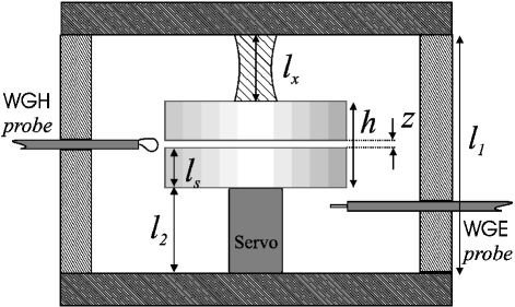
The frequency dependence on temperature for the parametric displacement transducer of Fig. 1 is described by the following equation [12]:
| (1) | |||
where are coefficients depending on the materials and are the filling factors of the considered WG mode and depend on the field distribution of the mode inside the resonating volume. The label refers respectively to: and the dielectric constants perpendicular and parallel to the c-axis, and the resonator spatial dimensions perpendicular and parallel to the c-axis, , , , , the vertical dimensions of the single sapphire disk, the chamber length, the lower support (actuator), the upper support (moving part) and the gap spacing. Under stationary conditions, one can assume to be valid the following linear and time-independent relation between a given pair of WG modes, the temperature and the gap spacing :
| (2) |
with
| (3) |
The anisotropy of both the material and the field distribution assures that it is possible to invert C and to obtain the following estimate for the effective temperature fluctuations and for the pure (not thermally-induced) displacement :
| (4) |
3 Calibration
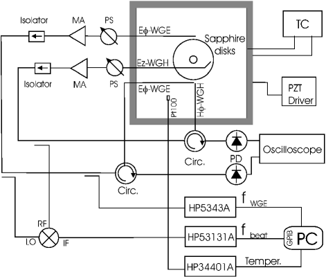
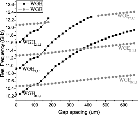
The basis of the method is to determine the coefficients of the matrix C by means of a calibration procedure. A schematics of the experimental apparatus for the sensor calibration is shown in Fig. 2. The sapphire transducer is placed inside a metallic chamber which is temperature stabilized at about . Each chamber wall is electrically isolated in order to avoid any influence from cavity modes on the chosen WG modes in the dielectric. A 4 cm thick insulation material covers the whole chamber to reduce the heat losses. The temperature stabilization system consists of a standard PI controller driving a set of thermoresistances in thermal contact with the metallic cavity. The set point temperature is determined by a voltage input for calibration purposes. The sapphire disks composing the resonator transducer are coupled to four microwaves antennae (see Fig. 2). Two electric probes, coupled to the azimuthal electric field are used for sustaining the WGE oscillations. One electric probe, coupled to the axial electric field, and one magnetic probe, coupled to the azimuthal magnetic field, excite the WGH oscillations. We chose to test the system using the following modes (see Fig. 3):
| (5) | |||||
for . In this choice there is very little coupling [1] between the selected modes and furthermore they are close enough in frequency so that it is possible to measure their beat note by means of an RF frequency counter. The upper resonator disk is rigidly attached to the aluminium top plate and the lower disk is mounted on a piezoelectric actuator.
A PC based data acquisition system monitors three physical quantities: internal temperature (via the resistance of a Pt100 temperature probe), the mode frequency (with a microwave frequency counter) and the beat frequency (with an RF frequency counter).
4 Check of the method
Once the two microwave oscillations are implemented, we can evaluate the four elements of the C matrix by means of the temperature and position controllers. and are given by the ratio between the frequency variation of and and the calibrated gap variation induced by the piezoelectric actuator moving the lower disk.
and are instead the proportionality constants between the frequency variation extrapolated at thermal equilibrium and the temperature variation induced by thermal actuators. For the present setup we obtained:
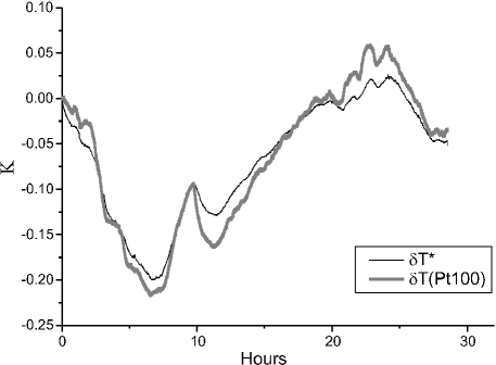
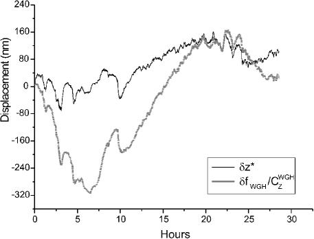
In Fig. 4 we show a comparison between the frequency-based temperature variation estimate and the temperature variation measured by a Pt100 thermometer placed inside the chamber. The measurement is referred to stabilized temperature conditions and rigid materials. The agreement between the two traces confirms the validity of the model especially for very slow variations and makes it possible to measure the sensor temperature sensitivity by means of frequency measurements. In Fig. 5 we show a comparison between the displacement estimate , obtained from the calibrated dual frequency measurement, and i.e. the displacement estimate one would get from the mode alone (the most sensitive mode to the gap spacing variation). It is neatly visible that the trace displays a net reduction of the fluctuations over time scales typical of thermal phenomena.
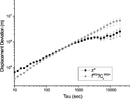
It is worth remarking that the assumption of thermal equilibrium for the system is essential to effectively filter out the temperature noise from the displacement signal. In Fig. 6 we show the Allan deviation (where is the average of the displacement over the i–th sample–period of duration ) of the two displacement traces of Fig. 5.
It can be seen that for integration times below about 200 sec the dual mode based displacement measurements are noisier than the single frequency measurements. This is due to the fact that over these time scales the different sensor components are not in thermal equilibrium and the two frequencies are almost uncorrelated. For integration times above about 500 sec, a net reduction of noise can be observed for the trace due to . This time scale corresponds to the longest time constant (sapphire thermalization) in the sensor. Here thermal equilibrium approximation is almost valid and then the method provides the expected noise cancellation.
5 Conclusions
We proposed and tested an experimental technique for reducing the instabilities induced by thermal fluctuations in a sapphire parametric displacement transducer. The effective temperature of the sensor and the pure displacement signal can be obtained from a double frequency measurement. The very simple time-independent model of the system has been tested on a trial setup in order to outline the potential and the limitations of the method. In the future we intend to improve the efficiency of the thermal stabilization and isolation of the system in order to improve the bandwidth of the noise filtering. Finally by implementing a double locking of the two reconstructed quantities ( and ) it will be possible to implement the experiment under static conditions and improve on the modelled assumptions.
References
- [1] D.G. Blair, E.N. Ivanov and H. Peng “Sapphire dielectric resonator transducers,” J. Phys. D: Appl. Phys., vol. 25, pages 1110-1115, 1992.
- [2] D.G. Blair, E.N. Ivanov, M.E. Tobar and B.D. Cuthbertson, “Sensitivity and optimization of a high-Q sapphire dielectric motion-sensing transducer,” IEEE Trans. Ultrason. Ferroelect. Freq. Contr., vol. 45, pages 1303-1313, 1998.
- [3] L.P. Martin, J.J. Suter and M. Rosen, “Sapphire resonator transducer accelerometer for space gravity gradiometry,” J. Phys. D: Appl. Phys., vol. 27, pages 875-880, 1994.
- [4] D.G. Blair, E.N. Ivanov and H. Peng, “An ultrahigh sensitivity sapphire transducer for vibration measurements,” J. Phys. D: Appl. Phys., vol. 27, pages 1150-1155, 1994.
- [5] J. G. Hartnett, M. E. Tobar, A. G. Mann, E. N. Ivanov, J. Krupka, and R. Geyer, “Frequency-temperature compensation in and doped sapphire whispering gallery mode resonators,” IEEE Trans. Ultrason. Ferroelectr. Freq. Control, vol. 46 (4), pages 993 1000, 1999.
- [6] J.G. Hartnett, P.Y. Bourgeois, J.D. Anstie, M.E. Tobar, N. Bazin, E.N. Ivanov, D. Cros, V. Giordano, Y. Kersale, “High-Q frequency-temperature compensated solid-nitrogen-cooled resonator-oscillators: first results,” Electronics letters, vol. 40, pages 41-42, 2004.
- [7] G. J. Dick, D. Santiago and R. T. Wang, “Temperature-Compensated Sapphire Resonator for Ultra-Stable Oscillator Capability at Temperatures Above 77 K,” IEEE Trans. Ultrason. Ferroelectr. Freq. Control 42 (5), 1995.
- [8] Y. Kersale, F. Lardet-Vieudrin, M. Chaubet, and V. Giordano, “ Thermal stabilisation of high-Q sapphire microwave resonator using thermosensitive quartz sensor,” Electronics letters, vol. 34 (8), pages 783-784, 1998.
- [9] M. E. Tobar, A. J. Giles, S. Edwards, and J. H. Searls, “Low Noise 9-GHz Sapphire Resonator- Oscillator with Thermoelectric Temperature Stabilization at 300 Kelvin,” IEEE Trans. Ultrason. Ferroelectr. Freq. Control, vol. 5 (4), pages 108-110, 1995.
- [10] R. Boudot, C. Rocher, N. Bazin, S. Galliou, and V. Giordano, “High-precision temperature stabilization for sapphire resonators in microwave oscillators,” Rev. Sci. Instr., vol. 76, 095110, 2005.
- [11] M. E. Tobar, E. N. Ivanov, C. R. Locke and J. G. Hartnett, “New method to build a high stability oscillator from the temperature compensation of the different frequency between modes of orthogonal polarization,” IEEE Trans. Ultrason. Ferroelectr. Freq. Control, vol. 50, pages 214-219, 2003.
- [12] M. E. Tobar, G. L. Hamilton, J. G. Hartnett, E. N. Ivanov, D. Cros and P. Guillon, “The dual-mode frequency locked technique for the characterization of the temperature coefficient of permittivity of anisotropic materials,” Meas. Sci. Technol., vol. 15, pages 29-34, 2004.
- [13] J.A. Torrealba, M.E. Tobar, E.N. Ivanov, C.R. Locke, J-M. Le Floch, D. Cros, and J.G. Hartnett, “Room Temperature Dual-Mode Oscillator- First Results,” Electronics letters, vol. 42 (2), pages 99-100, 2006.