Electrically Tunable Dicke Effect in Double-Ring Resonator
Abstract
The Dicke effect is examined in an all-optical system of an optical waveguide side coupled to two interacting ring resonators in a liquid crytal environment. The system is shown to exhibit all the signatures of the Dicke effect under an active and reversible control by an applied voltage.
pacs:
42.60.Da, 42.50.Nn, 42.79.GnSubstantial narrowing of the spectral line shapes due to collisions of radiating and non-radiating atoms is first described by R. H. Dicke in 1953 and called as the Dicke Effect Dicke (1953). The overall line shape consists of a superposition of a broad and a narrow line shapes centered at the transition frequency. Such a splitting of atomic decay into a pair of fast and slow decay channels is closely related to the superradiance phenomenon predicted shortly after the Dicke effect Dicke (1954). Superradiance is cooperative spontaneous emission of radiation from an initially excited coherent ensemble of atoms. The slow and fast decay channels are respectively named as subradiant and superradiant decays of the system. Collective symmetric or anti-symmetric states of an ensemble of atoms are respectively in superradiant or subradiant phases.
In addition to the atomic ensembles, The Dicke effect has been extensively studied in other systems, such as photonic crystals H bner et al. (1996), plasmonic lattices Christ et al. (2007), electronic mesoscopic systems, Brandes (2005); Apel et al. (2008); Orellana et al. (2006, 2004); Podivilov and Shapiro (1992); Vorrath and Brandes (2003); Brandes and Kramer (1999); Shahbazyan and Raikh (1994) and in electron waveguides Lee and Reichl (2008, 2009). Not all the signatures of the Dicke effect can be found in many of these systems. Furthermore, control of the Dicke effect is too challenging. Our purpose is to examine the Dicke effect in an all-optical device with active and reversible control. We find that a pair of microring resonators coupled to a waveguide can exhibit all the key signatures of the Dicke effect in a controllable way with the help of a nematic liquid crystal (NLC). Tunable lifetimes of quasibound states in the resonators can be translated into reversible active control of optical signals in multiple ring resonator configurations. Such systems are used for many optical communication and signal processing applications such as all-optical logic gates Blom et al. (1997) and all-optical memory elements Hill et al. (2004).
From a fundamental perspective, the system allows for controlled investigations of quantum interference and decoherence by providing an all-optical analog of an Anderson-Fano model which is the prototype description of interaction between (quasi) bound and (quasi) continuum states Anderson (1961); Fano (1961). In addition, extending the system to multiple ring configuration, quantum phase transitions in the context of superradiance can be systematically examined and probed (For a review see Brandes (2005) and references therein).
It has been shown that NLC can be used to tune the resonances of a single ring resonator coupled to a waveguide Maune et al. (2003). To control linewidths, we introduce another ring to that system as depicted in Fig. 1, where two identical microring resonators at a distance apart are side coupled to a waveguide. A TE polarized Gaussian beam (electric field is perpendicular to the plane of the resonators) is sent from the input port of the waveguide. Two electrodes provide a voltage to change orientation of the NLC molecules used for cladding the resonators. Similar set up but without NLC has been examined for its reflective properties Chremmos and Uzunoglu (2005); Chung et al. (2006). NLC allows for controllable coupling coefficients between the resonators and the waveguide.
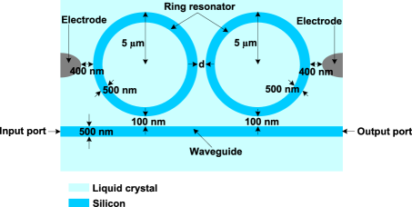
For a single ring, the resonance wavelength is determined by the Fabry-Perot etalon resonance condition, where , is the wavelength of the mth resonator mode, is the radius of the microring and is the effective refractive index for the waveguide mode Maune et al. (2003); Saleh and Teich (1991). Proximity coupling by the evanescent tails makes depending on the refractive index of the NLC cladding, which is determined by
| (1) |
where and at nm Maune et al. (2003), and is the angle of the NLC directors (a local pseudo vector in the mean molecular long axis direction) relative to the radial axis from the origin in the middle of the electrodes Maune et al. (2003); Dunmar and Toniyama (Wiley-VCH, New York, 1998).
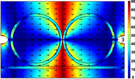
When there is no applied field, assuming the optical field is too weak to induce any reorientation (optical Frederick’s effect) of the NLC directors, the NLC is in the isotropic phase, so that . When sufficiently strong potential is applied from the electrodes, the directors are deformed as shown in Fig. 2. is locally determined by the Euler-Lagrange equations, to minimize the free energy density of the NLC with given elastic properties. For a potential field much stronger than the elastic contribution, the directors will be fully polarized in the applied electric field direction Collings (2002). This permits local modulation of the , analogous to electrooptic effect. The electric field lines in Fig. 2, which is numerically determined by the Poisson equation, indicate the director alignments that can be controlled by the boundary conditions at the electrodes Maune et al. (2003). After distribution is found, spatially inhomogeneous refractive index of NLC cladding is calculated by Eq. 1, which is used to propagate the Gaussian beam in the waveguide and to evaluate its transmission. We have repeated this process for different potential values and different separations between the rings.
Using transfer matrix formalism Poon et al. (2004a, b), reflection characteristics of coupled ring resonators have been examined Chremmos and Uzunoglu (2005); Chung et al. (2006). In order to examine the coupling between the electromagnetic modes as realistically as possible, and to treat NLC cladding correctly, we follow a computational approach based upon finite element methods num . We verify that our numerical analysis yields the similar lineshape structures obtained by the transfer matrix method. We calculate the resonances by evaluating the intensity of the wave at the output port of the waveguide, . The spatially inhomogeneous is used in the coupled wave equations to solve for the resonator and the waveguide modes and the evanescent waves in the NLC. Different computational grids are used for every different geometry arising when the ring separation is varied.
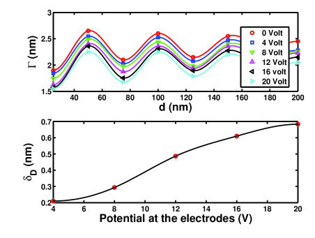
The resonances of the system for different values without an applied potential are shown in Fig. 3. Characteristic splitting of the single ring resonance into four peaks is observed. Four peaks arise due to simultaneous presence of direct proximity coupling together with the additional bus waveguide mediated coupling between the rings Chung et al. (2006). In other systems such as ballistic electron guides, the resonators are coupled only through the bus waveguide and two peak splitting occurs. The asymmetry of the lineshapes in Fig. 3 is also a characteristic signature of the quantum interference. The intereference is of Fano type, due to spectrally overlapping subradiant and superradiant decay channels. When the gap between two ring resonators is widen, the proximity coupling between the rings reduce, while the bus-ring coupling remains unchanged. The splitting between the symmetrically placed symmetric and antisymmetric modes about the isolated ring resonance decreases. The further splitting of these modes due to the ring-bus interaction is independent of . On the other hand, their width (, Full-Width Half-Maximum (FWHM)) varies with the gap between the rings.
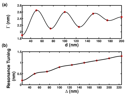
In addition to the splitting into subradiant and superradiant channels, we have found the oscillatory behavior of the linewidths with the distance between the resonators. This signature of the Dicke effect is due to the spatial interference of radiation from decaying quasibound states of the rings coupled to the waveguide at separated locations, inherent to the collective nature of the system. Dicke oscillations of symmetric and antisymmetric modes are translated into further split modes in our case. The effect can be understood analogous to the level repulsion between coherently coupled degenerate bound states Lee and Reichl (2009). Together with the interaction caused splitting of the resonances, interacting (interfering) decay channels also split. Representing linewidths as imaginary parts of the resonances, the symmetric and antisymmetric modes lie out of phase in the complex plane. The interaction channel through the bus waveguide introduces dependent phase accumulation to the mode freely propagating in between the rings along the waveguide. This is translated as a sinusoidal coupling between the rings or a rotation operation in the complex energy plane. By increasing the gap between the rings, the resonances collapse back onto the isolated ring value in a spiraling fashion. During this spiral motion, their imaginary parts periodically become vanishing and finite and hence oscillates.
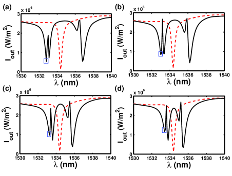
Choosing a resonance, the most energetic one, labeled with a blue box as in Fig. 3(a) at nm, we investigate the dependence of the resonance width and resonance wavelength on the spatial separation between the rings. Fig. 4(a) shows the variation in the width of the resonance as a function of the gap between two ring resonators. The coupling between the rings decreases with distance and the oscillations eventually disappear. The width saturates at the single ring value at long distances. In one-dimensional system of bi-ripple ballistic electron waveguide, sinusoidal periodic behavior of the resonance width is found as the coupling does not decay with the distance Lee and Reichl (2009). Our situation is similar to traditional Dicke systems in higher dimensions, where the coupling decreases with the distance Brandes and Kramer (1999); Shahbazyan and Raikh (1994). Approach to the single ring resonance (resonance tuning) as we increase by an amount is shown in Fig. 4(b). As the coupling decreases with distance, so does the splitting of the collective modes, and thus, the most energetic mode becomes less and less different from the single ring resonance.
Considering now another most energetic resonance found at a larger separation between the rings, labeled with a blue box as in Fig. 3(d) at nm, we examine possible active control of these signatures of the Dicke effect demonstrated in Fig. 4. When the potential applied from the electrodes is turned on, the linewidth and the resonance are changed as shown in Fig. 5. The linewidth decreases with increasing potential, which aligns the directors such that in the coupler zones, the cladding index increases to . This locally reduces the index contrast with the silicon guides and enhances the field penetration, and thus the proximity coupling between the resonators increases. The chosen most energetic mode becomes further split from the single ring resonance with the increasing coupling coefficient. The applied voltage and the spatial separation between the rings have opposite effects on the coupling resonators.
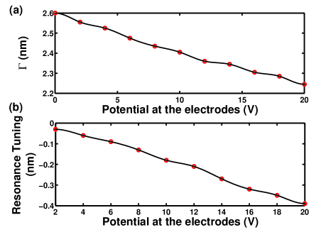
Finally, we analyze the influence of the external potential on the periodicity of as a function . Fig. 6(a) is in agreement with the earlier observations in Fig. 5(a) that the resonance width decreases with the applied voltage. The periodicity of when no voltage is applied (see Fig. 3(a)) is determined to be nm. Change of the period from this value when the potential is applied is denoted by . Fig. 6(b), shows that the periodicity of the increases steadily with the potential applied from the electrodes. Enhanced coupling of the rings increases the splitting of symmetric and antisymmetric modes. For the chosen most energetic resonance, this makes it closer to the waveguide mode. Thus the free propagation and the associated phase accumulation between the rings occurs at smaller frequency or at larger period. In the complex energy plane, that means the rate of rotation with is reduced.
Summarizing, we have examined the resonances and their widths in an all-optical system of a pair of ring resonators side-coupled to an optical waveguide in a NLC environment. We have found that the system exhibits all the key signatures of the Dicke effect, splitting of the lifetimes into slow and fast decaying channels in an oscillatory manner with the separation of the resonators. The energies and the lifetimes of the quasibound states of the resonators can be controlled with the applied voltage, which allows for tunable longer range interactions between the resonators. Such a reversible active control can be used to examine coherent collective effects, decoherence, and superradiant phase transitions. Besides, fine tuning of finesse and full spectral range can be exploited for multi-ring systems, such as CROW Yariv et al. (1999) and SCISSOR Heeber et al. (2002) configurations, as well as rings coupled to multiple waveguides. These systems are subject to many applications, particularly optical logic and memory, filtering, reflectivity and optical switching.
The authors acknowledge useful comments by A. Serpenguzel, H. Altug and H. Tureci.
References
- Dicke (1953) R. H. Dicke, Phys. Rev. 89, 472 (1953).
- Dicke (1954) R. H. Dicke, Phys. Rev. 93, 99 (1954).
- H bner et al. (1996) M. H bner, J. Kuhl, T. Stroucken, A. Knorr, S. W. Koch, R. Hey, and K. Ploog, Phys. Rev. Lett. 76, 4199 (1996).
- Christ et al. (2007) A. Christ, Y. Ekinci, H. H. Solak, N. A. Gippius, S. G. Tikhodeev, and O. J. F. Martin, Phys. Rev. B 76, 201405(R) (2007).
- Brandes (2005) T. Brandes, Phys. Rep. 408, 315 (2005).
- Apel et al. (2008) V. M. Apel, P. A. Orellana, and M. Pacheco, Nanotechnology 19, 355202 (2008).
- Orellana et al. (2006) P. A. Orellana, F. Dominguez, and E. Diez, Physica E 35, 126 (2006).
- Orellana et al. (2004) P. A. Orellana, M. L. L. de Guevara, and F. Claro, Phys. Rev. B 70, 233315 (2004).
- Podivilov and Shapiro (1992) E. V. Podivilov and D. A. Shapiro, JETP Lett. 56, 449 (1992).
- Vorrath and Brandes (2003) T. Vorrath and T. Brandes, Phys. Rev. B 68, 035309 (2003).
- Brandes and Kramer (1999) T. Brandes and B. Kramer, Phys. Rev. Lett 83, 3021 (1999).
- Shahbazyan and Raikh (1994) T. V. Shahbazyan and M. E. Raikh, Phys. Rev. B 49, 17123 (1994).
- Lee and Reichl (2008) H. Lee and L. E. Reichl, Phys. Rev. B 77, 205318 (2008).
- Lee and Reichl (2009) H. Lee and L. E. Reichl, Phys. Rev. B 79, 193305 (2009).
- Blom et al. (1997) F. C. Blom, D. R. van Dijk, H. J. W. M. Hoekstra, A. Driessen, and T. J. A. Popma, Appl. Phys. Lett. 71, 747 749 (1997).
- Hill et al. (2004) M. T. Hill, H. J. S. Dorren, T. de Vries, X. J. M. Leitjens, J. H. den Besten, B. Smalbrugge, Y.-S. Oei, H. Binsma, G.-D. Khoe, and M. K. Smit, Nature 432, 206 (2004).
- Anderson (1961) P. Anderson, Phys. Rev. 124, 41 (1961).
- Fano (1961) U. Fano, Phys. Rev. 124, 1866 (1961).
- Maune et al. (2003) B. Maune, R. Lawson, C. Gunn, A. Scherer, and L. Dalton, Appl. Phys. Lett. 83, 4689 (2003).
- Chremmos and Uzunoglu (2005) I. Chremmos and N. Uzunoglu, IEEE Photonics Tech. Lett. 17, 2110 (2005).
- Chung et al. (2006) Y. Chung, D.-G. Kim, and N. Dagli, Jour. Lightwave Tech. 24, 1865 (2006).
- Saleh and Teich (1991) B. E. A. Saleh and M. C. Teich, Fundamentals of Photonics (Wiley, New York, 1991).
- Dunmar and Toniyama (Wiley-VCH, New York, 1998) D. Dunmar and K. Toniyama, Handbook of Liquid Crystals 1, 215 (Wiley-VCH, New York, 1998).
- Collings (2002) P. J. Collings, Liquid Crystals: Nature’s Delicate Phase of Matter (Princeton University Press, Princeton, 2002).
- Poon et al. (2004a) J. Poon, J. Scheuer, and A. Yariv, IEEE Photon. Technol. Lett. 16, 1331 (2004a).
- Poon et al. (2004b) J. Poon, J. Scheuer, S. Mookherjea, G. T. Paloczi, Y. Huang, and A. Yariv, Opt. Express 12, 90 (2004b).
- (27) For our numerical work, we have mainly used Wolfram Research: Mathematica, The MathWorks: MATLAB and Comsol:Comsol Multiphysics commercial softwares.
- Yariv et al. (1999) A. Yariv, Y. Xu, R. K. Lee, and A. Scherer, Opt. Lett. 24, 711 (1999).
- Heeber et al. (2002) J. E. Heeber, R. W. Boyd, and Q.-H. Park, J. Opt. Soc. Am. B 19, 722 (2002).