MRI investigation of granular interface rheology
using a new cylinder shear apparatus
Abstract
The rheology of granular materials near an interface is investigated through proton magnetic resonance imaging. A new cylinder shear apparatus has been inserted in the MRI device, which allows the control of the radial confining pressure exerted by the outer wall on the grains and the measurement of the torque on the inner shearing cylinder. A multi-layer velocimetry sequence has been developed for the simultaneous measurement of velocity profiles in different sample zones, while the measurement of the solid fraction profile is based on static imaging of the sample. This study describes the influence of the roughness of the shearing interface and of the transverse confining walls on the granular interface rheology.
keywords:
velocimetry , granular material , annular shear , interface , roughness1 Introduction
The interaction of a granular material with a solid interface is of interest in various engineering problems, such as industrial conducts [1], geotechnics [2, 3], and in geophysical situations, such as tectonophysics [4] or gravity flows [5].
At the immediate vicinity of the shearing interface, a thin granular layer, where the shear and dilation is localized, plays a significant role in the stress transmission between the solid interface and the bulk granular material. This rheology is influenced by the roughness of the shearing surface [6, 7, 8, 9, 10, 11, 12].
In this paper, we focus our attention on the annular (Couette) shear geometry, where the material is confined between two cylinders and sheared by the rotation of the inner rough one (see [13] for a recent review). This geometry has been used to measure the rheological properties of granular materials, both in two dimensions [14, 15, 16, 17] and three dimensions [18, 19, 20, 21, 22, 23, 24, 25, 26, 27, 28]. However, the visualization of the granular interface is usually limited to the upper (free surface) or bottom layers (through a transparent glass window) [19, 7, 29]. Following previous magnetic resonance imaging investigation of granular rheology [30, 31, 32, 33]: flows in rotating drum [34, 35, 36, 37], vertical chute [38], annular shear cell [39, 20, 25], segregation and convection under vibration [40, 41, 42, 43, 44, 45, 46, 47], we have used MRI to measure the granular rheology (velocity and solid fraction profiles) well inside the sample.
Sec. 2 is devoted to the description of a new annular shear cell, specially designed to be inserted in a MRI device. Based on a geotechnical cylinder shear apparatus [19, 48, 49, 7, 29, 50, 51], its originality relies on the control of the radial confining pressure exerted by the outer wall on the grains and on the measurement of the torque on the inner shearing cylinder.
Sec. 3 explains the multi-layer MRI velocimetry. MRI velocity measurements were performed using a spin-warp / phase encoding technique previously adapted from [52] and used for routine liquid rheology in annular Couette cells (see for instance [53, 54, 55, 56, 57]). It was here further modified on purpose of quasi-simultaneous assessment of different regions in the sample.
Sec. 4 describes the measurement of the velocity and solid fraction profiles, as well as the shear stress on the shearing wall, from which we deduce the influence of the roughness of the shearing interface and of the transverse confining walls on the granular interface rheology. Our study is restricted to the quasi-static regime (small shear velocity and/or high confining pressure).
Preliminary and complementary results are presented in [7].
2 Annular shear cell
The annular shear cell is inserted in the MRI device through an external support. The figure 1 shows a schematic view of the cell, which components are made of PMMA.
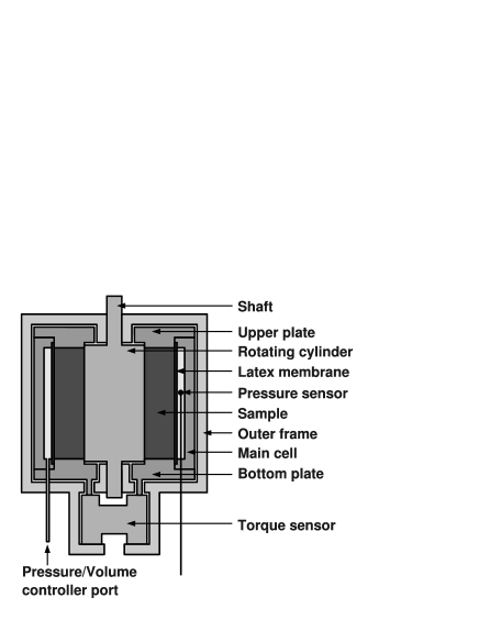
The sample has a hollow cylinder shape. The granular material is confined between two fixed horizontal (bottom and upper) plates (height ), an internal rotating cylinder (radius ) and an external latex homemade dip molded membrane (radius ) filled with water. A pressure-volume controller (GDS®) applies a radial confining pressure to the sample, in the range . An optical fiber sensor (FOP MEMS - Fiso Technologies®) precisely measures this pressure close to the membrane.
The internal rotating cylinder is guided by two journal bearings set in the external support, while the main cell (membrane, bottom and upper plates) is only connected to the external support through the torque sensor, which measures the whole torsion effort.
An aluminum-alloy torque sensor was specially designed, based on resistive strain gages, in the range Nm. This measurement was not possible during MRI experiment, but when displacing the cell bellow the MRI device. This prototype is a first step toward the realization of a torque sensor working inside the MRI device.
Depending on the way upper and bottom plates are mounted, it is possible to measure the whole torsion effort or only the fraction transmitted to the lateral membrane (the difference between those two measurements provides the torque transmitted by the horizontal walls).
The cell is connected to the transmission axis of a rheometer previously designed to be inserted within the MRI facility [58, 56, 59, 60], through a gearbox. This two-stage, timing-belt and pulley system is placed close to the cell and far from the motor. Its reduction factor of provides a rotation range RPS.
This configuration allows to place down the cell (out of the MRI tunnel) during the sample preparation and torque measurement and then move it up to the observation position.
The complete cell has a total diameter of and a total height, without gearbox, of , which fits inside the RF coil.
3 Multi-layer MRI velocimetry
MRI experiments were carried out on a Bruker Biospec MRI facility operating at ( proton frequency). The MRI magnet is a vertical superconducting prototype (Magnex Scientific, Oxford), with a bore. These characteristics are particularly suited for the study of large and inhomogeneous samples, exhibiting strong internal susceptibility contrasts. The magnet is equipped with a birdcage RF coil (height: , inner diameter: , hard pulse duration: ), and a BGA26 shielded gradient system (Bruker), delivering a gradient strength with a rising time of .
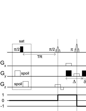
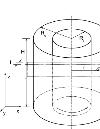
MRI methodology for radial velocimetry inside the cell was that of [52] as further modified by [59] and [60]. It is based on a two-pulse spin echo sequence (Fig. 2a), in which the two pulses are made space-selective in and direction respectively so as to virtually cut a beam along one cell diameter (Fig. 2b). A read-out gradient in directions permits to get after Fourier transform of the signal a 1D magnetization profile along the beam. An additional pair of gradient pulses in direction (in black) induces on the magnetization profile an dependent phase shift reading:
| (1) |
where is the gyromagnetic ratio of proton, the strength of these ’velocity’ pulses, and are timing components of the sequence as described in Fig. 2, and is the velocity component along the selected diameter. In order to get a velocity profile, one performs two MRI measurements with respectively positive and negative velocity gradients, and then compares in each pixel the phase of the two magnetization profiles. When the thickness of the beam in direction is small enough as compared with the cell diameter, such measurement may be regarded as a direct measurement of the orthoradial velocity component versus the radial coordinate (Fig. 2b).
In this sequence, only the phase of NMR signal bears relevant information. It is then safe to use recycling times equal or even shorter than values. Indeed, an incomplete spin-lattice relaxation between two successive sequences may only affect the signal to noise ratio, but is not prone to introduce any bias, provided that the magnetization be correctly cleaned from past solicitations before each sequence. Such cleaning was here performed with a saturation module at the beginning of the delay.
Thanks to saturation, may even be chosen so as to optimize the signal to noise ratio of the experiment. Let’s imagine that, because of experimental constraints, one has a fixed delay to perform a velocity measurement. If some delay is used, then it will be possible to repeat the sequence times. Granted that the available magnetization at the beginning of each sequence scales as , and that the improvement of signal to noise ratio when repeating sequences scales as , the signal to noise ratio of the whole measurement process scales as:
| (2) |
This quantity is maximum for:
| (3) |
and fairly stays above 90% of this maximum in the range . Saturation then turns out a useful tool for signal optimization.
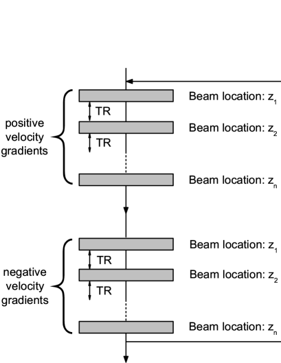
For the assessment of the velocity profiles at different height in direction, sequences were repeated while systematically shifting the vertical position of the beam. In order to study unsteady granular flows, it was important to make these multi-layer measurements as simultaneous as possible.
First of all, looking back at the NMR sequence, the measurement of one beam at a given position clearly affects all the magnetization of a larger region in the cell, composed of the sum of the two slices selected by each RF pulse. This, together with the use of the saturation module, prevents considering measurements at different positions as independent: it is not possible to run the sequence at one height immediately after running the sequence at another height, even if the two associated beams are well separated. Real simultaneous measurements of velocity in multiple layers were then not possible.
We proceeded instead as follows (Fig 3). The whole measurement consisted in two nested loops. In the first loop the vertical location of the beam was shifted after each single sequence, so as to go through all necessary beam positions. The procedure was then just repeated with inverted velocity gradient strength. This first loop was inserted in a second one consisting in standard phase cycling and signal accumulation. One could get this way velocity profiles at different height measured over exactly the same period of time.
In the present work, the thickness of the beam in direction was , and the recycling time was taken as . The typical echo-time was about . Strong enough velocity gradients were here sufficient to select the proper coherence pathway. Our MRI system did not suffer any visible acquisition quadrature defect, so that the phase cycling procedure simply consisted here in a base-line correction, and could be completed in two steps. The minimal value of the height of the beams was . The maximum relevant value was the cell size. Thinner layers are well adapted to study regions with a strong vertical gradient of velocity, like the zone close to the horizontal walls. Because of hardware constraints, the maximum number of layers was . The total experimental time was 13 minutes for three layers of width, 104 minutes for five layers of width and 208 minutes for five layers of width.
4 Experimental results
Three roughness levels of the rotating cylinder are tested: the first one corresponds to a vertically corrugated surface (triangular shape with thickness equal to depth of ), the second one to a glued seeds surface and the third one to sandpaper (medium grain - 80). The horizontal walls (upper and bottom) are originally smooth. To modify their roughness we have sticked sandpaper and glass beads with the same diameter as the seeds (for practical reasons the beads are glued to sandpaper and not directly over the plate surface).
Mustard seeds are used as model granular material (mean diameter , quite monodisperse, mass density of ). The relaxation times are and .
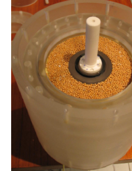
The granular material is poured inside the cell with a funnel from the top and then levelled off (see Fig.4). After closing the cell, the sample is confined by the application of the radial pressure through the membrane. Then, the material is pre-sheared (at least rotations of the cylinder, corresponding to of tangential displacement of the wall) to drive it in a steady-state. Then data acquisition starts.
Tab. 1 summarizes the parametric study (wall roughness, confining pressure and velocity at the wall ).
| cylinder | plates | pressure1 | velocity2 |
| corrugated | smooth | |3.14 | |
| glued seeds | smooth | |3.14 | |
| sandpaper | 8.5 | 3.14 | |
| glass beads | 8.5 | 3.14 | |
| sandpaper | smooth | |3.14 |
1 pressure (kPa) 2 velocity (mm/s)
Internal stresses associated to gravity (of the order of 0,7 kPa) can be considered to be dominated by the applied confining pressures.
The maximum value of the inertial number [13], used to qualify the granular flow regime, can be estimated around , indicating that the granular material is in the quasi-static regime.
We now discuss the radial profiles of velocity and solid fraction. They are presented as a function of , normalized by the diameter of the grains.
4.1 Velocity profiles
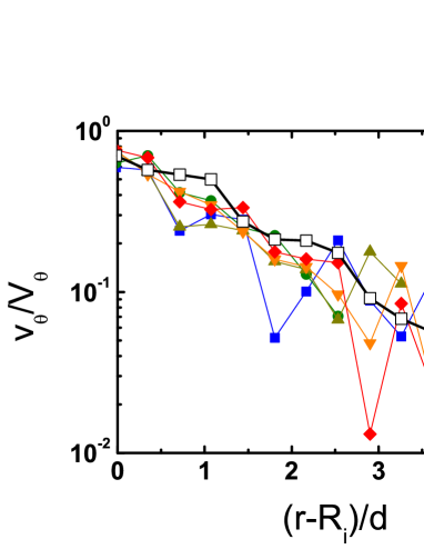
We have first measured the profiles of the orthoradial velocity , normalized by , far from the horizontal walls, comparing three layers thick separated by (Fig. 5).

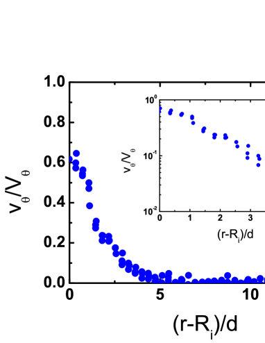
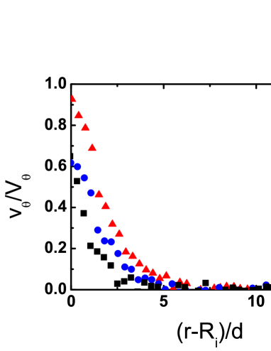
Fig.6 shows that , which signifies that there is significant sliding at the wall. Fig.6 also shows that there is no influence of the roughness of the horizontal walls in the central zone. An approximately exponential decay of the orthoradial velocity profiles is measured, with a maximum value at the shearing wall, consistently with previous studies [18, 19, 20, 14, 29, 13, 15, 25]. Qualitatively, this shear localization is explained by the strong decrease of the shear stress away from the inner wall, while the normal stress remains approximately constant. As expected in the quasi-static regime, no influence of the velocity at the wall nor of the confining pressure has been observed.

4.1.1 Influence of the roughness of the horizontal walls
In a system, the shear stress is entirely transmitted from the inner to the outer wall by the granular material [7, 13]. In a system, the granular material interacts with the horizontal walls, to which part of the torque is transmitted. This changes the stress distribution within the sample, and may consequently affect the velocity profile. This influence of frictional lateral walls has been evidenced in granular surface flows between vertical walls [61], especially when they are rough [62]. We now wonder if such effect is observed close to the horizontal walls.
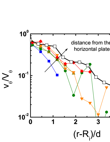
The analysis of the influence of the horizontal walls was based on a comparison of the profiles of layers thick separated by a distance of (Fig. 7). The gap of between the horizontal wall and the first layer ensured that only moving particles were considered in the measure. In the rough case, a similar gap was taken from the glued glass beads surface giving a total thickness of .


The horizontal roughness made of glass beads is not detectable by MRI, which provided a correct evaluation of the velocity of the grains in direct contact with this surface. The motion of the grains could be clearly distinguished from the motion of the cylinder, given the strong velocity gradient.
Fig. 8 shows a comparison between the profiles in the central zone and near the horizontal wall. In the case of a smooth horizontal wall, there is no significant influence. This result has practical applications, validating the measure of displacements of granular materials through transparent glass walls [19, 7, 29]. Conversely, in the case of a rough horizontal wall, a significant decrease is observed very close to the horizontal wall, particularly in the first layer. This indicates the transmission of shear stress between the granular material and the horizontal walls. However, the perturbation remains very localized, in contrast with granular surface flows [62]. The fluctuations of the velocity profiles in the first layers close to the horizontal wall is explained by the small thickness of those layers, which strongly decreases the signal to noise ratio.
4.1.2 Influence of the cylinder roughness
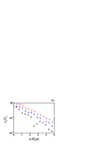
Fig. 9 shows that the cylinder roughness has a significant influence on the velocity , causing offsets of the whole velocity profiles. Sliding, defined as the ratio between the maximum value of the particle velocity and the wall velocity [29, 13], decreases from sandpaper cylinder to the corrugated one, that is to say as the roughness increases.
4.2 Friction coefficient
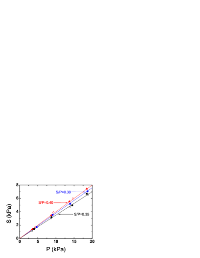
The average shear stress at the inner cylinder is simply deduced from the measured torque as . Consistently with previous studies [63, 50, 9, 10], a linear relation between the shear stress and the confining pressure is observed (Fig. 10), from which an effective friction coefficient is deduced (considering that the normal stress at the cylinder wall is approximately equal to ) for each of the three cylinders: for sandpaper, for glued seeds and for corrugation. This increase seems consistent with the decrease of the particle sliding shown in Fig. 9. The roughness of the horizontal walls does not affect this value, which is consistent with the very localized influence of this roughness.
4.3 Solid fraction profile
In order to measure the influence of the shear on the radial distribution of grains, spin density pictures ( layers thick in direction, with a space resolution of in both and directions) were performed at rest before and after shearing (at least rotations, making of tangential displacement). Fig. 11a and Fig. 11b show typical density pictures obtained before and after shearing respectively.
For each radial coordinate, grayscale pictures were then integrated together in the orthoradial direction. Granted that the integrated spin density profile in radial direction provides a relative measurement of the solid fraction, these solid fractions are normalized by the mean value obtained before shearing, and shown in Fig. 12.

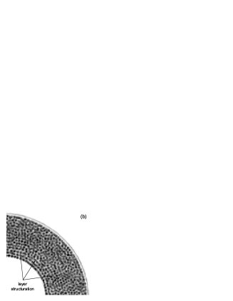
Before shearing, after the granular material has been poured in the cell, the solid fraction is relatively homogeneous, with a certain structuration ( oscillations) near the inner wall. After shearing, a much clearer structuration (already visible on the static images (Fig. 11)) together with a significant dilation is observed close to the shearing cylinder (). However, the zone does not reveal significant solid fraction changes. This indicates that most of the volumetric variations are localized in the region near the cylinder, as reported by other experiments and simulations [7, 29, 13].

5 Conclusions
As a way to study the rheology of granular materials near an interface, we have developed a cylinder shear apparatus inserted in the MRI device, which allows the control of the radial confining pressure exerted by the outer wall on the grains and the measurement of the torque on the inner shearing cylinder. We have also developed a multi-layer velocimetry sequence for the simultaneous measurement of velocity profiles in different sample zones. This study shows that the roughness of the shearing interface significantly affects the granular interface rheology (sliding velocity and friction coefficient), while the influence of the roughness of the transverse confining walls remains localized in the very first layers. Moreover the measurement of the solid fraction profiles, based on static imaging of the sample, shows that, when starting to shear the material, its volumetric variations remains localized close to the shearing interface. Those data are useful to test models attempting to describe granular interface rheology [64, 15, 65] for annular shear. Using this device together with the velocimetry sequence, work is under progress to study the transient behavior of the granular material, under monotonic or cyclic shear, and the influence of liquid saturation.
References
- [1] R.M. Nedderman. Statics and kinematics of granular materials. Cambridge University Press, Cambridge, 1992.
- [2] F. Schlosser and V. Elias. Friction in reinforced earth. In Proceedings of the International Symposium on Earth Reinforcement, pages 735–763, Pittsburgh, Pennsylvania, April 1978.
- [3] J.T. Tubacanon, D.W. Airey, and H.G. Poulos. Pile skin friction in sands from constant normal stiffness tests. Geotechnical Testing Journal, 18(3):350–364, 1995.
- [4] G. Chambon, J. Schmittbuhl, and A. Corfdir. Frictional response of a thick gouge sample: 2. friction law and implications for faults. J. Geophys. Res., 111:B09309, 2006.
- [5] F. Chevoir. Granular flows (in French). Laboratoire Central des Ponts et Chaussées - Collection Etudes et Recherches des Laboratoires des Ponts et Chaussées, 2009.
- [6] J.T. DeJong, M.F. Randolph, and D.J. White. Interface load transfer degradation during cyclic loading: a microscale investigation. Soils and Foundations, 43(4):81–93, 2003.
- [7] G. Koval. Interface behavior of granular materials (in French). PhD thesis, École des Ponts Paristech, Paris, 2008. http://tel.archives-ouvertes.fr/tel-00311984.
- [8] T.A. Oumarou and E. Evgin. Cyclic behaviour of a sand-steel plate interface. Can. Geotech. J., 42:1695–1704, 2005.
- [9] M. Uesugi and H. Kishida. Influential factors of friction between steel and dry sands. Soils and Foundations, 26:33–46, 1986.
- [10] M. Uesugi and H. Kishida. Frictional resistance at yield between dry sands and steel. Soils and Foundations, 26:139–149, 1986.
- [11] M. Uesugi, H. Kishida, and Y. Tsubakihara. Behavior of sand particules in sand-steel friction. Soils and foundations, 28(1):107–118, 1988.
- [12] I. Vardoulakis and P. Unterreiner. Interfacial localisation in simple shear tests on a granular medium modelled as a cosserat continuum. In A.P.S. Selvadurai and M. Boulon, editors, Mechanics of Geomaterial Interfaces, volume 42, pages 487–512, 1995.
- [13] G. Koval, J-N. Roux, A. Corfdir, and F. Chevoir. Annular shear of cohesionless granular materials: From the inertial to quasistatic regime. Phys. Rev. E, 79:021306, 2009.
- [14] D. Howell, R.P. Behringer, and C.T. Veje. Stress fluctuations in a 2D granular Couette experiment : a continuum transition. Phys. Rev. Lett., 82:5241–5244, 1999.
- [15] M. Latzel, S. Luding, H.J. Herrmann, D.W. Howell, and R.P. Behringer. Comparing simulation and experiment of a 2D granular Couette shear device. Euro. Phys. J. E, 11:325–333, 2003.
- [16] B. Miller, C. O’Hern, and R. P. Behringer. Stress fluctuations for continuously sheared granular materials. Phys. Rev. Lett., 77:3110–3113, 1996.
- [17] C.T. Veje, D.W. Howell, and R.P. Behringer. Kinematics of two - dimensional granular Couette experiment at the transition to shearing. Phys. Rev. E, 59:739–745, 1999.
- [18] L. Bocquet, W. Losert, D. Schalk, T. C. Lubensky, and J. P. Gollub. Granular shear flow dynamics and forces : Experiment and continuous theory. Phys. Rev. E, 65:011307, 2002.
- [19] G. Chambon, J. Schmittbuhl, A. Corfdir, J.-P. Vilotte, and S. Roux. Shear with comminution of a granular material: Microscopic deformations outside the shear band. Phys. Rev. E, 68:011304, 2003.
- [20] F. da Cruz. Flow of dry grains : Friction and jamming (in French). PhD thesis, École des Ponts Paristech, Paris, 2004. http://pastel.paristech.org/archive/00000946.
- [21] F. da Cruz, F. Chevoir, D. Bonn, and P. Coussot. Viscosity bifurcation in granular materials, foams, and emulsions. Phys. Rev. E, 66:051305, 2002.
- [22] R.C. Daniel, A.P. Poloski, and A.E. Saez. Vane rheology of cohesionless glass beads. Powder Tech., 179:62–73, 2007.
- [23] W. Losert and G. Kwon. Transition and steady-state dynamics of granular shear flows. Advances in complex systems, 4:369–377, 2001.
- [24] D.M. Mueth. Mesurement of particule dynamics in slow, dense granular Couette flow. Phys. Rev. E, 67:011304, 2003.
- [25] D.M. Mueth, G.F. Debregeas, G.S. Karczmar, P.J. Eng, S.R. Nagel, and H.M. Jaeger. Signature of granular microstructure in dense shear flows. Nature, 406:385–389, 2000.
- [26] G.I. Tardos, M.I. Khan, and D.G. Schaeffer. Forces on a slowly rotating, rough cylinder in a Couette device containing a dry, frictional powder. Phys. Fluids, 10:335–341, 1998.
- [27] G.I. Tardos, S. McNamara, and I. Talu. Slow and intermediate flow of a frictional bulk powder in the Couette geometry. Powder Tech., 131:23–39, 2003.
- [28] P. Wang, C. Song, C. Briscoe, and H.A. Makse. Particle dynamics and effective temperature of jammed granular matter in a slowly sheared 3D Couette cell. Phys. Rev. E, 77:061309, 2008.
- [29] G. Koval, F. Chevoir, J.-N. Roux, J. Sulem, and A. Corfdir. Slow annular shear of granular-continuum interfaces: macroscopic and mesoscopic observations. submitted to Granular Matter, 2009.
- [30] E. Fukushima. Nuclear magnetic resonance as a tool to study flow. Annu. Rev. Fluid Mech., 31:95–123, 1999.
- [31] E. Fukushima. NMR Imaging in Chemical Engineering, chapter Granular flow, pages 490–508. Wiley-VCH, 2006.
- [32] V. Y. Kuperman. Nuclear magnetic resonance measurements of diffusion in granular media. Phys. Rev. Lett., 77:1178–1181, 1996.
- [33] M. Nakagawa, S.A. Altobelli, A. Caprihan, E. Fukushima, and E.K. Jeong. Non-invasive measurements of granular flow by magnetic resonance imaging. Exp. in Fluids, 16:54–60, 1993.
- [34] A. Caprihan and J.D. Seymour. Correlation time and diffusion coefficient imaging : application to granular flow system. Journal of Magnetic Resonance, 144:96–107, 2000.
- [35] G.H. Ristow and M. Nakagawa. Shape dynamics of interfacial front in rotating cylinders. Phys. Rev. E, 59:2044–2048, 1999.
- [36] J. D. Seymour, A. Caprihan, S. Altobelli, and E. Fukushima. Pulsed gradient spin echo nuclear magnetic resonance imaging of diffusion in granular flow. Phys. Rev. Lett., 84:266–269, 2000.
- [37] K. Yamane, M. Nakagawa, S. A. Altobelli, T. Tanaka, and Y. Tsuji. Steady particulate flows in a horizontal rotating cylinder. Phys. Fluids, 10:1419–1427, 1998.
- [38] F. Chevoir, M. Prochnow, P. Moucheront, F. da Cruz, F. Bertrand, J.P. Guilbaud, P. Coussot, and J.N. Roux. Dense granular flows in a vertical chute. In Y. Kishino, editor, Powders and grains 2001, pages 399–402, Rotterdam, 2001. Balkema.
- [39] X. Cheng, J. B. Lechman, A. Fernandez-Barbero, G. S. Grest, H. M. Jaeger, G. S. Karczmar, M. E. Möbius, and S. R. Nagel. Three-dimensional shear in granular flow. Phys. Rev. Lett., 96:038001, 2006.
- [40] A. Caprihan, E. Fukushima, A. D. Rosato, and M. Kos. Magnetic resonance imaging of vibrating granular beds by spatial scanning. Rev. Sci. Instrum., 68:4217––4220, 1997.
- [41] E. E. Ehrichs, H. M. Jaeger, G. S. Karczmar, J. B. Knight, V. Y. Kuperman, and S. R. Nagel. Granular convection observed by magnetic resonance imaging. Science, 267:1632–1634, 1995.
- [42] K. M. Hill, A. Caprihan, and J. Kakalios. Bulk segregation in rotated granular material measured by magnetic resonance imaging. Phys. Rev. Lett., 78:50–53, 1997.
- [43] J. B. Knight, E. E. Ehrichs, V. Y. Kuperman, J. K. Flint, H. M. Jaeger, and S. R. Nagel. Experimental study of granular convection. Phys. Rev. E, 54:5726–5738, 1996.
- [44] V. Y. Kuperman, E. E. Ehrichs, H. M. Jaeger, and G. S. Karczmar. A new technique for differentiating between diffusion and flow in granular media using magnetic resonance imaging. Rev. Sci. Instrum., 66:4350–4355, 1995.
- [45] G. Metcalfe and M. Shattuck. Pattern formation during mixing and segregation of flowing granular materials. Physica A, 233:709 – 717, 1996.
- [46] X. Yang and D. Candela. Potential energy in a three-dimensional vibrated granular medium measured by NMR imaging. Phys. Rev. Lett., 85:298–301, 2000.
- [47] X. Yang, Y. Huan, D. Candela, R.W. Mair, and R.L. Walsworth. Measurement of grain motion in a dense, three-dimensional granular fluid. Phys. Rev. Lett., 88:044301, 2002.
- [48] A. Corfdir, P. Lerat, and I. Vardoulakis. A cylinder shear apparatus. Geotechnical Testing Journal, 27:447–455, 2004.
- [49] A.I. Dumitrescu. Experimental study of the interface behavior between a structure and a granular soil (in French). PhD thesis, École des Ponts Paristech, Paris, 2005.
- [50] P. Lerat. Study of the soil - structure interface in granular media by using a new ring shear apparatus (in French). PhD thesis, École des Ponts Paristech, Paris, 1996.
- [51] P. Lerat, M. Boulon, and F. Schlosser. Experimental study of the soil - structure interface in granular media. Revue Française de Génie Civil, 1:345–366, 1997.
- [52] A.D. Hanlon, S.J. Gibbs, L.D. Hall, D.E. Haycock, W.J. Frith, and S. Ablett. Rapid MRI and velocimetry of cylindrical Couette flow. Magn. Reson. Imaging, 16:953–961, 1998.
- [53] D. Bonn, S. Rodts, M. Groenink, S. Rafaï, N. Shahidzadeh-Bonn, and P. Coussot. Some applications of magnetic resonance imaging in fluid mechanics: Complex flows and complex fluids. Annu. Rev. Fluid Mech., 40:209–233, 2008.
- [54] N. Huang, G. Ovarlez, F. Bertrand, S. Rodts, P. Coussot, and D. Bonn. Flow of wet granular materials. Phys. Rev. Lett., 94:028301, 2005.
- [55] S. Jarny, N. Roussel, S. Rodts, F. Bertrand, R. Le Roy, and P. Coussot. Rheological behavior of cement pastes from MRI velocimetry. Cement and Concrete Research, 35:1873–1881, 2005.
- [56] G. Ovarlez, F. Bertrand, and S. Rodts. Local determination of the constitutive law of a dense suspension on noncolloidal particles through magnetic resonance imaging. J. Rheol., 50:256–292, 2006.
- [57] G. Ovarlez, S. Rodts, A. Ragouilliaux, P. Coussot, J. Goyon, and A. Colin. Wide-gap couette flows of dense emulsions: Local concentration measurements, and comparison between macroscopic and local constitutive law measurements through magnetic resonance imaging. Phys. Rev. E, 78:036307, 2008.
- [58] P. C. F. Møller, S. Rodts, M. A. J. Michels, and D. Bonn. Shear banding and yield stress in soft glassy materials. Phys. Rev. E, 77:041507, 2008.
- [59] J.S. Raynaud, P. Moucheront, J.C. Baudez, F. Bertrand, J.P. Guilbaud, and P. Coussot. Direct determination by nmr of the thixotropic and yielding behavior of suspensions. J. Rheol., 46:709–732, 2002.
- [60] S. Rodts, F. Bertrand, S. Jarny, P. Poullain, and P. Moucheront. Recent developments in MRI applications to rheology and fluid mechanics. Comptes Rendus Chimie, 7:275 –282, 2004.
- [61] P. Jop, Y. Forterre, and O. Pouliquen. Crucial role of sidewalls in granular surface flows: consequences for the rheology. 541:167–192, 2005.
- [62] P. Jop, Y. Forterre, and O. Pouliquen. A constitutive law for dense granular flows. Nature, 441:727–730, 2006.
- [63] C. Coste. Shearing of a confined granular layer: Tangential stress and dilatancy. Phys. Rev. E, 70:051302, 2004.
- [64] L. S. Mohan, K. K. Rao, and P. R. Nott. Frictional Cosserat model for slow shearing of granular materials. 457:377–409, 2002.
- [65] R. Artoni, P. Canu, and A. Santomaso. Effective boundary conditions for dense granular flows. Phys. Rev. E, 79:031304, 2009.