S.V. Kosarevsky 22institutetext: Faculty of Technology,
Saint-Petersburg Institute of Mechanical-Engineering,
Saint-Petersburg, Russia 195197
22email: kosarevsky@linderdaum.com 33institutetext: V.N. Latypov 44institutetext: Faculty of Applied Mathematics and Control Processes,
Saint-Petersburg State University,
Saint-Petersburg, Russia 198504
Inertia compensation while scanning screw threads on coordinate-measuring machines
Abstract
Usage of scanning coordinate-measuring machines for inspection of screw threads has become a common practice nowadays. Compared to touch trigger probing, scanning capabilities allow to speed up measuring process while still maintaining high accuracy. However, in some cases accuracy drasticaly depends on the scanning speed. In this paper a compensation method is proposed allowing to reduce the influence of some dynamic effects while scanning screw threads on coordinate-measuring machines.
Keywords:
scanning CMM accuracy1 Introduction
Numerical compensation of measurement errors is a well developed field of dimensional metrology GUM . This type of compensation originates from different CAA (computer-aided accuracy) methods and is extensively used in modern CMMs and CNC machines during recent years Trapet97 , Jenq95 .
To successfully compensate measurement results one should clearly undertand the exact source of errors. Measuring uncertainty on coordinate-measuring machines depends on many factors. They can be summarized into the following types Schwenke08 :
-
•
kinematic;
-
•
thermo-mechanical;
-
•
loads;
-
•
dynamic;
-
•
control software.
Some dynamic effects produce non-constant measurement errors varying according to known models. These models depend entirely upon specific measurement task and development of generic model is troublesome. One of the widely accepted example of such kind of model is pretravel compensation Estler96 , Woz03-1 , Woz03-2 .
In this paper a novel compensation method is given to reduce minor and major diameters measurement error from dynamic effects emerging while scanning screw threads.
2 Related work
Due to inertial forces while high-speed scanning freeform workpieces with low radius of curvature on coordinate-measuring machines it is difficult for the control software to maintain stable contact between the probe and the surface. This is one of the reasons preventing accurate scanning at high speeds Pereira07 . The study of dynamic effects was conducted by many researchers. Application of signal analysis and processing theory to dimensional metrology was studied in Hessling08 . Pereira and Hocken Pereira07 proposed classification and compensation methods for dynamic errors of scanning coordinate-measuring machines. They used Taylor series and Fourier analysis to compensate measurement of circular features. ISO 10360 ISO10360 defines acceptance tests for scanning coordinate-measuring machines. Farooqui and Morse Far07 proposed reference artifacts and tests to compare scanning performance of different coordinate-measuring machines. Szelewski et al. Szel07 conducted experimental research and concluded that freeform surfaces scanning time reduction is limited at high speeds by acceleration and deceleration of the probing system.
3 Theoretical model of probe inertial motion
High-speed longitudinal scanning of a thread surface results in loss of contact between the probe and the thread surface. Because of this coordinate-measuring machine will measure points not belonging to the thread surface. The actual value of the minor diameter (for internal threads) or the major diameter (for external threads) can be distorted. This effect is noticeable at scanning speeds above 5 mm/s and the probing system mass of over 0.1 kg.
The “helix” scanning strategy is free from this effect since no surface part with low radius of curvature is scanned at high speed.
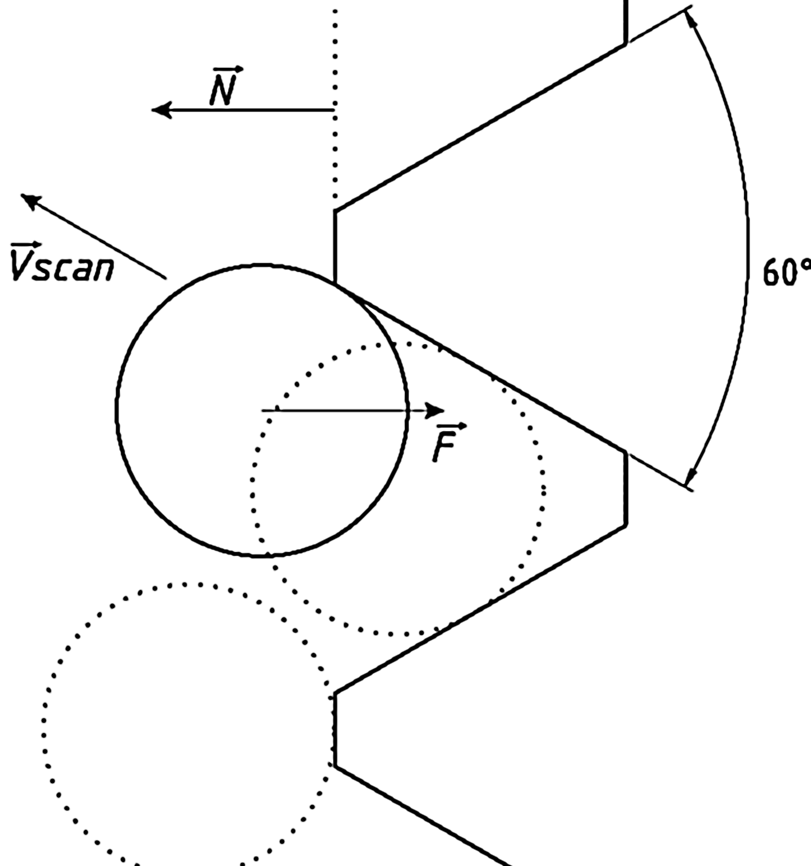
Energy conservation yields (fig. 1):
| (1) |
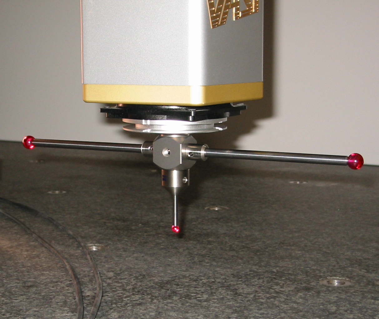
where is the mass of the probing system floating inside the CMM probing head (fig. 2), kg; is the scanning speed, m/s; is the contact force, N; is the unit vector othogonal to the thread axis; is the separation of the probe from the surface, m.
Assuming that →N and →F are collinear the separation value can be derived from the equation (1):
where is the thread angle.
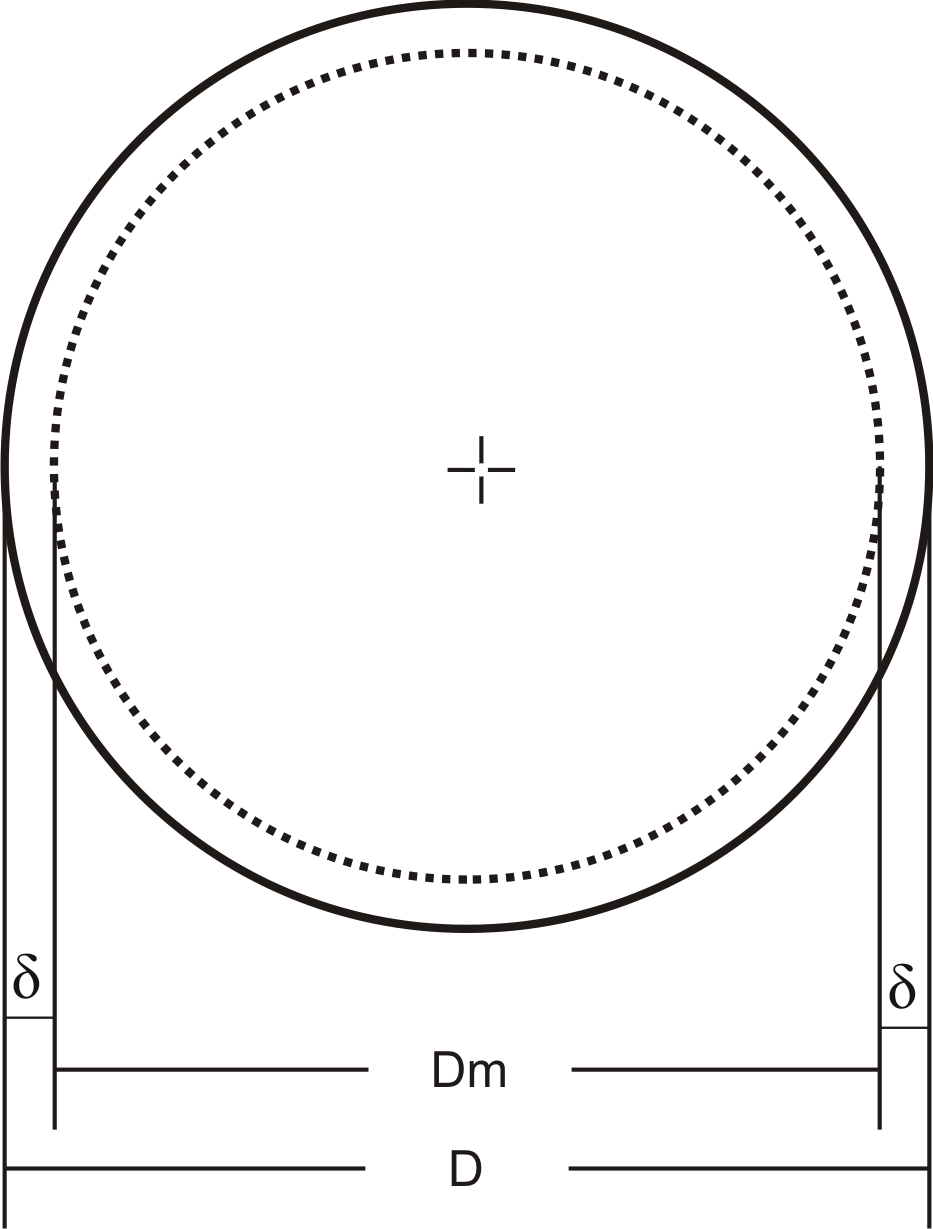
Since the separation is axisymmetric (fig. 3) the diameter measurement error is
| (2) |
4 Compensation
The equation (2) can be used to obtain the diameter compensation formula:
where is the compensated diameter, m (fig. 3); is the measured diameter, m. The upper sign applies to internal threads and the lower sign to external threads respectively.
5 Experimental verification of the model
We scanned the ISO metric screw thread ring gauge M170x6 ISO68 to measure its minor diameter. The diameter was calculated as the maximal inscribed cylinder with both filtering and outlier elimination disabled. The mass of our probing system was 0.1 kg according to manufacturer’s specification, contact force was set in CMM software to 0.2 N.
Theoretical and experimental values for different scanning speeds are summarized in table 1.
Experimental values were obtained on a Carl Zeiss PRISMO 10 S-ACC () coordinate-measuring machine. The value of the minor diameter scanned at 1 mm/s was assumed to be the actual value (). Each of the resulted experimental errors were averaged by 10 measurements.
| Speed, mm/s | Separation , | , | , | , | Reduction, % |
|---|---|---|---|---|---|
| 1 | 0.2 | 0.4 | 0.0 | -0.4 | 0.0 |
| 2 | 0.8 | 1.5 | 0.4 | -1.1 | 26.7 |
| 3 | 1.7 | 3.4 | 1.8 | -1.6 | 53.0 |
| 4 | 3.0 | 6.0 | 2.0 | -4.0 | 33.3 |
| 5 | 4.7 | 9.4 | 3.1 | -6.3 | 33.0 |
| 6 | 6.8 | 13.5 | 11.0 | -2.5 | 81.5 |
| 7 | 9.2 | 18.4 | 11.9 | -6.5 | 64.7 |
| 8 | 12.0 | 24.0 | 31.6 | 7.6 | 68.3 |
| 9 | 15.2 | 30.4 | 37.6 | 7.2 | 76.3 |
| 10 | 18.8 | 37.5 | 46.1 | 8.6 | 77.1 |
| 11 | 22.7 | 45.4 | 38.5 | -6.9 | 84.8 |
| 12 | 27.0 | 54.0 | 40.6 | -13.4 | 75.2 |
| 13 | 31.7 | 63.4 | 80.2 | 16.8 | 73.5 |
| 14 | 36.8 | 73.5 | 90.8 | 17.3 | 76.5 |
| 15 | 42.2 | 84.4 | 123.7 | 39.3 | 53.4 |
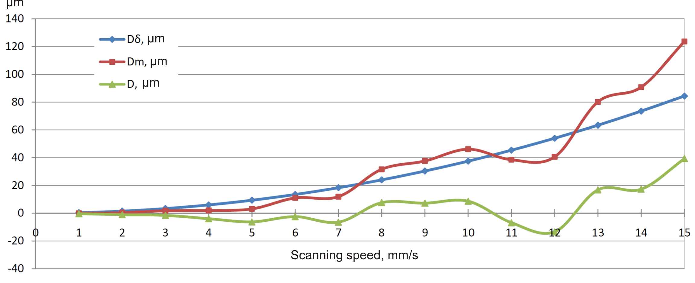
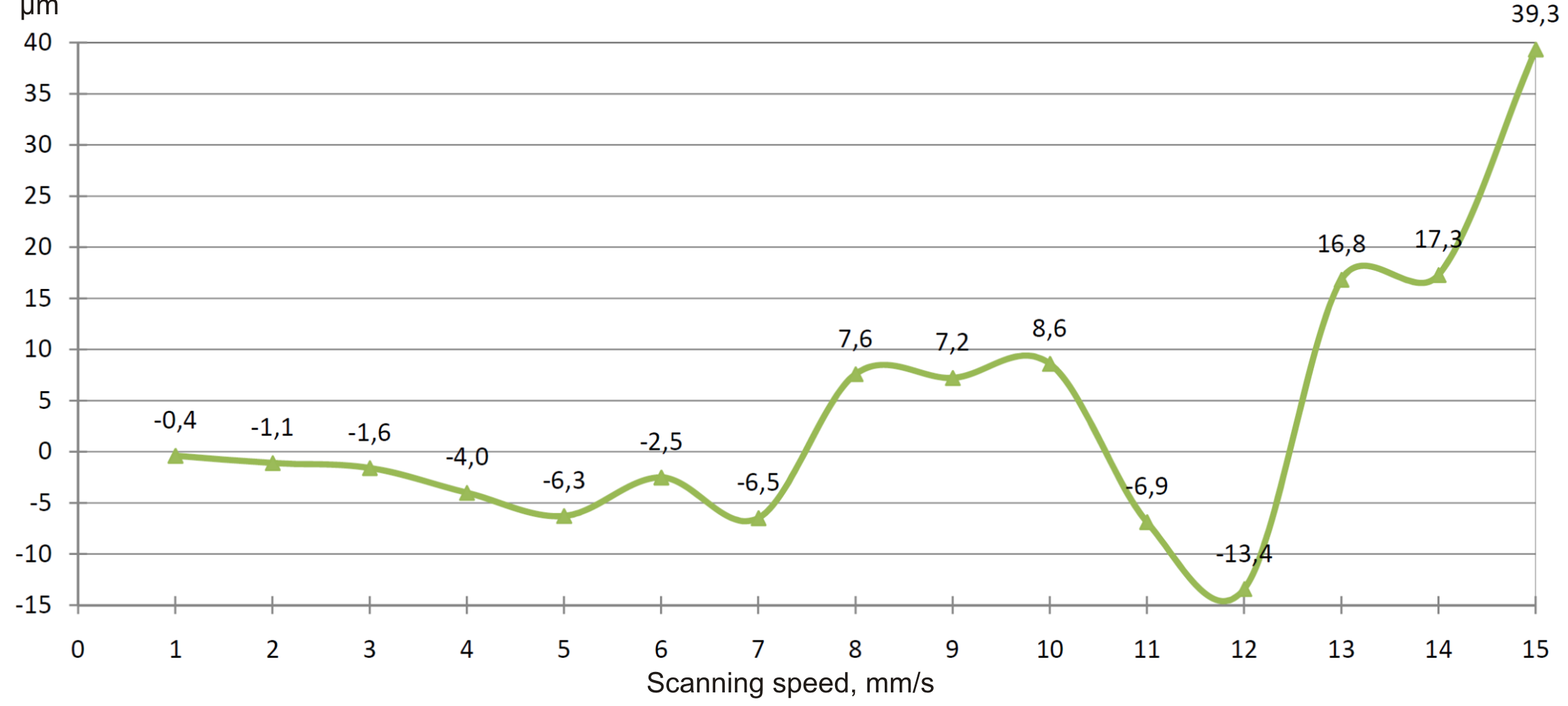
Plots of the estimated error (), the experimental error () and the compensated error () are displayed in fig. 4. The compensated error is also individually shown in fig. 5.
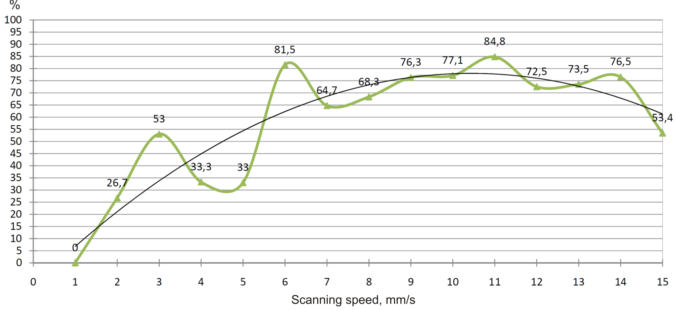
The percentage of error reduction was calculated as
and is displayed in fig. 6. Quadratic least-squares approximation (black) is shown for reference.
6 Conclusions
The most significant error reduction (fig. 6) can be achieved in the interval of scanning speeds from 6 mm/s and up to 12 mm/s. At scanning speeds below 5 mm/s the influence of the studied effect is surpassed by the value of the tested CMM and cannot be treated unambiguously (note large fluctuations in error reduction at speeds below 5 mm/s). At speeds above 12 mm/s the compensated error is quickly surpassing 20 and can be unaccaptable for the most practical applications.
Even though the mass of the probing system was taken directly from the manufacturer’s specification and no actual mass measurement was performed the calculated compensation values has proven to be useful.
Though numerical compensation of the measurement results is a rapidly growing field of dimensional metrology its application to dynamic effects compensation is to be extended. Experimental activities described in this paper confirm the method proposed is able to reduce the influence of interia of the probing system on measurement error of screw thread’s minor and major diameters. This method can be easily implemented directly in CMM software to allow automatic inertia compensation.
7 Acknowledgement
This work was carried out with the support of the OPTEC — Carl Zeiss grant 2010, http://optec.zeiss.ru.
References
- (1) ISO GUM 1995 Guide to the Expression of Uncertainty in Measurement. BIPM, IEC, IFCC, ISO, IUPAC and OIML. Second Edition. 1995.
- (2) Trapet, E.; Wäldele, F. Coordinate Metrology — Flexebility in conflict with accuracy? // Anais — Seminário Internacional de Metrologia, Florianopolis – SC, 1997.
- (3) Jenq-Shyong, C. Computer-aided accuracy enhancement for multi-axis CNC machine tool // International Journal of Machine Tools and Manufacture, Vol.35, Issue 4, April 1995, pp. 593-605.
- (4) Schwenke, H.; Knapp, W.; Haitjema, H.; Weckenmann, A.; Schmitt, R.; Delbressine, F. Geometric error measurement and compensation of machines — An update // CIRP Annals — Manufacturing Technology, 2008, 57, pp. 660-675.
- (5) Estler, W.T.; Phillips, S.D.; Borchardt, B.; Hopp, T.; Witzgall, C.; Levenson, M.; Eberhardt, K.; McClain, M.; Shen, Y.; Zhang, X. Error compensation for CMM touch trigger probes // Precision Engineering. Vol. 19, 2, October 1996, pp. 85-97(13).
- (6) Woźniak, A.; Dobosz, M. Metrological feasibilities of CMM touch trigger probes. Part I: 3D theoretical model of probe pretravel // Measurement. Vol. 34, Issue 4, December 2003, pp. 273-286.
- (7) Woźniak, A.; Dobosz, M. Metrological feasibilities of CMM touch trigger probes. Part II: Experimental verification of the 3D theoretical model of probe pretravel // Measurement. Vol. 34, Issue 4, December 2003, pp. 287-299.
- (8) Pereira, P. H.; Hocken, R. J. Characterization and Compensation of Dynamic Errors of a Scanning Coordinate Measuring Machine // Precis. Eng., 2007, 31(1), pp. 22-32.
- (9) Hessling, J.P. Dynamic metrology — an approach to dynamic evaluation of linear time-invariant measurement systems // Measurement Science and Technology, Vol. 19, 2008.
- (10) Szelewski, M.; Grzelka, M.; Barisic, B. Free surface scanning with CMM and its reproduction in CAD system // Engineering Review, 27-1, 2007. pp. 7-12.
- (11) ISO 10360-4:2000 Geometrical Product Specifications (GPS) — Acceptance and reverification tests for coordinate measuring machines (CMM) — Part 4: CMMs used in scanning measuring mode.
- (12) Farooqui, A.; Morse P. Methods and artifacts for comparison of scanning CMM performance // Transactions of the ASME, Vol.7, March 2007, pp. 72-80.
- (13) ISO 68-1 ISO general purpose screw threads — Basic profile — Metric screw threads.
- (14) ISO 11562:1996 Geometrical Product Specifications (GPS) — Surface Texture: Profile Method — Metrological Characteristics of Phase Correct Filters (Geneva, Switzerland: International Organization for Standardization).