An Anisotropic Metamaterial Leaky Waveguide
Huikan Liu and Kevin J. Webb
School of Electrical and Computer Engineering, Purdue University, West Lafayette, IN 47907, USA
Email: webb@purdue.edu
Abstract
We propose a leaky optical waveguide achieved with a uniaxially anisotropic metamaterial that supports both forward and backward leaky waves. The backward leaky nature is exploited in a sub-diffraction imaging system.
© 2009 Optical Society of America
OCIS codes: 160.3918, 260.2110
Leaky wave antennas can offer high directivity and frequency scanning [1]. An isotropic dielectric slab with refractive index , which supports guided modes, does not radiate effectively unless spatial variations are introduced to excite fast-wave space harmonics [1]. Translating such components to nanophotonics presents fabrication difficulties. To realize uniform leaky wave structures, potentially in the optical domain, a metamaterial slab with that leads to enhanced radiation directivity has been proposed and investigated [2, 3]. This approach suffers the limitation of large transverse slab dimensions, because the operating wavelength inside the slab is much greater than the free space wavelength due to the small value of [4]. Low refractive index metamaterials that require small material permeabilities face challenges of implementation [3]. In addition, radiation occurs in a narrow angular range between broadside and the critical angle , which presents a restriction for beam scanning. Finally, we note that while a microstrip transmission line loaded with series capacitors and shunt inductors has been studied to realize metamaterial leaky-wave antennas in the microwave frequency regime [5], identifying the optical counterparts of shunt inductors and series capacitors is difficult. To overcome these limitations, we present a forward/backward radiating leaky waveguide at optical wavelengths based on non-magnetic uniaxially anisotropic metamaterials having permittivity tensors in which one component is different from the others in sign [6]. The resulting hyperbolic dispersion relation enables radiation from backfire () to endfire (), and the slab thickness can be small relative to the free space wavelength.
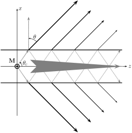

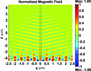
We consider the anisotropic waveguide configuration of Fig. 1LABEL:sub@fig:Schematic, where a transverse magnetic (TM) wave () is excited by a magnetic line current source located at and travels in the direction with a propagation constant . This excitation generates all the even modes of the structure, in terms of . The anisotropic slab can be characterized by a dielectric tensor , with , and the surrounding medium is assumed to be free space. The TM fields in the anisotropic slab have a dispersion relation , and in free space, . Leaky modes of the structure are not confined to the slab, i.e., is approximately real, which leads to the requirement that and [1]. The radiation occurs at angle with respect to the broadside direction. In the regime , the longitudinal wavenumber inside the anisotropic slab can be approximately expressed as , where the sign depends on the signs of and , namely, “” is assumed if and , whereas and leads to “” [7]. Numerical analysis reveals that the slab is capable of supporting a fast wave () and leaking power along the waveguide given appropriate values of . A mathematically sufficient condition for the dielectric tensor for leakage into free space is that , which is a salient sign of anisotropic -near-zero metamaterials [8]. If and , the structure leaks forward; if and , the structure radiates backward. The forward/backward propagation characteristics are direct consequences of the right/left-handedness of strongly anisotropic media [9]. In Figs. 1LABEL:sub@fig:FHField and 1LABEL:sub@fig:BHField, we show the field distributions of forward and backward leaky waveguides with subwavelength thickness (). In Fig. 1LABEL:sub@fig:FHField, the supported mode has , by solving a transverse resonance relation [1], and leads to the radiation angle . In Fig. 1LABEL:sub@fig:BHField, the dominant mode has , resulting in a beam angle of .
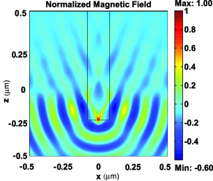
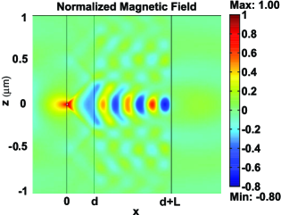
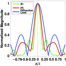
One way to demonstrate an optical leaky waveguide with anisotropic metamaterials with enhanced local radiation effects based on use of a metal-insulator stack is to embed the slab in a dielectric host with large permittivity . In Fig. 2LABEL:sub@fig:SiO2.Ag_563.6nm, we investigate the homogenized Ag/ metal-insulator stack embedded in a silicon (Si) host as a possible realization of an anisotropic leaky waveguide. The finite element simulation result clearly demonstrates that the slab behaves as an optical leaky waveguide radiating backwards, due to the signs of the effective and , and the dominant is obtained as . Since the leaky mode supported by the system can have , a planar near-field imaging system that transfers sub-diffraction features can be envisioned by pairing a backward leaky waveguide with a silicon slab, as shown in Figs. 2LABEL:sub@fig:SiO2.Ag_563.6nm_Focusing and 2LABEL:sub@fig:SiO2.Ag_LensImage. As illustrated in Fig. 2LABEL:sub@fig:SiO2.Ag_563.6nm_Focusing, the waves radiated from the source emerge as strongly confined beams inside the anisotropic slab, with a direction given by the resonance cone angle , and then re-radiate into the backward quadrant at the interface between the anisotropic waveguide and the silicon slab to form a focal point at a certain distance from the interface. Figure 2LABEL:sub@fig:SiO2.Ag_LensImage shows the normalized amplitudes of magnetic and electric fields at the image plane. The fundamental difference between the present imaging system and the anisotropic bilayer lens [7] is that the bilayer lens preserves subwavelength information through continuous spectra, whereas the present system employs only a discrete number of leaky modes to accomplish resolution enhancement.
References
- [1] A. A. Oliner and D. R. Jackson, in Antenna Engineering Handbook, J. L. Volakis, ed. (McGraw-Hill, New York, 2007), 4th ed.
- [2] S. Enoch, G. Tayeb, P. Sabouroux, N. Guérin, and P. Vincent, Phys. Rev. Lett. 89, 213902 (2002).
- [3] P. Baccarelli, P. Burghignoli, F. Frezza, A. Galli, P. Lampariello, G. Lovat, and S. Paulotto, IEEE Trans. Microwave Theory Tech. 53, 32 (2005).
- [4] A. Alù, F. Bilotti, N. Engheta, and L. Vegni, IEEE Trans. Antennas Propag. 55, 882 (2007).
- [5] C. Caloz and T. Itoh, Electromagnetic Metamaterials: Transmission Line Theory and Microwave Applications (Wiley, New York, 2005).
- [6] D. R. Smith and D. Schurig, Phys. Rev. Lett. 90, 077405 (2003).
- [7] H. Liu, Shivanand, and K. J. Webb, Opt. Lett. 34, 2243 (2009).
- [8] N. Engheta, Science 317, 1698 (2007).
- [9] V. A. Podolskiy and E. E. Narimanov, Phys. Rev. B 71, 201101 (2005).
- [10] E. D. Palik, ed., Handbook of Optical Constants of Solids (Academic Press, New York, 1998).