Corresponding author e-mail:]pmellado@seas.harvard.edu Current address:] School of Engineering and Applied Sciences, Harvard University, Cambridge, Massachusetts 02138, USA Current address:] Sandia National Laboratories, Albuquerque, New Mexico 87185, USA. Current address:] School of Engineering and Applied Sciences, Harvard University, Cambridge, Massachusetts 02138, USA
Mechanical response of a self-avoiding membrane: fold collisions and the birth of conical singularities
Abstract
An elastic membrane that is forced to reside in a container smaller than its natural size will deform and, upon further volume reduction, eventually crumple. The crumpled state is characterized by the localization of energy in a complex network of highly deformed crescent-like regions joined by line ridges. In this article we study, through a combination of experiments, numerical simulations, and analytic approach, the emergence of localized regions of high stretching when a self-avoiding membrane is subject to a severe geometrical constraint. Based on our experimental observations and numerical results, we suggest that at moderate packing fraction, inter-layer interactions produce a response equivalent to that of a thicker membrane that has the shape of the deformed one. We find that new conical dislocations, coined satellite d-cones, appear as the deformed membrane further compactifies. When these satellite d-cones are born, a substantial relaxation of the mechanical response of the membrane is observed. Evidence is found that friction plays a key role in stabilizing the folded structures.
pacs:
46.70.-p,62.20.-x,46.32.+x,46.15.-xI Introduction


When an elastic membrane is constrained into a small volume, the initially flat structure experiences Euler buckling Landau and Lifshitz (1995); Concha et al. (2007). As the accessible volume decreases, the membrane goes through a second transition generating a region where the strain localizes and a crescent singularity is born. This new configuration minimizes the total energy at the expense of the emergence of this pivot point. Beyond the crescent, the membrane forms a structure known as developable-cone (d-cone) Amar and Pomeau (1997); Cerda and Mahadevan (1998); Chaïeb et al. (1998); Cerda et al. (1999). Subsequently, as the available space is further reduced, complex patterns appear, ridges that join these localized objects forming a network in which energy localizes Lobkovsky et al. (1995); Lobkovsky (1996); Kramer and Witten (1997); DiDonna (2002); Vliegenthart and Gompper (2006); Witten (2007).
Besides bending and stretching, connectivity and self-avoidance are also key ingredients in crumpling Vliegenthart and Gompper (2006); Tchernyshyov and Sondhi (2002), both determining the evolution and the final fate of the folding process. On the one hand, the connectivity of a sheet forces the emergence of the above-mentioned network of highly stretched regions when volume restrictions are imposed. On the other, self-avoidance plays a key role in the mechanical response of the crushed membrane since perfectly elastic membranes that incorporate excluded volume energy are much stiffer than phantom ones Vliegenthart and Gompper (2006). This suggests that it may be possible to rationalize a self-avoiding membrane as one effectively thicker than its phantom version.
In this paper, we study a model system that allows us to make a natural link between the folding mechanism and the birth of new crescent singularities. The experimental setup consists of a circular membrane of radius , that under the action of a point-like traction load directed along the vertical direction, is forced to pass through a hole of radius . The plane of the hole divides the space into two domains and , as shown in Fig.1. We find that the mechanical response (force versus displacement plot, -, see Fig.3) exhibits a series of hardening-softening events as well as catastrophic events at large confinement. A direct relation between the emergence of these prominent non-linearities, the frictional collision of folds, and the birth of new singularities is reported and discussed.
The paper is organized as follows. Section II is a description of the experimental methods and results are reported in Section III. Section IV is devoted to numerical simulations as well as to the analytical results valid in certain regimes of the force versus displacement curve. Finally, Section V contains concluding remarks.
II Measurement of the mechanical response
The membranes used in all our experiments are made of acetate. Their thickness is mm and their radius mm. Their bending stiffness was obtained by measuring the slope at the early stage of the experimental mechanical response curve of the membrane shown in Fig.3, N m (details of the scaling in this stage are presented in Section IV). We performed a tensile test (using the Instron 5544 system) to determine the Young modulus of the membranes, N/. The Poisson ratio , was then computed using the formula . The radius of the hole is fixed at mm.
To pull a membrane by its center, we punched a small hole at the center with a surgical needle and put a thin, stiff wire through the hole. At one end of the wire we attached a copper ball of diameter mm. Then, the wire was pulled in order to produce a contact region between the copper ball and the membrane. Afterward we painted that region with a small amount of silicone glue to restore the membrane connectivity. We connected the free end of the wire to a commercial digital dynamometer (UltraSport) and a home-made system of screws that allowed a controlled displacement in the vertical direction and the simultaneous measurement of the reaction force exerted by the membrane. Special care was taken to make the size of the perturbed region much smaller than the typical size of the core of the elastic singularity, which for the present case was mm. We pulled the membrane down in the vertical direction , at a rate of mm/s, a factor slower than in a previous work Boue et al. (2006). This is an important point since the mechanical response depends on how fast the membrane is pulled because of friction. This dependence becomes stronger when folds collide. In all experiments the vertical displacement of the tip of the membrane was measured directly with a digital micrometer Mitutoyo. We observed that each time the membrane was pulled a distance , it took at least seconds for the sliding process to stop. For this reason, every time we pulled the membrane, we waited approximately seconds until the sheets had completely relaxed. This interval was long enough for the reaction force measured by the dynamometer to reach a constant value, confirming that the sheet had reached a stationary state. As the membrane progressed along the vertical direction, it was more difficult to pull it and the force needed to drag it down became larger and larger. But this process was non-monotonic: every time two folds collide and slide over each other, or a catastrophic event such as when a satellite d-cone is born, the force needed to pull and hold the membrane drops dramatically, indicating an instability of the packing structure of the membrane.
To obtain data with reliable statistics, we repeated each experiment times (and each time we used a new membrane of the same physical characteristics as described above). We studied regular, lubricated, and sticky membranes in order to examine the role played by friction. To obtain membranes with different friction coefficients but the same mechanical properties, we coated the regular acetate membranes. The reduced friction case was realized by applying a thin layer of graphite powder. We applied the graphite with a clean brush and remove the loose powder. In the opposite limit, to increase the friction we applied a thin film of spray glue, minutes before the experiment was started. For obtaining as uniform as possible films, we sprayed the glue to the samples from 1 meter apart during 5 seconds. The change in the thickness of the samples due to the glue coating was measured using a micrometer, being in average of percent. The change in thickness due to the graphite powder was negligible. The results of the tensile tests (performed with the Instron 5544 system) applied to the coated membranes yielded a change of the Young’s modulus due to the coating of percent. The change in the bending stiffness was negligible as well, as apparent from Fig.3. The mechanical response for these membranes are shown in Fig.3 with error bars deduced from variations of the experimental data on repeated runs.
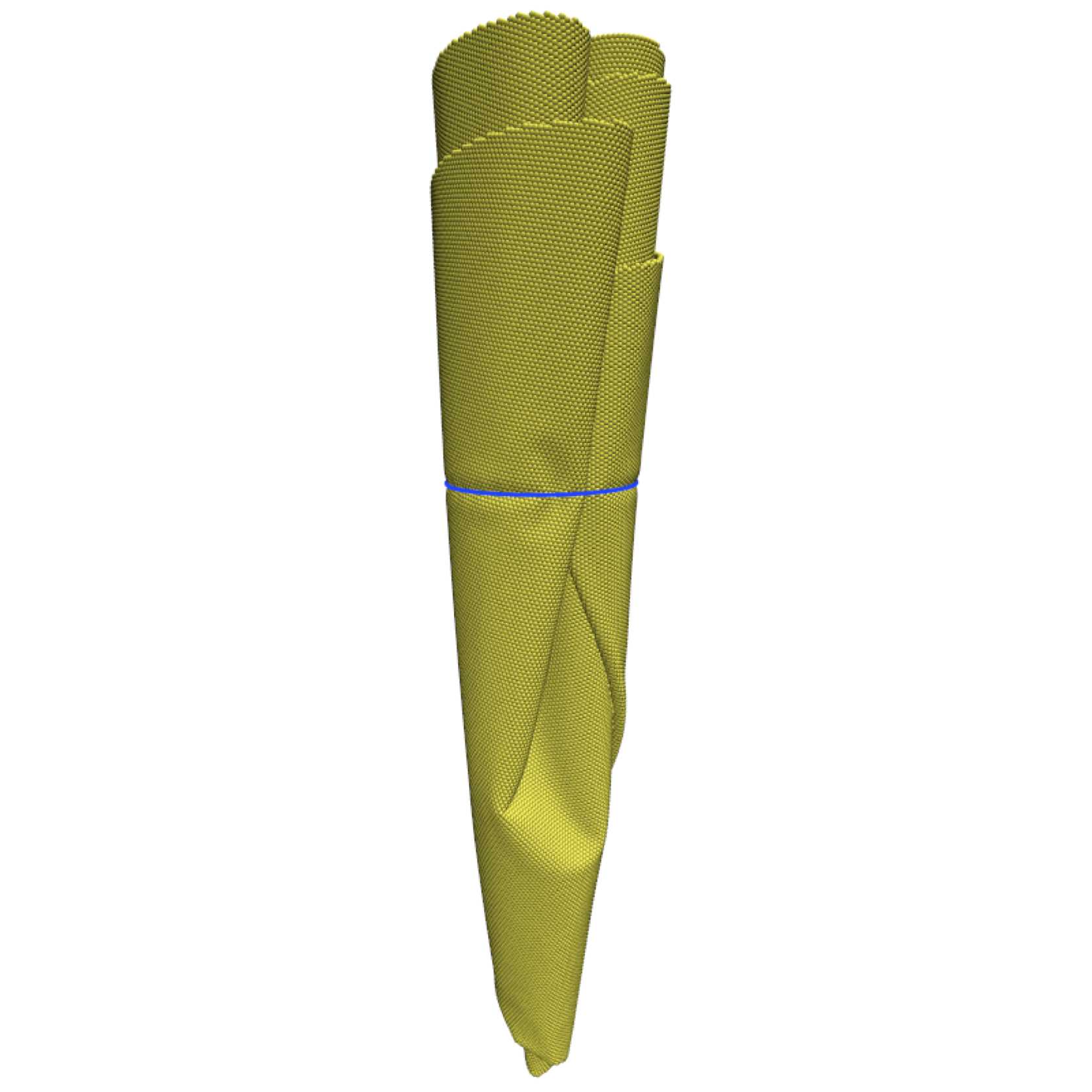
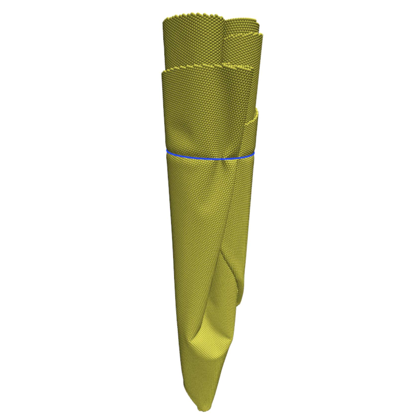
To examine the deformations that appear when an already compacted structure with conical symmetry is pulled, we performed a similar experiment with membranes whose initial geometry is conical, Fig.2. Each cone was cut out of a circular membrane with a deficit angle of .

We glued opposite sides of the cut with epoxy and used a hair dryer to release internal tensions in the material. We repeated each experiment times as well for the same deficit angle. We did observe that a d-cone never appeared on the suture line most because along the suture the bending stiffness is larger than in the rest of the structure. The mechanical response is shown in Fig.4. A more detailed description of the geometry and evolution of these deformations will be presented elsewhere Concha et al. (to be published).
III Experimental Results
III.1 Compaction of the membrane
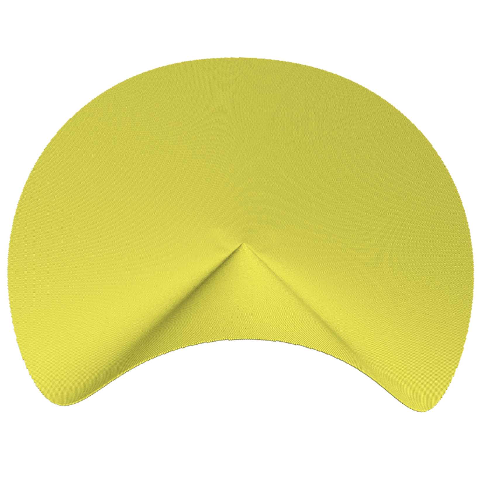
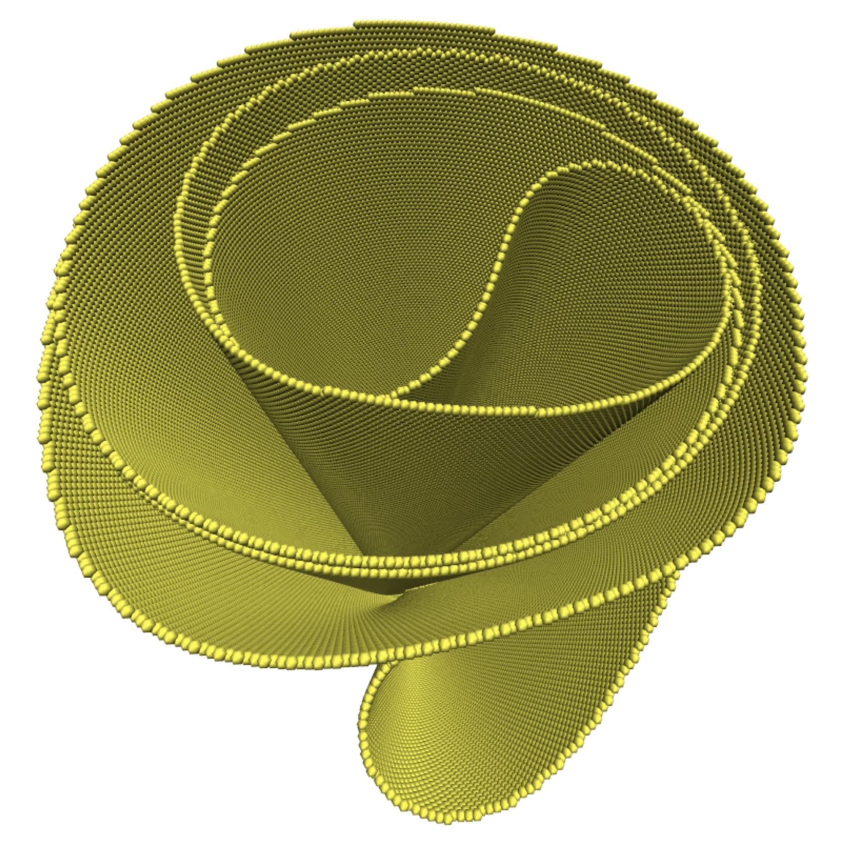
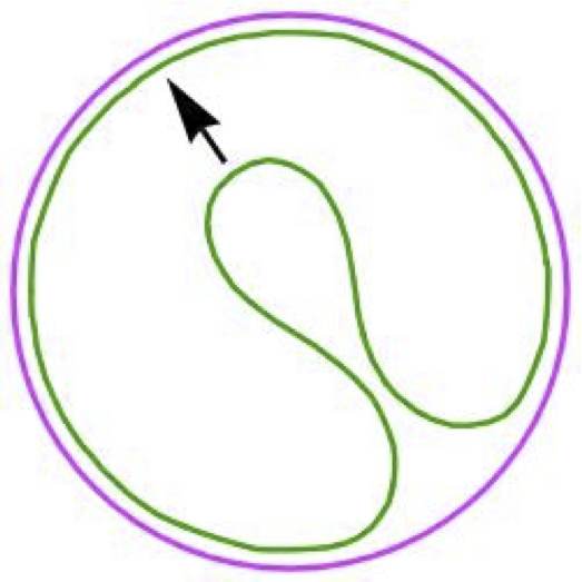
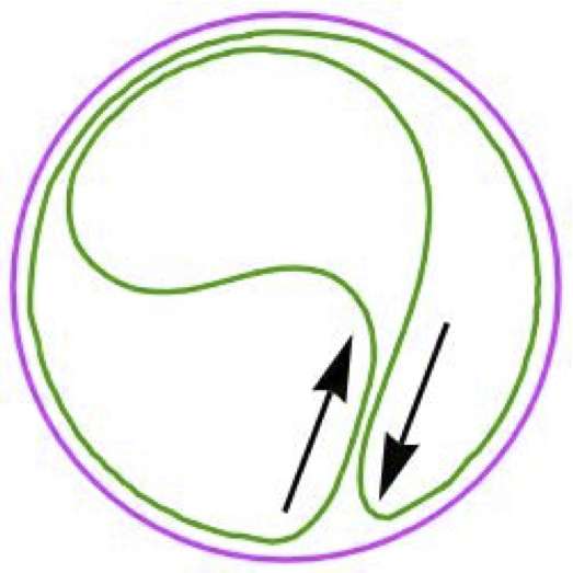
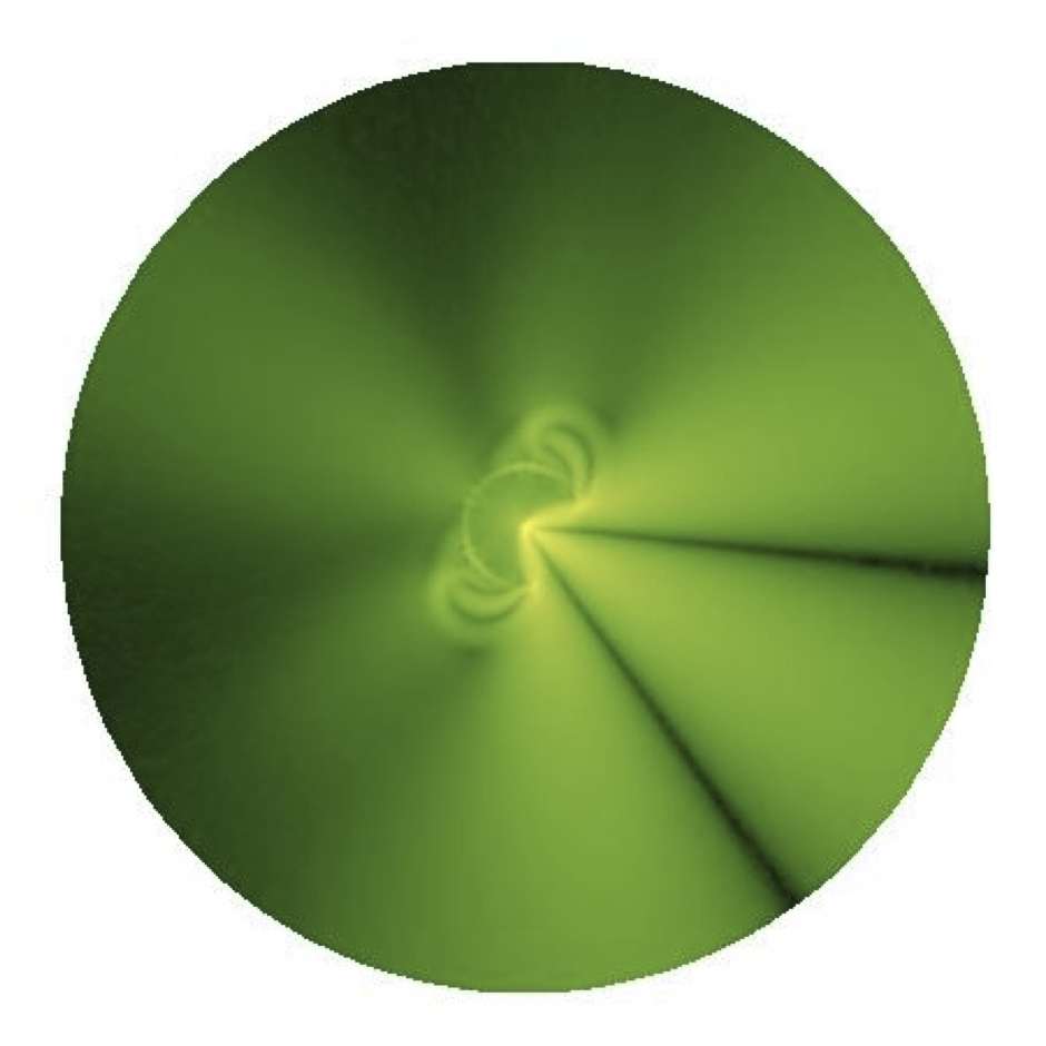
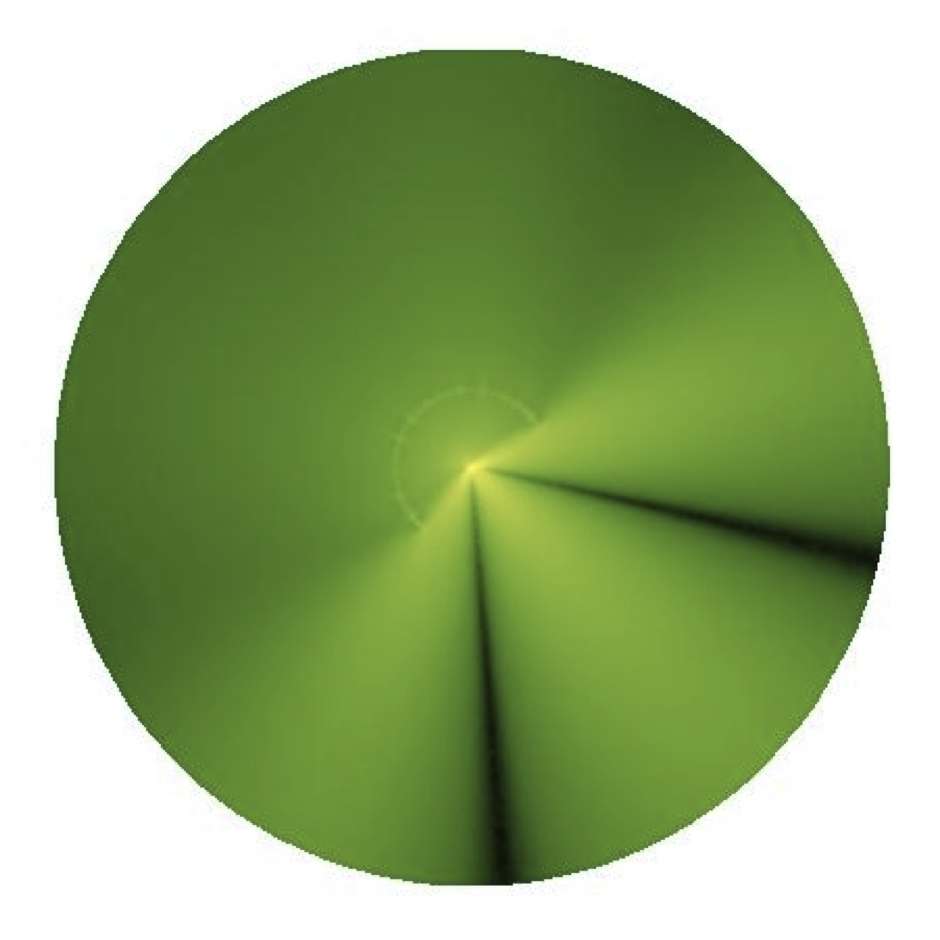
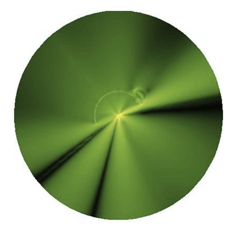
Experimentally we found three qualitatively different regimes of the mechanical response of the membrane. During the initial stage the membrane deforms elastically until the pulling force reaches a critical value at which the first d-cone singularity appears Cerda et al. (1999); Cerda and Mahadevan (1998). As we keep pulling, the single-valued description used in previous work Cerda and Mahadevan (1998) breaks down. The d-cone structure evolves until it touches itself, producing a contact interaction between the two opposite radial lines of the membrane due to self avoidance. This new structure is stiffer and, if observed from the top (See Fig.1b), contains three regions separated by the contact lines. The first contact between the two folds marks the end of the first regime and the birth of the second and occurs for mm (shown in Fig.3 and Fig.1b). Once in the second regime, the frictional interaction of two folds at mm, produces a large mechanical response as denoted in Fig.3 by the leftmost (blue) arrow.
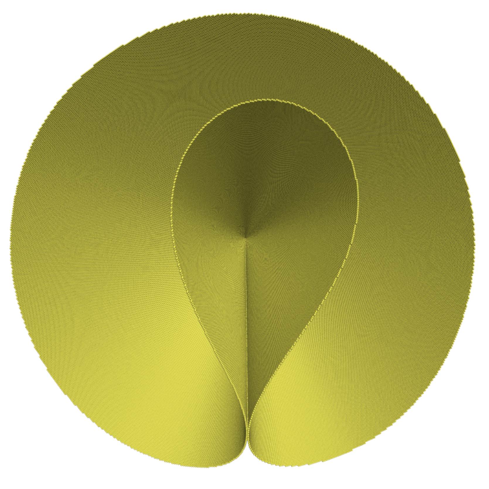
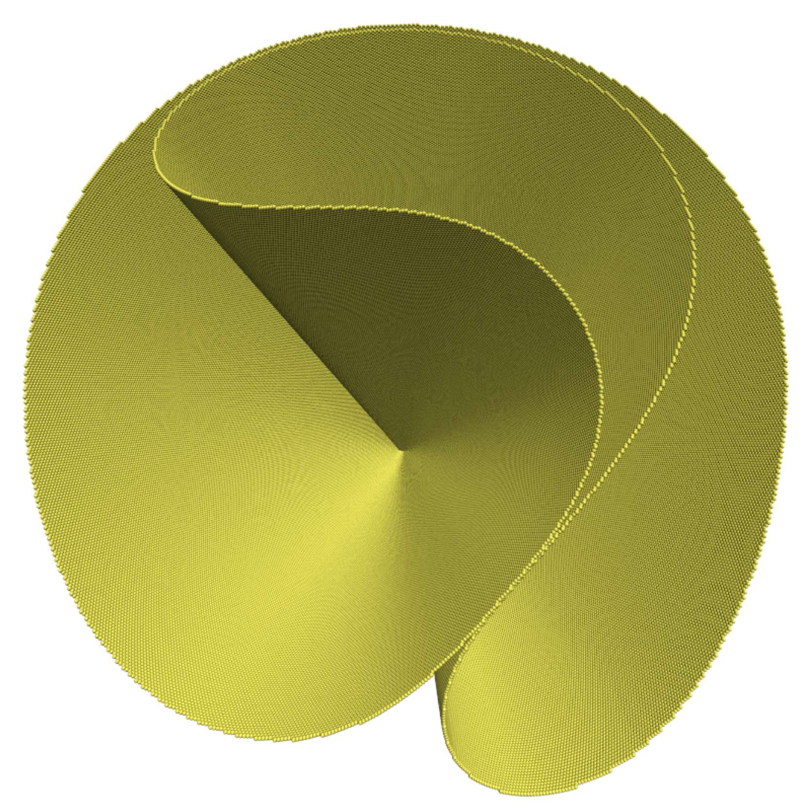
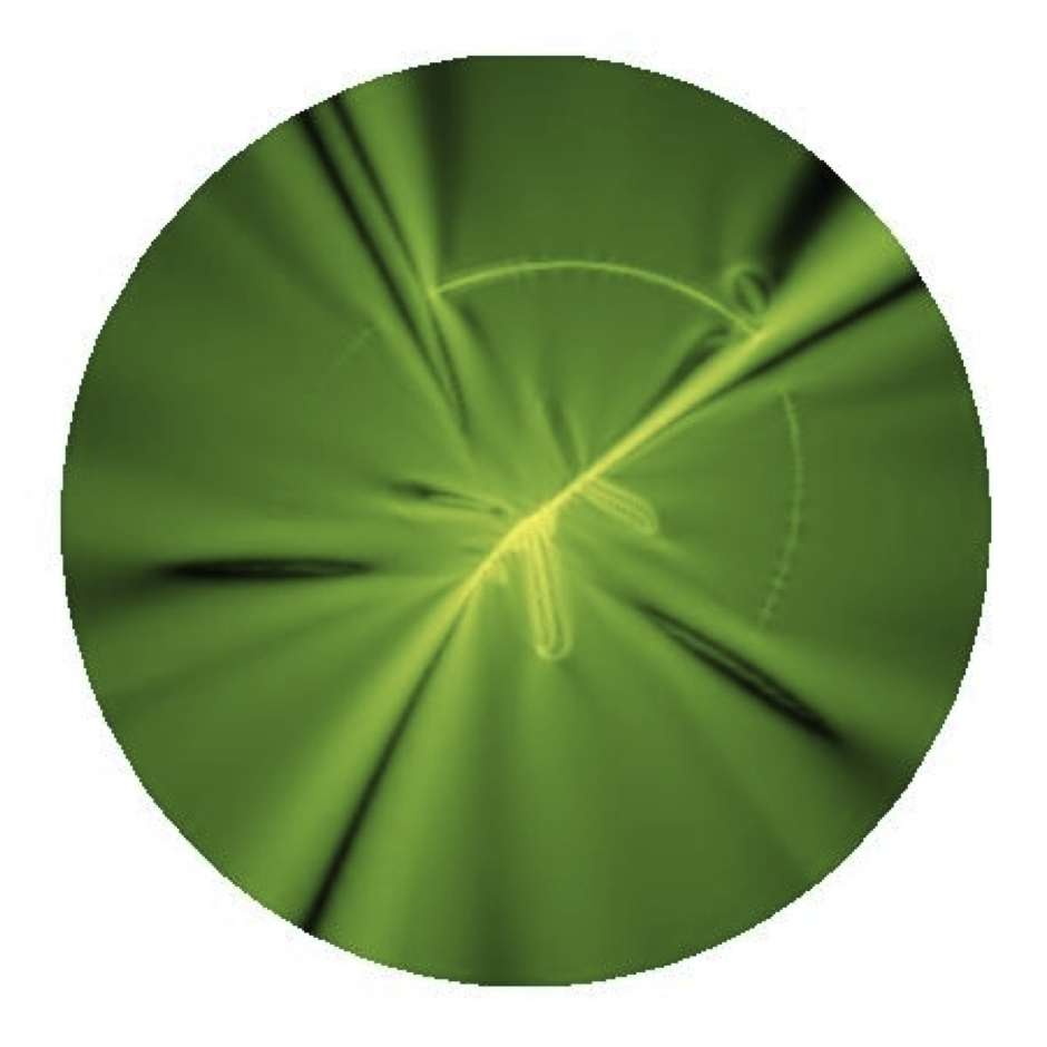
As the vertical displacement is increased at a constant rate beyond mm, the main central fold shown in Fig.1b is pushed against the opposite side of the membrane and eventually slops when friction of the two external folds can not stabilize the system any longer. After that, a main spiral develops and breaks the mirror symmetry of a simple d-cone. The break of mirror symmetry is the signature of the second regime (see Fig.1c). However, in this process the translational symmetry along the conical generator is still preserved, particularly outside the core region near the membrane tip. As we keep pulling along , more folds are produced and forced to touch each other, the whole sheet becomes highly rigid, and due to self avoidance, it eventually shows an enhanced mechanical response, a peak signaling the fact that the membrane is stuck. At this point, if we increase the load further, a catastrophic event will occur: the formation of what we dubbed a satellite d-cone that breaks the local translational symmetry along the conical generators, as shown in Fig.1(d) and Fig.2(d). This event is characterized by a sudden drop in the force-displacement curve, indicated by the middle and rightmost (black) arrows in Fig.3 ( depends on friction, mm for sticky membranes for regular membranes) which marks the end of the second regime and the onset of the third one. The rearrangement of folds allows the system to keep evolving into more compact states as the membrane is being pulled along . We emphasize that the breaking of the translational symmetry along the conical generators makes this effect intrinsically three dimensional, and any attempt to model this softening with a two dimensional model is doomed to fail. Indeed, a study based on a two-dimensional description Boue et al. (2006) suggested that at large compactations divergent mechanical responses are expected.
The emergence of a satellite d-cone is the striking signature of the third regime. This is the simplest realization of an energy cascade proposed as the soul of crumpling a long time ago and a beautiful example of a nested generation of energy condensation Cerda et al. (1999); Witten (2007).
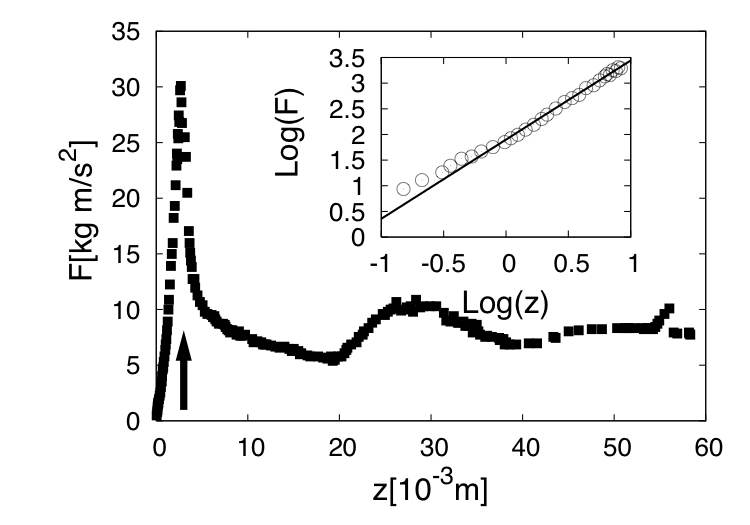
The three curves shown in Fig.3 clearly show that friction does play an important role in the mechanical response of our system.
Friction in two dimensional packing of wires was shown to have a strong impact in the packing morphology Stoop et al. (2008), showing the so-called classical, spiral, and plastic morphologies. However, in two dimensions crumpled wires do not have the freedom to release energy by deforming into another dimension as in the case discussed here. In two dimensional systems, a divergent mechanical response close to a non-universal (material-dependent) critical packing ratio is generically observed, which for certain parameters was found to be Stoop et al. (2008). Our case is different and does have a third dimension that allows new deformation modes. One example is the satellite d-cone observed here. We further found that the vertical displacement at which the satellite d-cone forms depends on friction. The middle and rightmost (black) arrows in Fig.3 indicate that the satellite d-cone appears earlier when the friction is larger. This can be qualitatively understood in the following way: larger friction means it is harder for touching layers to slide over each other, which makes the membrane effectively more rigid. Therefore, for membranes with a larger friction coefficient, the compaction preserving the translational symmetry along the conical direction stops at smaller vertical displacements. As the displacement is further increased, the satellite d-cone appears to allow the membrane to further compact.
All our experimental and simulation results indicate that the satellite d-cone is the basic deformation mechanism of a conical surface, which is effectively the geometry of the flat membrane when it is in a compacted state with translational symmetry. To provide more evidence of this statement, we performed an experiment of a membrane whose initial geometry was conical. This experiment (see Figs.2-4) shows that for large confinement, once the folded membrane is stuck at a certain friction dependent position, the system starts to stretch until it reaches a critical force at which energy focuses in a localized region. This region is at a certain distance away from the membrane tip and is the core of the satellite d-cone.
The mechanical response of the cone is shown in Fig.4. The first stage is characterized by a dragging force that grows as a power law , where , as obtained from the best fit of the curve shown in the inset of Fig.4. In this regime the overall symmetry of the cone remains unchanged, therefore the measured force can only be due to the stretching of the membrane. After a critical load has been reached, or equivalently, after a critical amount of energy has been stored in the stretching mode, the conical shape becomes unstable and a satellite d-cone is born, as shown in Fig.2b and as indicated by the arrow in Fig.4. The energy transfer between stretching and bending modes is reflected in the - curve as a sudden drop in , similar to what is observed in Fig.3 for a flat membrane in a compacted state. After the satellite d-cone is formed, the system evolves in a similar way to the evolution of the initially flat membrane at intermediate packing fraction. In this regime the - curve goes down until opposite sides of the cone touch each other.
III.2 The role of friction
Fig.3 shows that at small vertical displacements, friction and self-avoidance play no role because different parts of the membrane do not touch yet. In this region, all membranes with different frictional treatments exhibit the same mechanical response and the force-displacement curves collapse. However, we do not anticipate any possible collapse of the - curves beyond the first fold collision. In this region, the different friction properties of the membranes affect the collision and sliding of folds, leading to friction-dependent mechanical responses, like the non-universal behavior found in the compactation of wires in 2D Stoop et al. (2008).
Generally, for larger friction wider folds are observed before they slip. This observation allowed us to further unveil the role of friction quantitatively. We estimated its contribution by computing the friction coefficient in two ways. In the first approach we analyzed a fold collision at low packing fraction (which is representative of the processes happening at more compact configurations). An example is shown in Fig.1b, where two folds touch each other. This state will last as long as the forces in the direction perpendicular to the contact line do not overcome the frictional forces. As the pushing force increases due to increasing confinement, both folds become wider and eventually buckle as if they were a single rod, forming an effective Euler elastica (see schematic representation shown in the inset of Fig.3). At this stage the contact point will work as a joint and the folds will move with respect to each other: the reaction force will increase until they slip. We make use of this description to estimate the stability of the collision of two folds in the experiment. The only force stabilizing the system is friction, , in which is the static coefficient of friction and is the normal force. By virtually cutting an Euler elastica into two halves, we compute the bending force needed to keep the system together with the virtual work technique. Equating these two forces yields
| (1) |
where is the size of the effective rod, , its Poisson ratio, and is the displacement of the edges of the rod from its initial position along the boundary. Experimentally we found . Thus can be estimated using Eq.1. In the second approach, we obtained using a traditional method: An incline and a block that is free to slide as soon as the incline reaches a critical angle . The friction coefficient in this case is well known to be given by
| (2) |
The coefficients of friction obtained by these two independent methods agree well within experimental error . This indicates that the set of most prominent bumps observed in Fig.3, at low packing fraction are a consequence of the frictional collision between folds and that the height and position of these events in the - curve becomes material dependent since they are determined by friction.
In our experiments using membranes lubricated with graphite powder, the friction is very low and the onset of the satellite d-cone occurs for a larger load than in the case of the regular membranes. In other words, the satellite d-cone occurs later in the - curve. To study the opposite limit where friction is extremely large, we deposited a thin film of a 3M glue on top of the acetate membrane. This treatment makes the folds stick once they touch each other and they remain stuck unless the adhesive layer fails. But the failure never occurred in our experiments. In this extreme case, the membrane can only invaginate from the configuration in which the two main folds shown in Fig.1b are glued together. We discovered that the effect of this strong attractive contact interaction is to produce a cone like the one shown in Fig.1c earlier than for the regular membranes. Consequently, the onset of the satellite d-cone occurs earlier in the - curve (see middle (black) arrow in Fig.3).
IV Molecular Dynamics Simulations
| 1 | 2 | 3 | 4 | 5 | 6 |
|---|---|---|---|---|---|
a
|
|
|
|
|
|
b
|
|
|

|

|

|
c
|
|
|
|
|
|
d
|
|
|
|
|
|
e

|
|
|
|
|
|
To understand the compaction of the membrane in more detail, we modeled a membrane dragged through a small hole using molecular dynamics (MD) simulations. This allows us to explore and analyze not only the mechanical response of the membrane, but also its energetics and compacted geometry.
We used the computational model of an elastic sheet constructed by Seung and Nelson Seung and Nelson (1988). The sheet was modeled as a triangular lattice with neighboring vertices bonded by springs. The harmonic potential of each bond is
| (3) |
where is the spring constant and the equilibrium bond length. We express all simulation parameters and results in terms of the Lennard-Jones (LJ) units based on the LJ potential defined as
| (4) |
where and are the characteristic bending energy and length. Their units are denoted as and , respectively. LJ units are based on , , and the mass of the vertices. For example, the unit of time is . For the bond potential in Eq. 3 we used and . The bending energy of the sheet is given by
| (5) |
where is the characteristic energy of bending and is the dihedral angle between two adjacent triangles that share a bond. For simulations reported here, . From and , one can derive the stretching and bending moduli of the sheet by identifying the low energy limit of this lattice modelSeung and Nelson (1988). In our case the bending modulus is and the 2-D Young’s modulus . The equivalent sheet thickness is given by .
The self-avoidance of the sheet is imposed by adding an extra interaction between all non-bonded vertices. This interaction is described by an LJ potential with and . The potential is truncated at to make it purely repulsive. The same potential is used to impose the interaction between the sheet and the confining hole. The later is implemented as a ring of vertices uniformly distributed on a circle with radius and spacing .
The MD simulations were performed using the Large-scale AtomicMolecular Massively Parallel Simulator (LAMMPS) developed at Sandia National Laboratories. A velocity-Verlet algorithm with a time step was used to integrate the equations of motion. We performed two types of simulations. In one, a gradually increasing force was applied to the tip (the central vertex) of the sheet to pull it through the hole. At a given force, MD was run for a certain period (usually ) and then an energy minimization based on the Polak-Ribiere version of the conjugate gradient algorithm was performed. In this type of simulation, the energy of the sheet is minimized at each given force. In other simulations, the sheet was dragged through the hole by pulling its tip at a constant velocity along the vertical direction. The resistance force on the tip from the other part of the sheet was measured. We went to very low to reduce the inertial effect. In this case the measured force was found to be equal to the force exerted on the sheet by the confining hole within statistical errors. This indicate that the inertial effect is negligible.
The sheet is kept at a very low temperature through a Langevin thermostat. The Langevin damping rate is for low . For high , higher damping rates have to be used. Tests with different showed that results reported here are not sensitive to the damping as long as the inertial effect is negligible.
IV.1 Numerical Results
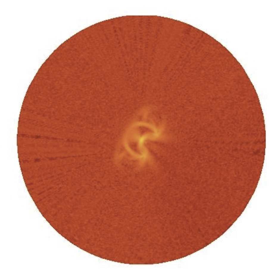
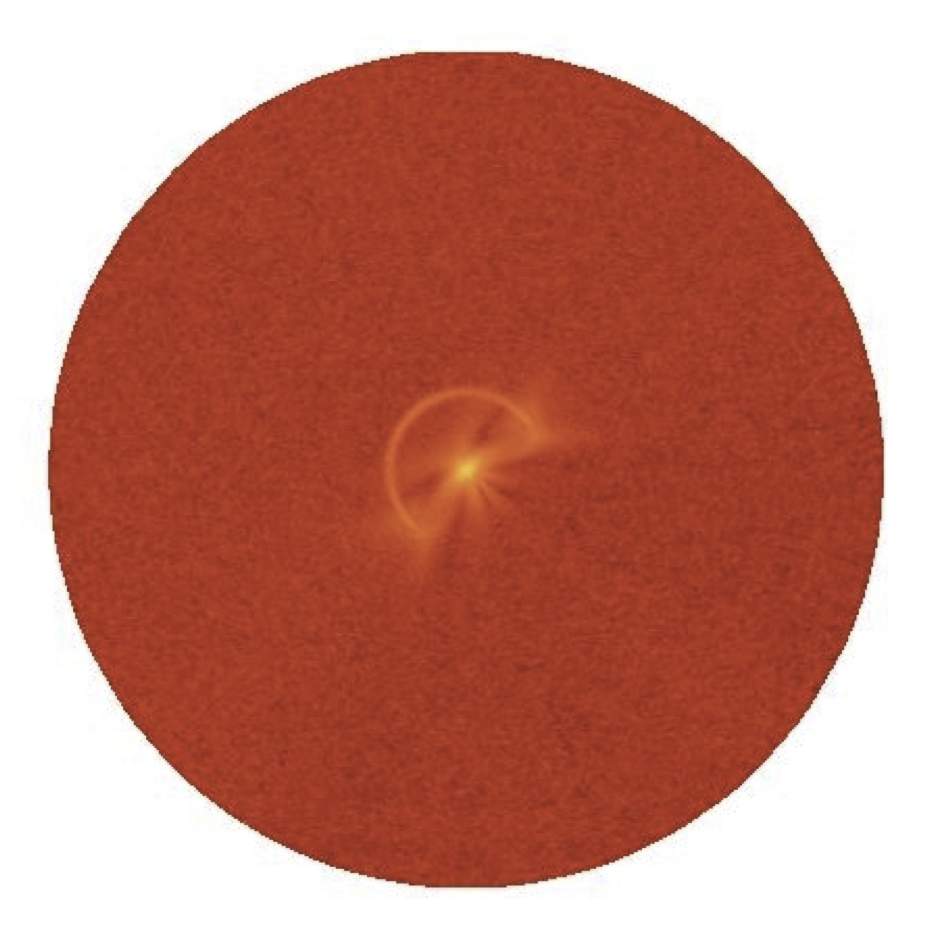
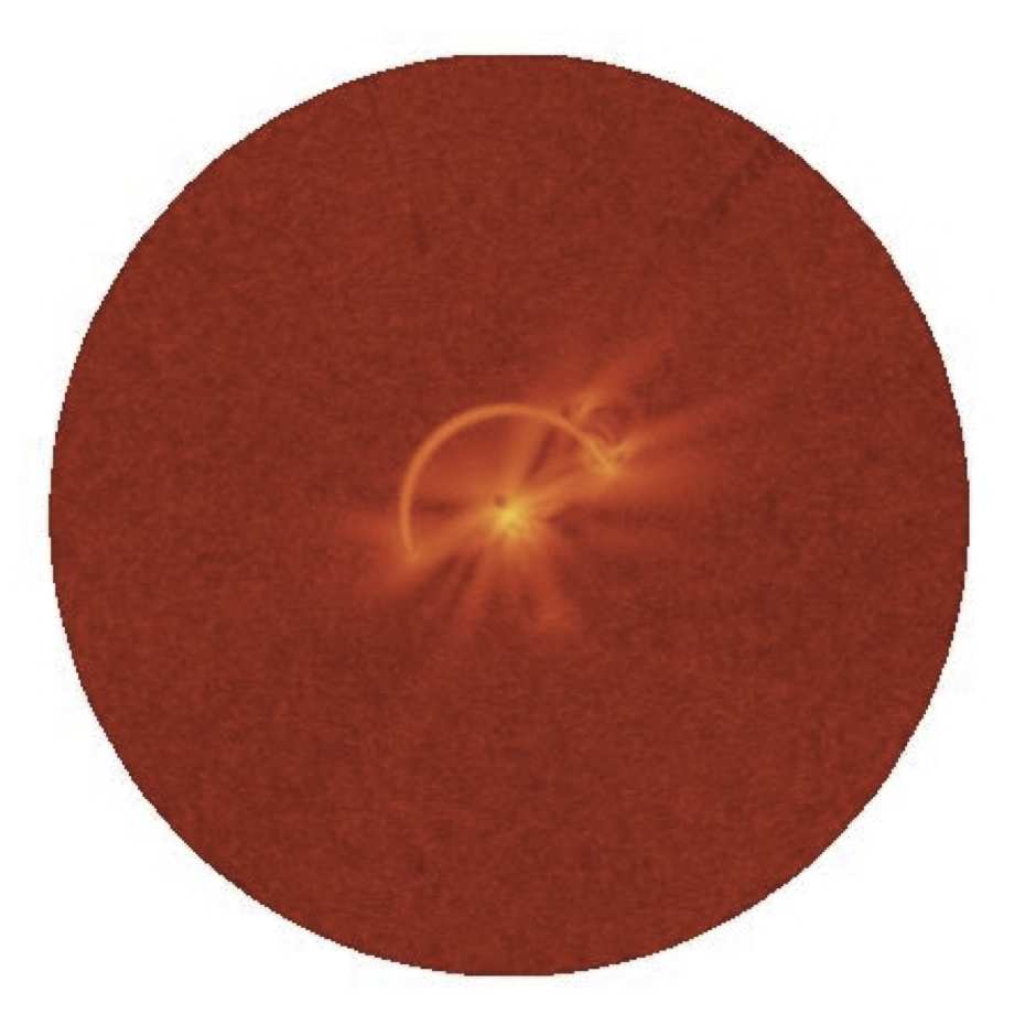
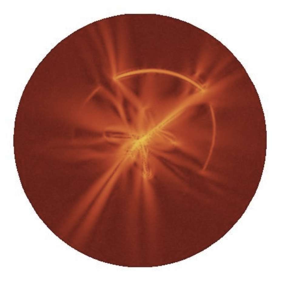
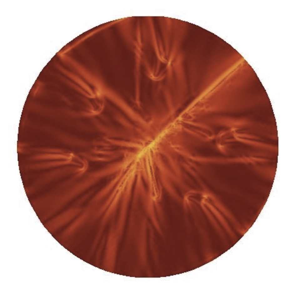
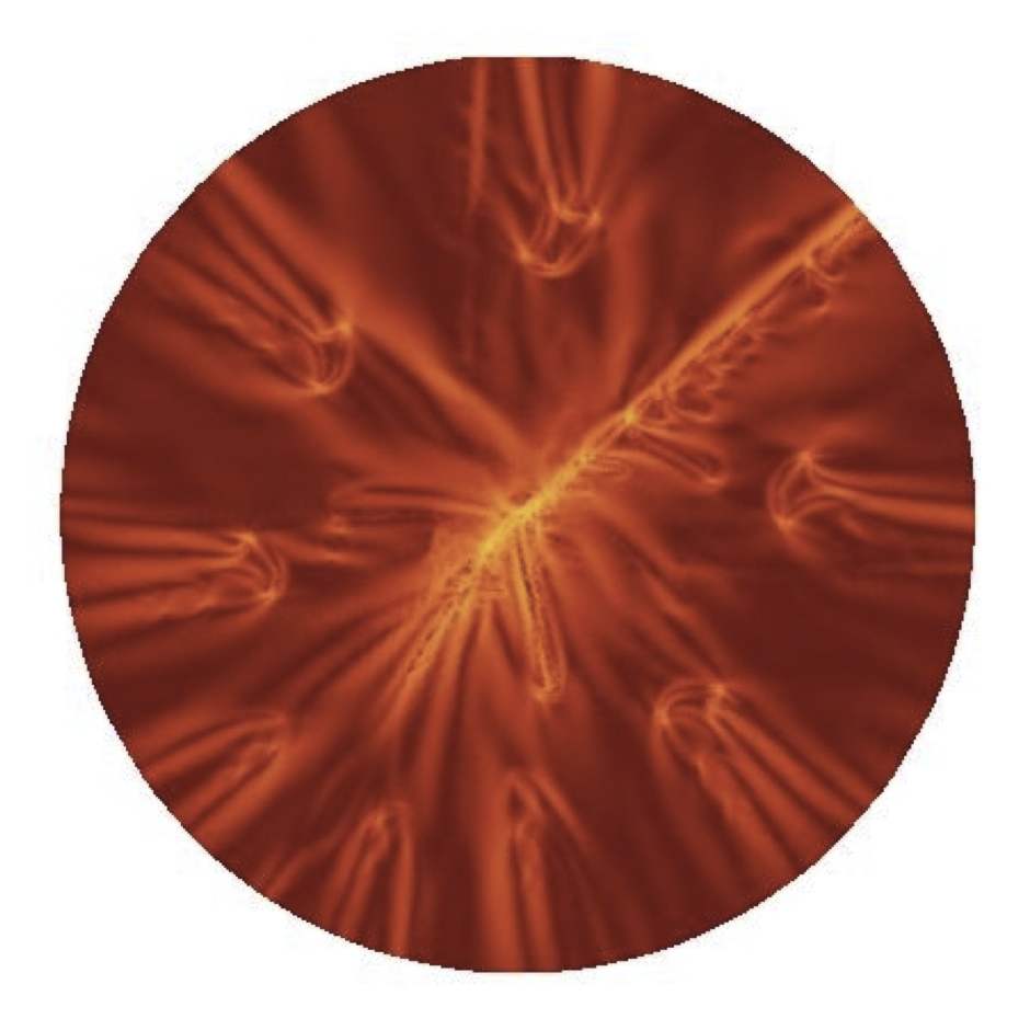
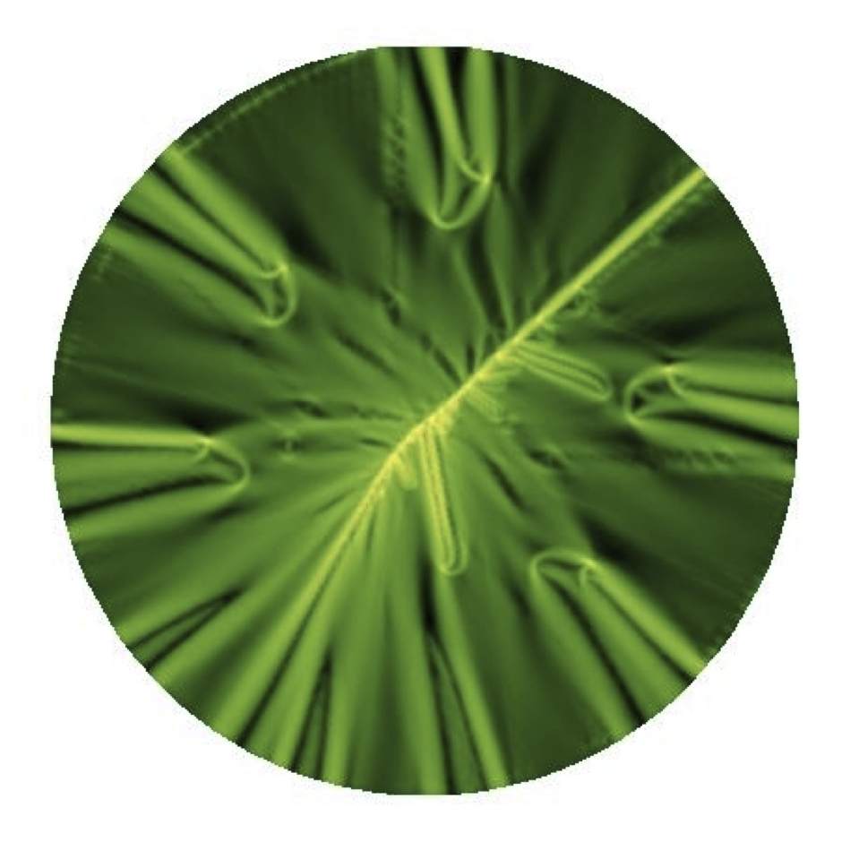
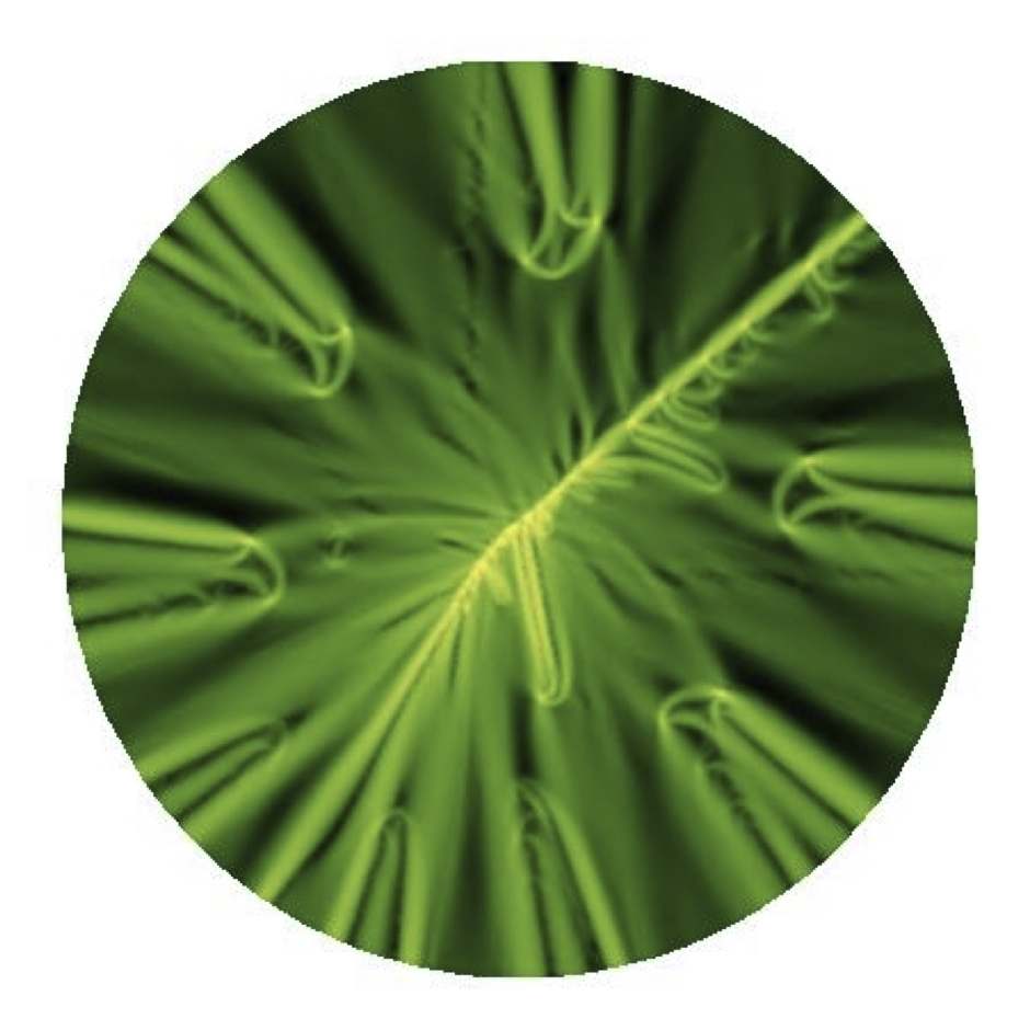
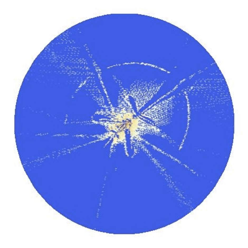
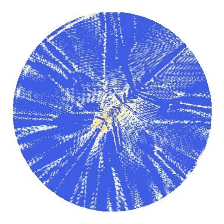
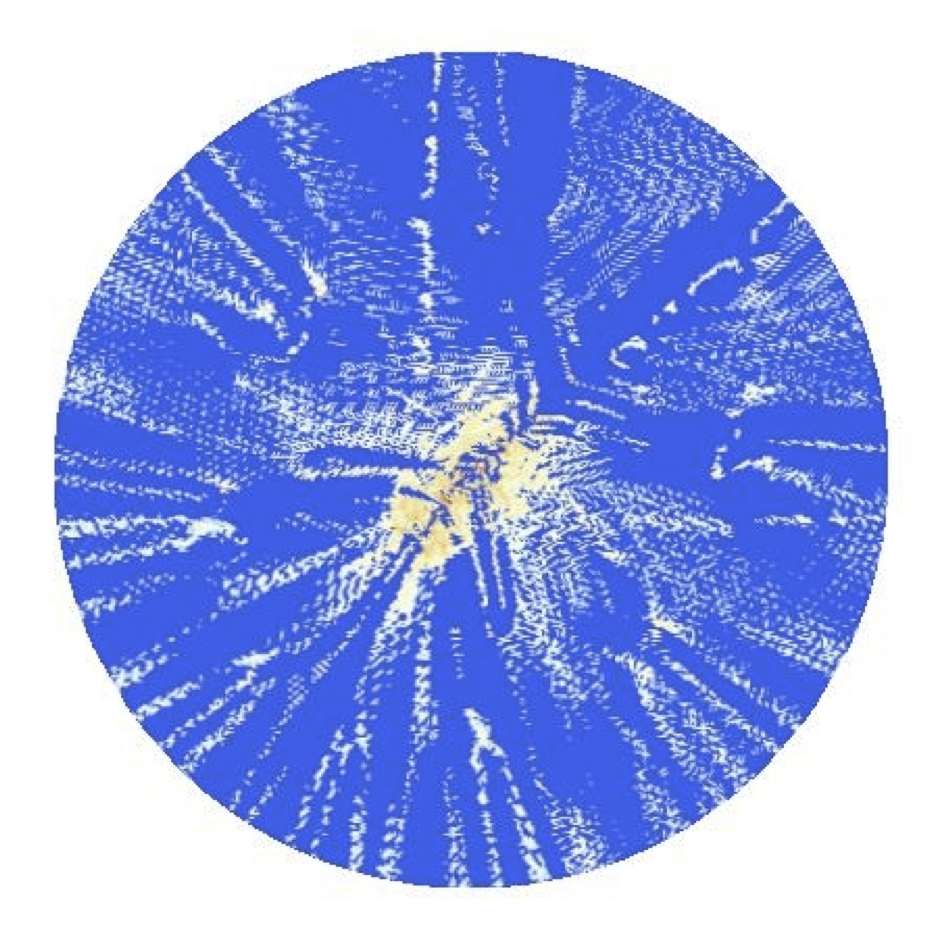
In Fig.5 we summarize the evolution of the geometry of an in-silico membrane that is being pulled through a hole. The results shown were obtained by pulling the central vertex of the sheet at a constant speed. The configurations of the membrane shown in row indicate that the model does capture all the regimes found in the experiments: The formation of the d-cone, collision of the main central fold, Fig.5 (a/2), and the subsequent formation of a spiral-like structure with folds touching and sliding. Finally the formation of the satellite d-cone is clear from Figs.5 ().
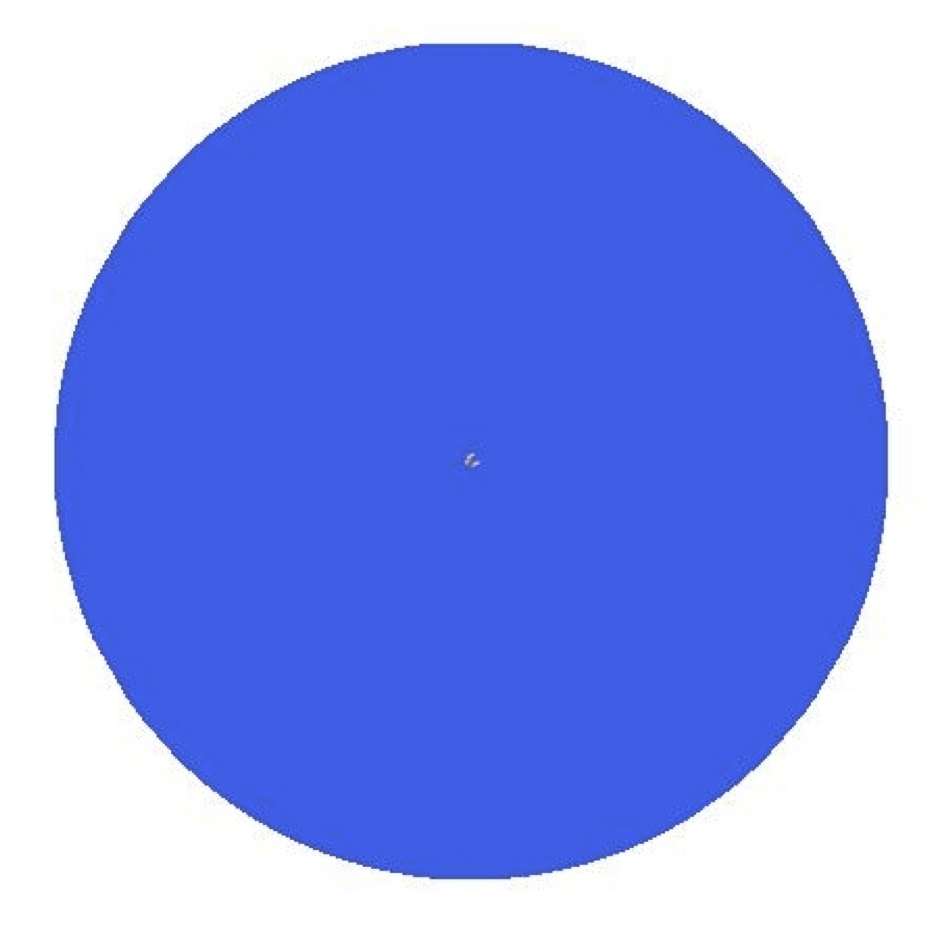
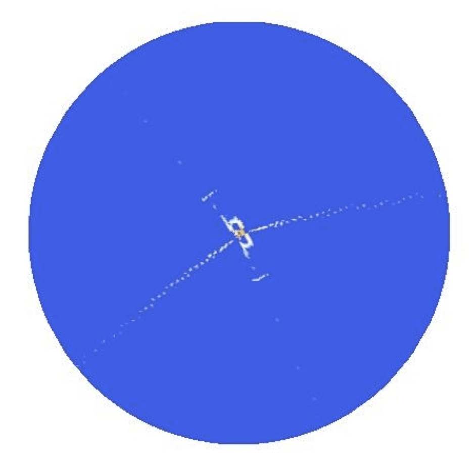
To qualitatively analyze how energy is transferred between different modes (bending, stretching, self-avoidance) we also show density plots of the different energy densities. It is clear from Fig.5 (c/4 and d/4) and Fig.5 (c/5 and d/5), that before the satellite d-cone is formed stretching concentrates around the tip and at the confining ring. After the satellite d-cone is formed, stretching goes down and the membrane folds. Energy is transferred from the stretching mode to the bending mode (see bright scars in Fig.5 (d/5). The results in Fig. 5 indicate that the distributions of the bending and stretching energies are very heterogeneous and they are strongly localized near the tip of the membrane, the apex of the satellite d-cone, and the ridges along which the membrane is bent when the packing ratio is very high.
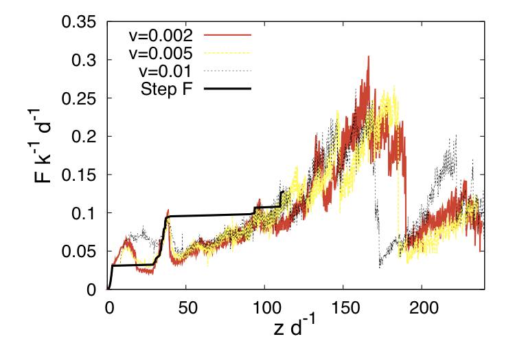
Overall, the mechanical responses of the in-silico membrane shown in Fig.6 are qualitatively similar to those observed in our experiments. The membrane initially deforms through stretching but the conical symmetry is preserved. The conical symmetry breaks down when the d-cone appears, though there is still a translational symmetry along the conical generators, at least outside the core of the d-cone. A slight drop in the dragging force accompanies the formation of the d-cone. Then the front of the d-cone moves inward and its two branches approach and collide. After this collision, the front of the d-cone keeps moving towards and finally collides with the opposite side of the membrane. After this point the two contacting branches of the d-cone start to flatten in response to the increasing confinement. At certain dragging force the two branches start to slide, inducing a clear drop in the measured dragging force on the membrane. This corresponds to the first major bump in the - curve. When the confinement is further increased, more branches and folds are born, collide, and slide over each other. Each sliding event accompanies a drop in F, appearing as a bump in the - curve. But overall F increases as the deformation grows. It should be emphasized that the translational symmetry along the conical generators is still preserved in this stage.
When the displacement of the membrane tip exceeds a certain amount, or equivalently when the confinement is strong enough, the translational symmetry breaks down with the appearance of a satellite d-cone. The apex of this second d-cone is away from the membrane tip. It appears in the form where many folds buckle and bend towards the interior of the compacted membrane. At this catastrophic event, the dragging force F drops dramatically by an order of magnitude, shown as a steep drop in the - curve. After this event, starts to increase again as the confinement is further increased.
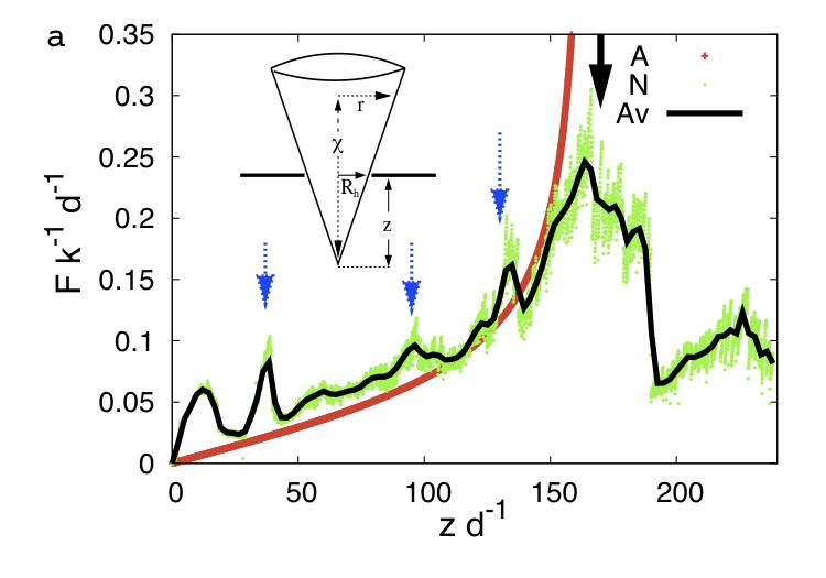
Though quantitative agreement is not expected, there is also an obvious qualitative difference in the mechanical responses of the membrane between numerical and experimental results. For example, in the second regime after the birth of the d-cone and the appearance of the satellite d-cone, more bumps in are observed in the numerical results (three bumps marked with three blue arrows in the simulations of Fig.7a, instead of the one observed in experiments). These bumps correspond to the consecutive collision and sliding of folds. The reason for this difference is that in-silico membranes are softer and less frictional. Fig.3 shows that the less frictional membrane, the one lubricated with graphite, shows more bumps than the others, closely resembling the numerical results. However, it should be emphasized that due to the roughness of the iso-potential lines that describe the surface of the in-silico membrane, there is an effective friction, even though we did not put any explicit friction law in the simulation. The effective friction is an analog of the tangential force that would appear when we try to slide two egg boxes that are on top of each other. Each atomic stick-slip process appears as a sudden bump in the - curve. This is also the reason that the numerical results are noisy, albeit quite reproducible for each dragging velocity.
Several experiments on crumpling were performed by compressing sheets with increasingly heavier weights Matan et al. (2002). In our set-up, this corresponds to applying a dragging force on the membrane that increases gradually. Results showed that this approach gives results different from those from experiments where the confinement or deformation of the sheet is controlled. It should be emphasized that experiments performed with increasing forces do not provide detailed information about the relaxation of the membrane, while such information is available from experiments performed with deformation controlled and mechanical response measured.
Simulations also allow us to vary the dragging force and measure the vertical displacement of the membrane tip. The latter is one signature of the mechanical response of the membrane. The solid (black) curve in Fig.6 shows one - curve generated in such a simulation. In the simulation the dragging force is increased in a stepwise manner. In most cases, the membrane reached a steady crumpled state quickly and was easily obtained. However, at certain values of , the membranes took a long time to relax. Typically, each relaxation corresponds to the transition from one locally stable compact configuration to another. For example, when the load reached the critical value at which the d-Cone appeared, and was kept at this point, the fold grew and moved towards the opposite side of the membrane, and its two branches approached each other. This process ends when the two branches touched and the front of the fold contacted the opposite side of the membrane. The membrane entered a new configuration, stabilized by the effective friction. This transition corresponds to the first plateau in the - curve as shown in Fig.6. Successive plateaus were observed at the occurrence of strong reorganization of folds, including the birth of new folds or abrupt interfacial sliding of contacting folds. The results here make it clear that the full - curve can only be obtained when , not , is controlled. The underlying reason is simply that is not a single-valued function of due to the hardening-softening of the membrane.
IV.2 D-cone formation
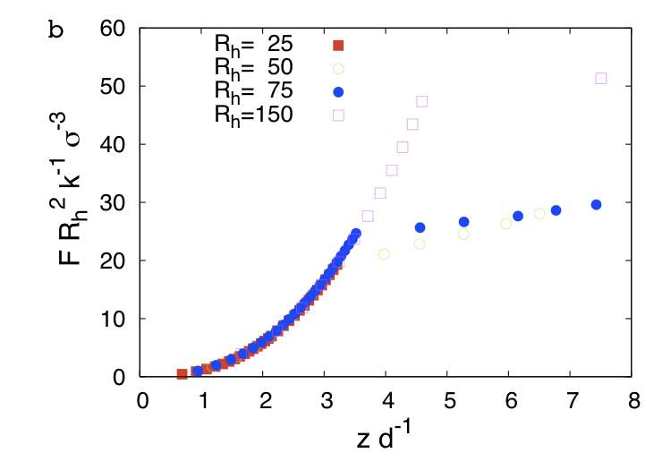
In real experiments it is extremely difficult to measure the initial deformation of the membrane. Intuition tells us that for any real membrane at low loads it should stretch, and then, once the stored energy is sufficient to produce a global change, a d-cone will be formed. This regime is readily explored for in-silico membranes. Results show that the - curve grows in a quasi-parabolic fashion, . This indicates that pure bending is not the relevant mode at extremely low loads. Otherwise, as predicted for a perfectly inextensible membrane Cerda et al. (1999).
In Fig.7b, the - curve at the early stage of the folding process is shown. Here numerical data for four different are plotted. Results show that the force has a universal functional form given by
| (6) |
This is a clear signature that at extremely low loads the membrane first stretches, and the d-cone only appears when a critical load is reached at . After the occurrence of the d-cone, the main energy contribution comes from the bending of the membrane, and the scaling shown in Eq.6 breaks down. This is seen from the discontinuity of the mechanical response at that marks the onset of the first d-cone. The correct scaling for the force just after the first d-cone is formed is well known, , where is the bending stiffness and mm is the core radius which is of the order of the crescent singularity. This scaling works for small deformations (small confinement) Cerda et al. (1999).
IV.3 Mechanical response at moderate packing.
We used a phenomenological route to explain - at moderate confinement after the first d-cone is formed and before the emergence of the satellite d-cone ( in Fig.7a) in terms of the bending energy of the system only. A similar approach was used by Boue et al. Boue et al. (2006).
We consider the bending energy in this regime as the sum of the bending energy of two regions that fold, qualitatively, in a different way (look at the inset of Fig.7a for clarity). The first contribution to the bending energy is from the isolated big fold living in the unoccupied core region. The second region contributing to the bending energy is the sector of the membrane far from the center of the cone.
The length of the enclosed inextensible membrane at the hole is:
| (7) |
determines the maximum polar angle:
| (8) |
Since the bending energy of the core region scales with the square of its curvature, we have that:
| (9) |
The characteristic radius for the fold living in the core region can be estimated as:
| (10) |
where is the polar radius of the cone at a vertical distance from the tip and is the thickness of the membrane. Placing this back into Eq.9 we get the final form for the bending energy of the core:
| (11) |
where R is the radius of the membrane and . In the limit when , the logarithmic contribution approaches . This simple model yields the signature of a divergent response when , evidencing that there is a critical distance at which becomes extremely expensive to deform the core region. The critical pulling distance is given by: which compares well with the numerical data ( see Fig.7a, black arrow).
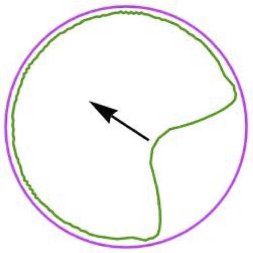
The second region is illustrated by the cross-section cut of the membrane shown in Fig.2. We model this region as an archimedian spiral. Its radius is
| (12) |
The bending energy from this spiral region is:
| (13) |
Finally, the total energy (approximated as the bending energy only) at moderate packing, where is a numerical constant to be determined. Estimating from the geometry of the deformed sheet from the numerical simulation (the size of the crescent in Fig.5) and considering the constant and the bending stiffness as a free parameters in Eqs.11 and 13, we have performed a numerical best fit of our analytic expression and compared it with the numerical bending energy shown in the top curve of Fig.8a. From this operation we obtained and . Using these values in , we computed the total force in this regime, , which is shown in the monotone (red) curve in Fig.7a. Even though we have completely neglected self-avoidance and stretching, we obtained qualitative agreement in the mechanical response between our analytic approach and the numeric results, up to the point at which a satellite d-cone develops.
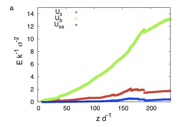
This agreement indicates that in this regime the deformation of the membrane is dominated by the bending mode. This observation is further strengthened by decomposing the total energy into bending, stretching, and self-avoidance contributions, Fig.8a, which shows that bending energy is larger than the other two by an order of magnitude.
IV.4 First and second generation d-cones
The catastrophic relaxation event in the - curve shown by the rightmost (black) arrow in Fig.7a is the signature of the birth of a second generation d-cone in the real and in-silico membranes. The mechanical response of the system after this new singularity was born can be rationalized in terms of a renormalized bending stiffness of the sheet which now resembles a cone that is thicker than the original membrane. Indeed, since bending energy of a d-cone scales as for small deformations, we expect that the ratio between the response of the first d-cone and the second d-cone will be proportional to , where and is the number of folded layers, apart from geometric factors due to the change in the contact angle. From numerical simulations results shown in Fig.5 we see that at the onset of the second d-cone. By comparing, on the other hand, the slope of the numeric - curve (Fig.8a top curve) we get . The agreement is reasonable, considering that the four layers are not glued together. Note that membranes with very small coefficient of friction will deviate from this simple estimate, since in that case the folded layers are not going to show a cooperative behavior but most likely will slide respect to each other.
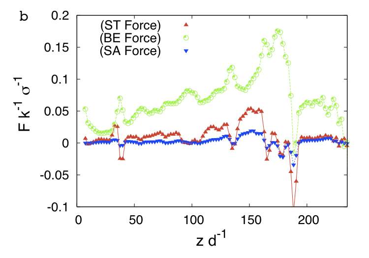
Using our argument of the renormalized stiffness constant, we turn to compute the number of folded layers for which the satellite d-cone would be created. Examining Fig.8b we see that bending and stretching forces become comparable at the onset of the new d-cone. The reason is that once the membrane has become thick enough and is stuck due to the geometrical constraint, it has to stretch if the dragging force is further increased. The satellite d-cone only occurs when the stretching component of the force becomes comparable with the bending component. Matching these two forces yields , in fair agreement with the in-silico value.
V Concluding Remarks
We have shown that under generic conditions, the mechanical response of an elastic membrane exhibits a singular evolution. This response is a consequence of bending minimization, the frictional collision between folds, and the birth of conical singularities.
In particular, we identified the satellite d-cone as a basic deformation mode of a moderately folded membrane when further constrained, which can be effectively described as a conical membrane with a larger thickness determined by the number of the folded layers. This is further supported by our experiments starting with a single-layer conical membrane. Our preliminary results and theoretical analysis show that the location of the tip of the satellite d-cone depends on the opening angle of the cone.
Based on our experimental observations and numerical simulations, we suggest a new route to model the mechanical response of crumpled surfaces, by considering an effective system that preserves the overall symmetries of the deformed one and that has a renormalized bending stiffness. It seems feasible to use this approach to expedite numerical simulations of crumpling and to make easier theoretical analysis of crumpled surfaces.
We also showed that for any real and in-silico membranes the stretching mode dominates until the stretching energy is enough to produce a global change, leading to the birth of the d-cone. Before the formation of the d-cone we showed that there is a universal scaling function for the dragging force that shows an anomalous exponent in the vertical displacement.
Finally we showed that friction does play an important role in modifying the mechanical response of the membrane. Its effects emerge soon after the first collision event between the two branches of the d-cone. We showed that friction will generically enhance the above mentioned renormalization process. It is expected that, as friction is increased, a d-cone appears sooner. This was confirmed by our experiments on membranes coated with materials having different frictional properties.
We expect our findings to be applicable to enhance energy dissipation in structures under extreme deformations by suitable modification of its frictional properties. For example, in car collisions more energy could be dissipated by designing the inner surface of metallic sheets to be structured in such a way that as soon as metal plates touch each other they get stuck. It would be interesting to see if this type of ideas can help us design structures with enhanced response to impacts.
Acknowledgments
We thank O. Tchernyshyov, I. Cabrera and E. Felton for useful comments. P.M. acknowledges support from NSF Grant DMR-0520491. S.C. acknowledges support from NSF Grant CMMI-0709187.
References
- Landau and Lifshitz (1995) L. Landau and D. Lifshitz, Theory of Elasticity- 3rd ed.(course of theoretical physics;Vol.7) (Butterwort-Heinemann, Great Britain, 1995).
- Concha et al. (2007) A. Concha, J.W. McIver III, P. Mellado, D. Clarke, O. Tchernyshyov, and R. L. Leheny, Physical Review E 75, 016609 (2007).
- Amar and Pomeau (1997) M. B. Amar and Y. Pomeau, Proc. R. Soc. London A 453, 729 (1997).
- Cerda and Mahadevan (1998) E. Cerda and L. Mahadevan, Phys. Rev. Lett. 80, 2358 (1998).
- Chaïeb et al. (1998) S. Chaïeb, F. Melo, and J.-C. Géminard, Phys. Rev. Lett. 80, 2354 (1998).
- Cerda et al. (1999) E. Cerda, S. Chaieb, F. Melo, and L. Mahadevan, Nature 401, 46 (1999).
- Lobkovsky et al. (1995) A. Lobkovsky, S. Gentges, H. Li, D. Morse, and T. Witten, Science 270, 1482 (1995).
- Lobkovsky (1996) A. E. Lobkovsky, Physical Review E 53, 3750 (1996).
- Kramer and Witten (1997) E. M. Kramer and T. A. Witten, Phys. Rev. Lett. 78, 1303 (1997).
- DiDonna (2002) B. A. DiDonna, Phys. Rev. E 66, 016601 (2002).
- Vliegenthart and Gompper (2006) G. A. Vliegenthart and G. Gompper, Nature Materials 5, 216 (2006).
- Witten (2007) T. A. Witten, Reviews of Modern Physics 79, 643 (2007).
- Tchernyshyov and Sondhi (2002) O. Tchernyshyov and S. Sondhi, Nuclear Physics B 639, 429 (2002).
- Boue et al. (2006) L. Boue, M. Adda-Bedia, A. Boudaoud, D. Cassani, Y. Couder, A. Eddi, and M. Trejo, Physical Review Letters 97, 166104 (2006).
- Concha et al. (to be published) A. Concha, S. Cheng, and P. Mellado (to be published).
- Stoop et al. (2008) N. Stoop, F. K. Wittel, and H. J. Herrmann, Physical Review Letters 101, 094101 (2008).
- Seung and Nelson (1988) H. S. Seung and D. R. Nelson, Phys. Rev. A 38, 1005 (1988).
- Matan et al. (2002) K. Matan, R. B. Williams, T. A. Witten, and S. R. Nagel, Phys. Rev. Lett. 88, 076101 (2002).