Time-delayed feedback control of delay-coupled neurosystems and lasers
Abstract
We discuss applications of time-delayed feedback control to delay-coupled neural systems and lasers, in the framework of the FitzHugh-Nagumo neuron model and the Lang-Kobayashi laser model, respectively. In the context of neural systems, we will point out some complex scenarios of synchronized in-phase or antiphase oscillations, bursting patterns, or amplitude death, induced by delayed coupling in combination with delayed self-feedback in simple network motifs. For optical systems, we will show that multiple time-delayed feedback, realized by a Fabry-Perot resonator coupled to the laser, provides a valuable tool for the suppression of unwanted intensity pulsations, and leads to stable continuous-wave operation.
keywords:
Time delay, feedback control, neural dynamics, optical controlOver the past decade control of unstable and chaotic states has evolved into a central issue in applied nonlinear science (Schöll and Schuster, 2008). Various methods of control have been developed since the ground-breaking work of Ott et al. (1990). One scheme where the control force is constructed from time-delayed signals (Pyragas, 1992) has turned out to be very robust and universal to apply, and easy to implement experimentally. In this time-delayed feedback control the control signal is built from the difference between the present and an earlier value of an appropriate system variable . It is noninvasive since the control forces vanish if the target state (a periodic state of period or a steady state) is reached. Thus the unstable states themselves of the uncontrolled system are not changed, but only their neighbourhood is adjusted such that neighbouring trajectories converge to it, i.e., the control forces act only if the system deviates from the state to be stabilized.
This paper is organized as follows: In Sec. 1, we discuss the dynamics of delay-coupled neurons and investigate the period of oscillations which can be induced for sufficiently large delay and coupling strength. The additional application of time-delayed self-feedback leads to complex scenarios of synchronized in-phase or antiphase oscillations, bursting patterns, or amplitude death. The stabilization of steady states in optical systems is studied in Sec. 2 in the framework of a modified Lang-Kobayashi model of a semiconductor laser where the time-delayed feedback is realized by a Fabry-Perot (FP) resonator.
1 Neurosystems
In order to grasp the complicated interaction between billions of neurons in large neural networks, those are often lumped into groups of neural populations each of which can be represented as an effective excitable element that is mutually coupled to the other elements (Rosenblum and Pikovsky, 2004; Popovych et al., 2005). In this sense the simplest model which may reveal features of interacting neurons consists of two coupled neural oscillators. Each of these will be represented by a simplified FitzHugh-Nagumo system (FitzHugh, 1961; Nagumo et al., 1962), which is often used as a paradigmatic generic model for neurons, or more generally, excitable systems (Lindner et al., 2004). Here we use two identical FitzHugh-Nagumo systems with parameters corresponding to the excitable regime.
We consider the simultaneous action of delayed coupling and delayed self-feedback. Here we choose to apply the self-feedback term symmetrically to both activator equations, but other feedback schemes are also possible. The equations of the system are given by
| (1) | |||||
| (2) | |||||
| (3) | |||||
| (4) |
where subsystems Eqs. (1)-(2) and (3)-(4) represent two different neurons (or neuron populations), () describing the activator (e.g., transmembrane voltages) and modelling the inhibitor (e.g., electrical conductances of the relevant ion currents across the respective membranes). Here is a bifurcation parameter whose value defines whether the system is excitable () or demonstrates periodic firing, i.e., autonomous oscillations (), is positive parameter that is usually chosen to be much smaller than unity, corresponding to fast activator variables , , and slow inhibitor variables , .
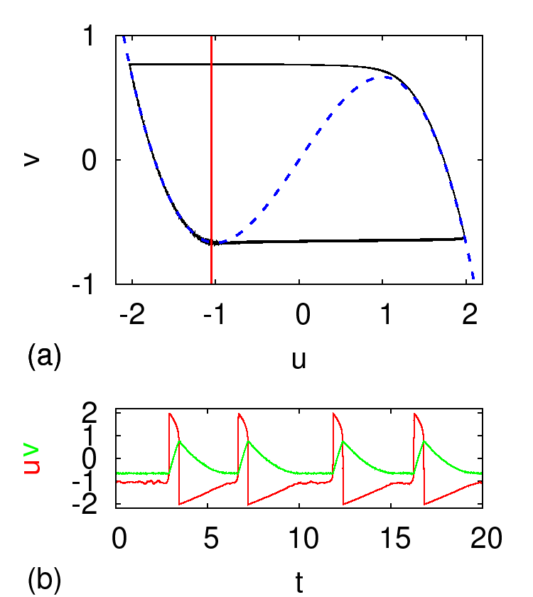
Let us illustrate the dynamics of a single neuron model by considering an uncoupled subsystem Eqs. (1) and (2) (, ) under the influence of noise. This is realized by small random fluctations modeled as Gaussian white noise with noise intensity applied to Eq. (2). We fix , and also set , . In Fig. 1(a) the dashed blue and solid red curves show the nullclines of Eq. (1) and (2), respectively, which intersect at a fixed point. The phase point that is initially placed at the fixed point stays in its close vicinity if the applied random perturbation remains small. However, if the perturbation is larger than some threshold value, the phase point makes a large excursion in the phase space before returning to the vicinity of the fixed point again. In Fig. 1(a) the black solid line illustrates such a phase trajectory and in Fig. 1(b) realizations of and time series from Eqs. (1) and (2) are shown. The motion of the phase point consists of two stages: an activation time during which the system waits for a sufficiently large perturbation before it can make an excursion, and the excursion itself. The excursion time is almost completely defined by the deterministic properties of the system and is hardly influenced by noise.
The synaptic coupling between two neurons in Eqs. (1)-(4) is modelled as a diffusive coupling considered for simplicity to be symmetric (Liley and Wright, 1994; Pinto et al., 2000; De-Miguel et al., 2001). More general delayed couplings are considered in (Buric and Todorovic, 2003). The coupling strength summarizes how information is distributed between neurons. The mutual delay in the coupling is motivated by the propagation delay of action potentials between the two neurons and .
Besides the delayed coupling we also consider delayed self-feedback in the form suggested by Pyragas (Pyragas, 1992), where the difference of a system variable , e.g., activator or inhibitor, at time and at a delayed time , multiplied by some control amplitude , is coupled back into the same system. Such feedback loops might arise naturally in neural systems, e.g., due to neurovascular couplings that has a characteristic latency, or due to finite propagation speed along cyclic connections within a neuron sub-population, or they could be realized by external feedback loops as part of a therapeutical measure, as proposed by Popovych et al. (2005). This feedback scheme is simple to implement and quite robust. One distinct advantage of this method is its noninvasiveness, i.e., in the ideal deterministic limit the control force vanishes on the target orbit, which may be a steady state or a periodic oscillation of period . In case of noisy dynamics the control force, of course, does not vanish but still remains small, compared to other common control techniques using external periodic signals, for instance, in deep-brain stimulation to suppress neural synchrony in Parkinson’s disease (Tass, 2002).
By a linear stability analysis, it can be shown that the fixed point remains stable for all values of and in case of , as without self-feedback (Schöll et al., 2008). Redefining , one obtains the factorized characteristic equation
| (5) |
Substituting the Hopf condition and separating into real and imaginary parts yields for the imaginary part
| (6) |
This equation has no solution for since .
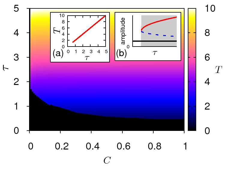
In Fig. 2 the regime of oscillations is shown in the parameter plane of the coupling strength and coupling delay . The oscillation period is color coded. The boundary of this colored region is given by the minimum coupling delay as a function of . For large coupling strength, is almost independent of ; with decreasing it sharply increases, and at some small minimum no oscillations exist at all. At the boundary, the oscillation sets in with finite frequency and amplitude as can be seen in the insets of Fig. 2 which show a cut of the parameter plane at . The oscillation period increases linearly with . The mechanism that generates the oscillation is a saddle-node bifurcation of limit cycles (see inset (b) of Fig. 2), creating a pair of a stable and an unstable limit cycle. The unstable limit cycle separates the two attractor basins of the stable limit cycle and the stable fixed point.
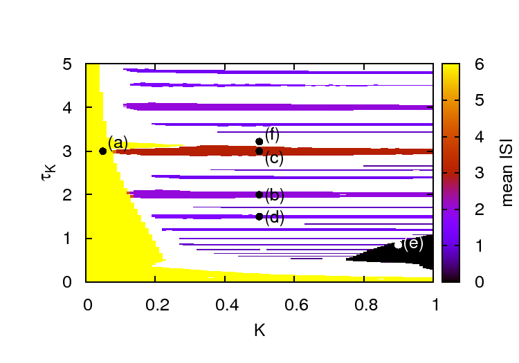
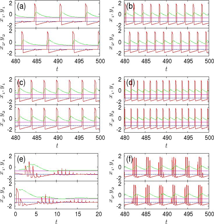
The adopted form of control allows for the synchronization of the two cells not only for identical values of and , but generates an intricate pattern of synchronization islands or stripes in the () control parameter plane (Fig. 3) corresponding to single-spike in-phase and antiphase oscillations with constant interspike intervals, see also Fig. 4(a)-(d). Further, for adequately chosen parameter sets of coupling and self-feedback control, we observe effects such as bursting patterns Fig. 4(f) and oscillator death Fig. 4(e). In addition to these effects, there exists a control parameter regime in which the self-feedback has no effect on the oscillation periods (shaded yellow).
Fig. 3 shows the control parameter plane for coupling parameters of the uncontrolled system in the oscillatory regime ( and ). We observere three principal regimes: (i) Control has no effect on the oscillation period (yellow), although the form of the stable limit cycle is slightly altered (Fig. 4(a)). (ii) Islands of in-phase and antiphase synchronization (color coded, see Fig. 4 (b)-(d)).(iii) Oscillator death (black) Fig. 4 (e)).
2 Lasers
Semiconductor lasers with external optical feedback from a mirror can be described by the Lang-Kobayashi (LK) model (Lang and Kobayashi, 1980). In dimensionless form, it consists of two differential equations for the slowly varying amplitude (envelope) of the complex electric field and the reduced carrier density (inversion) .
Here we consider a modification of the LK equations appropriate for multisection semiconductor lasers with an internal passive dispersive reflector (Tronciu et al., 2000). This is modeled by a gain function depending upon the internal dispersive feedback from the Bragg grating. Such a laser structure allows for more complex dynamic behavior including self-sustained relaxation oscillations (intensity pulsations) generated by Hopf bifurcations, as has been shown in the framework of traveling wave laser models (Bauer et al., 2004; Schikora et al., 2006). We are interested in the regime above a supercritical Hopf bifurcation where the fixed point in the uncontrolled system is unstable. Combining the rate equation for the carrier density from Ref. (Tronciu et al., 2000) with the rate equation for the complex electric field, we obtain the following form of modified LK equations:
| (7) | |||||
| (8) |
where denotes the linewidth enhancement factor, is the reduced excess injection current, is the time scale ratio of the carrier lifetime and the photon lifetime , and denotes the feedback term, which will be described in detail later.
The function , which models the internal dispersive feedback, is chosen as a Lorentzian, as proposed by Tronciu et al. (2000):
| (9) |
where denotes the height, is the width, and is the position of the resonance. The parameter is chosen such that at the laser threshold. Througout the following we will use the parameters , , and .

In Eqs. (7), the feedback term has not been specified yet. In the following, we introduce the feedback term such that it models a Fabry-Perot resonator. As opposed to the original LK model where only a single external mirror is considered, we take an external FP resonator with multiple reflections into account:
| (10) | |||||
is the delay time (cavity round trip time), is a memory parameter (mirror reflectivity), denotes the latency time originating from a single round trip between the laser and the resonator (see Fig. 5), and is the complex feedback gain with amplitude and the feedback phase which results from the associated optical phase shift. Throughout this work we use resonant feedback from the FP resonator.
The latency time , i.e., the propagation time between the laser and the FP, is correlated to the phase by the relation , where is the frequency of the emitted light. However, we consider the two parameters and as independent variables because the phase can be tuned by subwavelength changes of the separation between laser and FP resonator, on which scale the slowly varying amplitude , which depends upon , does not change. The effect of latency in time-delayed feedback was already studied in a general context in Refs. (Just et al., 1999; Hövel and Socolar, 2003; Hövel and Schöll, 2005; Dahms et al., 2007).
To investigate the stability of the cw laser emission, we will perform a linear stability analysis of the lasing state is located at where the phase of the electric field can be arbitrarily fixed to (solitary laser mode).
Using the abbreviations , and with real-valued and , the fixed point is located at . An exponential ansatz for all three variables , , and leads to the characteristic equation
In our simulations, we use the following parameters, which were chosen close to the values by Tronciu et al. (2000): , , (corresponding to , , , , , and ). Thus the intrinsic period of the uncontrolled unstable focus is .
The stability of the lasing fixed point is given by Eq. (2). We solved this equation via Newton’s method. Since the transcendental equation has an infinite number of roots, we scanned the complex plane as initial conditions of the root-finding algorithm to locate the eigenvalue with the largest real part. The parameter space consisting of , , , , and is five-dimensional for fixed and . To visualize the domain of control, we consider two-dimensional sections of this parameter space.
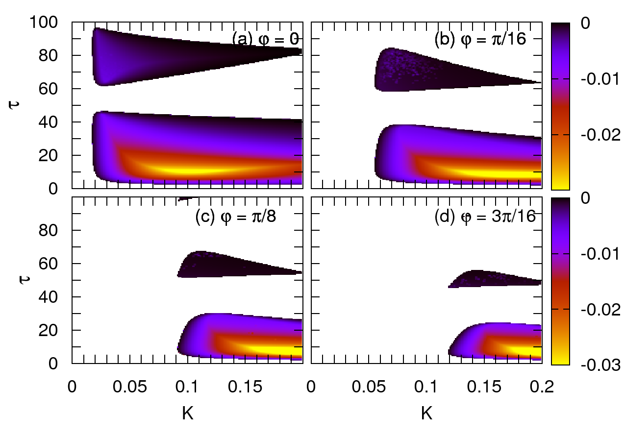
In Fig. 6, the domain of control is shown in the -plane for different values of the phase: , , , and in panels (a), (b), (c), and (d), respectively. The color code denotes the largest real part of the eigenvalues and is therefore a measure of stability. Note that only values of are plotted, thus the shaded regions correspond to a stable lasing fixed point, i.e., a stable cw output. The control domains form tongues separated by (white) regions of no control around with integer, just as in the generic model studied in Refs. (Hövel and Schöll, 2005; Dahms et al., 2007). It can be seen that the domain of control shrinks with increasing phase. Here, the domains of control are cut off by boundaries from the upper left and right for increasing phase, leading to overall smaller regions of stability. The tongues of stabilization are also slightly distorted towards smaller values of . Additionally, in this picture, the regions of optimum stability, denoted by yellow color, are shifted towards larger values of the feedback gain .
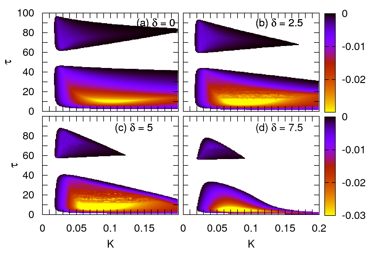
Next, we will investigate the role of the latency time in the -plane. In Fig. 7, the domain of control in the -plane is depicted for different values of the latency time, i.e., , , , and , and fixed . For larger latency times, the domains of control shrink and it can also be observed that they are bent down towards smaller values of the time delay . Note that the regions of optimum stability, denoted by yellow color, are only slightly affected by the change of the latency time.
All figures shown here were obtained for a fixed value of the memory parameter as used by Schikora et al. (2006). To investigate the dependence of the control on , we display the domains of control in the -plane for different values of the phase (, , , and ) and fixed time delay in Fig. 8. This value of was chosen based on the results from the generic model considered by Hövel and Schöll (2005); Dahms et al. (2007), where it was shown that the optimum time delay is given by , where denotes the eigenvalue of the uncontrolled system. In the LK model, the imaginary part of the eigenvalues in the uncontrolled system is given by Eq. (2) with , i.e., . This leads to an optimum time delay:
| (12) |
which yields for our parameters .
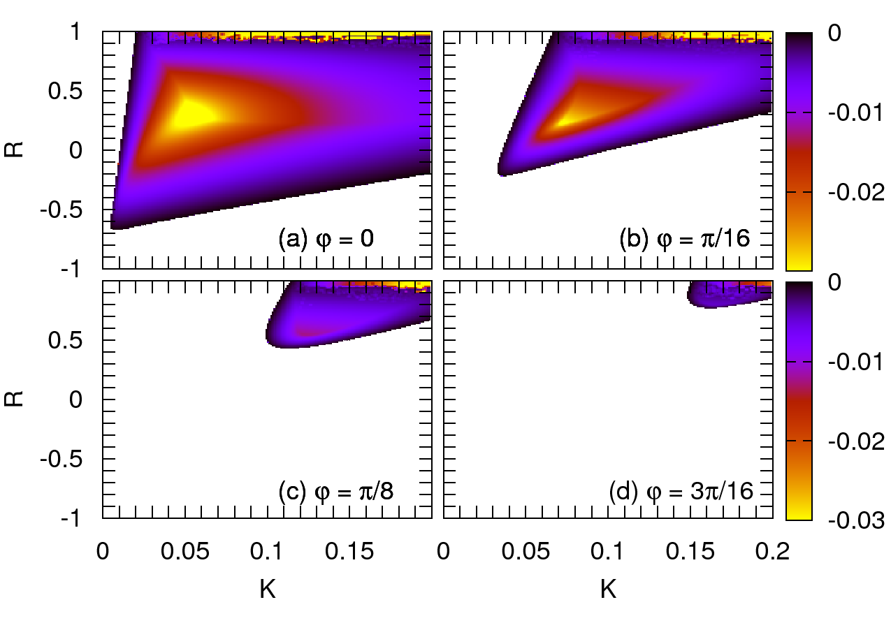
Now, in Fig. 8, it can be seen that the domain of control in the -plane has maximum size for for this choice of the time delay . [See panel Fig. 8(a).] For increasing phase, the domain of control shrinks while moving to the upper right. Stability is then only achieved in a small region at large values of and . [See panels Fig. 8(b) to (d).]
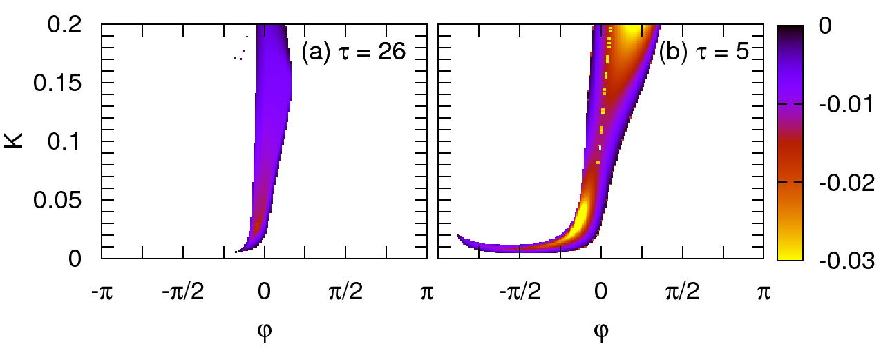
To investigate the dependence of the domain of control on the choice of the phase further, we consider another two-dimensional projection of the five-dimensional control-parameter space parameterized by feedback gain and the feedback phase . This section is depicted in Fig. 9 for two different values of the time delay and fixed . In panel (a), the time delay is chosen as , which is the optimum according to Eq. (12). Here, it can be seen that the optimum phase is located at slightly negative values for small values of the feedback gain up to . Increasing , the optimum phase changes its sign and is now located at small positive values of . For the case of , which is depicted in panel (b), stability is overall enhanced drastically. The yellow areas, denoting regions of optimum stability, are located at negative for small up to . Control is possible even for a small value of below , if the feedback gain is tuned exactly to the small range of . For larger feedback gain with , the optimum value of is located at positive values. The region of optimum stability is located at large values of around . The shape of the control domain in Fig. 9 is markedly different from that in the generic normal form model (see Figs. 6(c) and 7(c) in Ref. (Dahms et al., 2007)), but appears to be in line with full device simulations within a travelling wave model (Wünsche et al., 2008).
To summarize, we have focused on simple rate equation models of neural systems and lasers, which contain a time delay. In these systems, analytical results are important to complement computer simulations to determine whether these systems fall into categories defined by the nature of their bifurcations. This way, we have gained a more general understanding of the principles of dynamical patterns and their control. Delay dynamics can, on one hand, add to the dynamic complexity and generate bifurcations, and, on the other hand, stabilize unstable states and suppress complex dynamics. Even in the most generic neural systems described by the FitzHugh-Nagumo equation, when coupled in a minimum network of two nodes with delayed coupling and delayed self-feedback, we found complex scenarios of synchronized neuronal dynamics with in-phase or antiphase oscillations, bursting patterns, and amplitude death. In the case of the multisection semiconductor laser with an internal passive dispersive reflector and external optical feedback described by the modified Lang-Kobayashi model, we found that time-delayed self-feedback can stabilize the laser. In the regime above a supercritical Hopf bifurcation, where the fixed point in the uncontrolled system is unstable, unwanted intensity pulsations can be suppressed by time-delayed feedback control.
This work was supaported by Deutsche Forschungsgemeinschaft in the framework of Sfb 555.
References
- Bauer et al. (2004) Bauer, S., Brox, O., Kreissl, J., Sartorius, B., Radziunas, M., Sieber, J., Wünsche, H.J., and Henneberger, F. (2004). Nonlinear dynamics of semiconductor lasers with active optical feedback. Phys. Rev. E, 69, 016206.
- Buric and Todorovic (2003) Buric, N. and Todorovic, D. (2003). Dynamics of FitzHugh-Nagumo excitable systems with delayed coupling. Phys. Rev. E, 67(6), 066222.
- Dahms et al. (2007) Dahms, T., Hövel, P., and Schöll, E. (2007). Control of unstable steady states by extended time-delayed feedback. Phys. Rev. E, 76(5), 056201.
- Dahms et al. (2008) Dahms, T., Hövel, P., and Schöll, E. (2008). Stabilizing continuous-wave output in semiconductor lasers by time-delayed feedback. Phys. Rev. E, 78(5), 056213.
- De-Miguel et al. (2001) De-Miguel, F.F., Vargas-Caballero, M., and García-Pérez, E. (2001). Spread of synaptic potentials through electrical synapses in Retzius neurones of the leech. J. Exp. Biol., 204, 3241–3250.
- FitzHugh (1961) FitzHugh, R. (1961). Impulses and physiological states in theoretical models of nerve membrane. Biophys. J., 1, 445–466.
- Hövel and Schöll (2005) Hövel, P. and Schöll, E. (2005). Control of unstable steady states by time-delayed feedback methods. Phys. Rev. E, 72, 046203.
- Hövel and Socolar (2003) Hövel, P. and Socolar, J.E.S. (2003). Stability domains for time-delay feedback control with latency. Phys. Rev. E, 68, 036206.
- Just et al. (1999) Just, W., Reckwerth, D., Reibold, E., and Benner, H. (1999). Influence of control loop latency on time-delayed feedback control. Phys. Rev. E, 59, 2826.
- Lang and Kobayashi (1980) Lang, R. and Kobayashi, K. (1980). External optical feedback effects on semiconductor injection laser properties. IEEE J. Quantum Electron., 16, 347.
- Liley and Wright (1994) Liley, D.T.J. and Wright, J.J. (1994). Intracortical connectivity of pyramidal and stellate cells: estimates of synaptic densities and coupling symmetry. Network: Computation in Neural Systems, V5(2), 175–189.
- Lindner et al. (2004) Lindner, B., García-Ojalvo, J., Neiman, A., and Schimansky-Geier, L. (2004). Effects of noise in excitable systems. Phys. Rep., 392, 321.
- Nagumo et al. (1962) Nagumo, J., Arimoto, S., and Yoshizawa., S. (1962). An active pulse transmission line simulating nerve axon. Proc. IRE, 50, 2061.
- Ott et al. (1990) Ott, E., Grebogi, C., and Yorke, J.A. (1990). Controlling chaos. Phys. Rev. Lett., 64, 1196.
- Pinto et al. (2000) Pinto, R.D., Varona, P., Volkovskii, A.R., Szücs, A., Abarbanel, H.D.I., and Rabinovich, M.I. (2000). Synchronous behavior of two coupled electronic neurons. Phys. Rev. E, 62(2), 2644–2656.
- Popovych et al. (2005) Popovych, O.V., Hauptmann, C., and Tass, P.A. (2005). Effective desynchronization by nonlinear delayed feedback. Phys. Rev. Lett., 94, 164102.
- Pyragas (1992) Pyragas, K. (1992). Continuous control of chaos by self-controlling feedback. Phys. Lett. A, 170, 421.
- Rosenblum and Pikovsky (2004) Rosenblum, M.G. and Pikovsky, A. (2004). Delayed feedback control of collective synchrony: An approach to suppression of pathological brain rhythms. Phys. Rev. E, 70, 041904.
- Schikora et al. (2006) Schikora, S., Hövel, P., Wünsche, H.J., Schöll, E., and Henneberger, F. (2006). All-optical noninvasive control of unstable steady states in a semiconductor laser. Phys. Rev. Lett., 97, 213902.
- Schöll et al. (2008) Schöll, E., Hiller, G., Hövel, P., and Dahlem, M.A. (2008). Time-delayed feedback in neurosystems. Phil. Trans. Roy. Soc. London. In print (arXiv:0809.1025v1).
- Schöll and Schuster (2008) Schöll, E. and Schuster, H.G. (eds.) (2008). Handbook of Chaos Control. Wiley-VCH, Weinheim. Second completely revised and enlarged edition.
- Tass (2002) Tass, P. (2002). Effective desynchronization with bipolar double-pulse stimulation. Phys. Rev. E, 66, 036226.
- Tronciu et al. (2000) Tronciu, V.Z., Wünsche, H.J., Siebert, J., Schneider, K., and Henneberger, F. (2000). Dynamics of single mode semiconductor lasers with passive dispersive reflectors. Opt. Commun., 182, 221.
- Wünsche et al. (2008) Wünsche, H.J., Schikora, S., and Henneberger, F. (2008). Noninvasive control of semiconductor lasers by delayed optical feedback. In E. Schöll and H.G. Schuster (eds.), Handbook of Chaos Control. Wiley-VCH, Weinheim. Second completely revised and enlarged edition.