Non-linear rheology of a nanoconfined simple fluid
Abstract
We probe the rheology of the model liquid octamethylcyclotetrasiloxane (OMCTS) confined into molecularly thin films, using a unique Surface Forces Apparatus allowing to explore a large range of shear rates and confinement. We thus show that OMCTS under increasing confinement exhibits the viscosity enhancement and the non-linear flow properties characteristic of a sheared supercooled liquid approaching its glass transition. Besides, we study the drainage of confined OMCTS via the propagation of “squeeze-out” fronts. The hydrodynamic model proposed by Becker and Mugele [Phys. Rev. Lett. 91, 166104 (2003)] to describe such front dynamics leads to a conclusion in apparent contradiction with the dynamical slowdown evidenced by rheology measurements, which suggests that front propagation is not controlled by large scale flow in the confined films.
pacs:
64.70.pm, 83.50.Lh, 83.50-v, 83.60.RsSupercooled liquids share qualitative rheological features upon approaching the glass transition melt : (i) their viscosity increases dramatically, and (ii) they exhibit non-newtonian properties (shear thinning) when the time scale of mechanical forcing becomes shorter than that of structural relaxation. The precise origin of such a behavior is the subject of active theoretical and numerical investigations theory . Recently, an extension to flow situations of the mode-coupling theory (MCT) has been proposed, in order to describe this non-linear rheology FC . Now, a stringent test of theoretical predictions against experimental results requires measurements, over a large range of shear rate (), of the non-linear properties as jamming is gradually approached. These are extremely challenging to perform on atomic glass formers, because of their elevated glass transition temperature and flow stress. The most comprehensive studies to date have focused on colloidal suspensions of thermosensitive particles, in which the volume fraction, hence the distance to jamming, can be finely tuned ballauff . It has thus been shown that, in very good agreement with MCT, the flow stress of such suspensions exhibits a rate dependence all the weaker that the distance to glass transition is small, until a yield stress develops when the suspension gets jammed ballauff . Such a behavior can be considered as the rheological hallmark of the approach to glass transition.
Here, we show that increasing confinement represents an alternative pathway to bring a system close to its jammed state under well-controlled conditions. Surface Forces Apparatus (SFA) experiments have shown that simple liquids confined between solid walls below thicknesses of a few molecular diameters exhibit enhanced flow resistance IMH . From SFA experiments probing the linear response of ultrathin liquid films, Demirel and Granick (DG) concluded to a confinement-induced dynamical slowdown, akin to what occurs in supercooled liquids DG . However, this conclusion has been challenged by other groups probing the large strain shear response of confined fluids KK ; YI . Moreover, experiments by Becker and Mugele (BM) have shown that a confined liquid drains stepwise by expelling monolayers via the propagation of “squeeze-out fronts” BM . A model of the front dynamics, extending the work of Persson and Tosatti PT , led them to conclude that the confined fluid retained its bulk viscosity, dissipation enhancement arising from high friction on the confining walls.
The nature of the mechanisms by which the properties of liquids are affected by confinement at the molecular scale therefore remains an open question. Such an issue, which is of interest for the fundamental understanding of the jamming transition weeks , is also of paramount importance for boundary lubrication bo , and for nanofluidics, where the knowledge of the flow properties of liquids confined into nanometer-sized channels or structures is crucial nanoflu .
In this Letter, we report on the first SFA study in which both large strain shear rheology and squeeze-out fronts measurements are performed, in the same experimental run, on the nonpolar liquid octamethylcyclotetrasiloxane (OMCTS), which has been used in the aforementioned works.
(i) We show unambiguously, from flow curves measured over 6 decades of , that OMCTS under increasing confinement exhibits the viscosity enhancement and non-newtonian features of a supercooled liquid approaching the glass transition.
(ii) We observe squeeze-out front dynamics in quantitative agreement with that previously reported BM . When analyzed within the framework of the BM model, it results in an effective viscosity two orders of magnitude lower than that directly measured in shear. We conclude that such an apparent contradiction arises from an improper assumption by BM about the nature of the mass transport mechanism at play during front propagation.
Experiments were performed on a home-built SFA LB (Fig. 1). The liquid is confined between two atomically smooth backsilvered mica sheets glued onto crossed cylindrical lenses (radius of curvature 1 cm). The normal force is measured by means of a load cell of stiffness 9500 N.m-1. The “contact” area , over which the mica sheets elastically flatten to form a circular parallel gap in which the liquid is confined, is monitored by videomicroscopy. The thickness of the film, , is determined by multiple beam interferometry IA and fast spectral correlation Heuberg1 ; LB . Once confined under a given load, over an area , the liquid is sheared, in a plane Couette geometry, by moving laterally one surface at a velocity in the range 10m.s-1, while measuring the resulting tangential force with a cell of stiffness 5200 N.m-1. The shear stress sensitivity of the instrument is Pa. Our SFA has the unique feature of using the normal force signal as the input of a feedback loop, which allows to perform steady-state experiments over large shear amplitudes (up to hundreds of microns) under constant normal load conditions, whatever the level of confinement of the liquid. The mica sheets were prepared as described in LB2 , glued onto the cylindrical lenses using a UV curing glue (NOA 81, Norland), and cleaved with adhesive tape immediately before being installed in the SFA, so as to obtain contaminant-free surfaces FS . OMCTS from Fluka (purum grade 99%) was vacuum distilled before use. A drop (L) of the liquid, filtered through a 0.2 m membrane, was injected between the surfaces. It was then left at C for 12h in the sealed SFA, containing P2O5 to scavenge residual moisture, before beginning experiments.
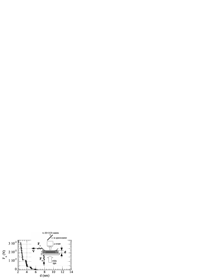 |
Fig. 1 shows a force-distance profile measured upon quasi-static approach of the surfaces: it is clearly seen that below 6 nmfootnote1 , the thickness of the confined liquid decreases by steps of approximately 8 Å, which corresponds to the minor diameter of the slightly oblate OMCTS molecule. This reflects the well-documented wall-induced layered structure of the fluid, which gives rise to the so-called solvation forces solvat .
We first focus on shear experiments performed on layered OMCTS films with thicknesses ranging from 6 down to 2 monolayers. Over the whole range of confinement and velocity explored, we have observed: (i) a smooth stable shear response (see time trace in the inset of Fig. 2b), and (ii) a steady-state value of which increases with . On Fig. 2a, we plot the steady-state flow stress versus shear rate for the different film thicknesses. The same data are plotted on Fig. 2b as the effective viscosity versus .
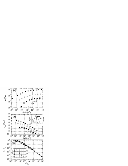 |
It can be seen that, as the OMCTS thickness is reduced from 6 to 2 monolayers:
(i) The flow stress, and hence the viscosity, steadily increases footnote2 .
(ii) The dependence of on shifts from linear (newtonian) to sublinear (shear-thinning).
(iii) The crossover shear rate, , above which non-newtonian behavior is observed, shifts to smaller values.
(iv) For 4 monolayers, power-law shear thinning (, ) at low crosses over to a quasi-plateau regime.
This set of features is characteristic of the approach to jamming, as reported experimentally ballauff and predicted by MCT and numerical simulations theory ; FC . This is further supported by the fact that curves measured for different collapse onto a single master curve when plotted as , with the zero shear viscosity (Fig. 2c). The inset of Fig. 2c shows that both and (i.e. the relaxation time of the liquid) sharply increase as the film thickness is decreased. The reduced viscosity obeys , which is consistent with theoretical predictions for sheared supercooled systems theory . Finally, the observation of a quasi-plateau regime which does not extend down to the lowest shear rates indicates that, in the present experiments, confined OMCTS approaches but does not reach jamming. This is consistent with the fact that (see inset of Fig. 2b), upon cessation of shear, the stress relaxes (i) very slowly, over s, and (ii) down to a non-measurable level.
These observations lead us to conclude, in good agreement with DG DG , that OMCTS undergoes dynamical slowdown upon increasing confinement, similarly to a supercooled system close above jamming. Such a conclusion contrasts with that of Klein KK or Israelachvili YI , who observed responses exhibiting a stick-slip dynamics which they interpret in terms of shear-melting of a confinement-induced ordered solid-like structure. Such a discrepancy might have two origins. (i) The use of different protocols for mica surface preparation: Indeed, the method employed in KK ; YI , in contrast to that described above, may lead to surface contamination by a submonolayer of nanoparticles, which have been suggested as a possible reason for the observed stick-slip behavior Pt . (ii) Differences in the crystallographic alignment of the confining surfaces, which is expected to affect the shear response of the intercalated molecular film misfit . No systematic investigation have been made so far of the effect of alignment between contaminant-free surfaces, and we therefore cannot discriminate between point (i) and (ii) above to explain differences.
We now present the results from squeeze-out experiments. During loading, we record the light intensity transmitted through the contact area, along with and . We observe, as in BM ; LB2 , that a film of thickness monolayers drains via nucleation/growth of a circular region of thickness layers (see Fig. 3). Nucleation is accompanied by elastic relaxation of the confining sheets, which are locally bent in the boundary zone connecting the regions of thickness and (Fig. 3 inset). This creates a 2D pressure gradient which then drives the monolayer expulsion BM . The local curvature of the mica sheets induces a contrast in the transmitted intensity (Fig. 3a-c) which allows us to follow with time the position of the “squeeze-out” front. We have thus measured, for successive transitions, the squeeze-out time needed to expel one monolayer from the contact area . We have done so before and after rheology experiments, and did not observe any influence of shear history on front dynamics.
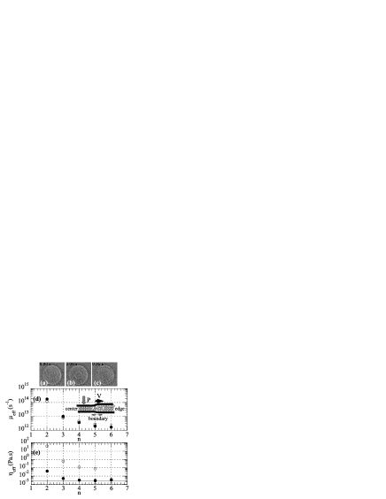 |
In the Persson and Tosatti (PT) model PT , the front velocity is related to the 2D pressure gradient by: , where and PT ; BM ( is the applied pressure, the fluid density and the molecular size), is the front velocity and a viscous drag coefficient. The latter is deduced from the squeeze-out time as PT : . On Fig. 3d we have plotted as a function of film thickness for our experiments, along with the values obtained by Becker and Mugele (BM) BM . There is quantitative agreement between both data sets. BM have extended the PT model by assuming that front propagation is controlled by a “layered” Poiseuille flow between the front and the edge of the confinement area (Fig. 3 inset), and thus proposed that should identify with the drag coefficient of a Hele-Shaw flow, i.e. , with a shear viscosity and the film thickness BM . We use this expression to infer from the front dynamics. On Fig. 3e, we compare footnote3 it to obtained from shear data. It appears that , which stays close to the bulk value down to 3-layer-thick films, is about two orders of magnitude lower than .
We propose the following explanation to this apparent paradox. Shear experiments are a straightforward way to measure , in contrast to squeeze-out experiments, which require modelling of the front dynamics to infer a viscosity. Therefore, we consider that the reliable results regarding are those from shear rheology. We are then left with the observation of squeeze-out fronts which, given the obtained in shear, travel much faster than expected from the drag mechanism assumed in the BM picture, from which we have also drawn erroneous conclusions in a recent study LB2 . This suggests that the front dynamics is not controlled by the coherent sliding of adjacent incompressible molecular layers ahead of the front. Indeed, another piece of information emerges from the force-distance profile of Fig. 1: between two steps, the film thickness is observed to decrease by about 3 Å as the force is increased. Such a thickness variation is reversible upon load reduction. This shows that layered OMCTS films are substantially compressible, hence contain a non-negligible amount of free volume, which is consistent with the fact that confined films do not reach jamming. This certainly facilitates local rearrangements, and it is therefore likely that during propagation of a squeeze-out front, molecules in the layered region ahead of it permeate between layers in order to accommodate for density variations in the vicinity of the front. The apparent low resistance to front propagation suggests that permeation, rather than large scale coherent sliding of layers, controls mass transport ahead of the fronts. It implies that, pending further modelling, front dynamics cannot be used to infer a viscosity.
In summary, we have probed the rheology of a simple fluid under molecular confinement, and conclude that its behavior is akin to that of a sheared supercooled liquid close above the glass transition. This shows, as suggested by recent experiments on colloids weeks , that confinement can be used as an alternative route to finely control the approach to jamming. Our results now raise two important questions. (i) We observe a liquidlike behavior down to the thinnest film investigated, which brings up the issue of how to cross the jamming transition under confinement. Two routes can be envisaged. It can be done by varying the chemical corrugation of the walls, as shown in friction experiments LB3 or in numerical simulations ayapa , or, as mentioned above, by changing the orientation between the crystalline lattices of the confining surfaces. (ii) We find that 6 layer-thick films already exhibit a viscosity two orders of magnitude larger than the bulk value. This raises the question of the scale below which non-bulk behavior appears, and how it compares to the range of surface forces.
We thank A. N. Morozov for fruitful discussion and C. Caroli for critical reading of the manuscript.
References
- (1) M.D. Demetriou et al., Phys. Rev. Lett. 97, 065502 (2006), and references therein. J.H. Simmons et al., J. Non-Cryst. Solids 105, 313 (1988).
- (2) A. Furukawa et al., Phys. Rev. Lett. 102, 016001 (2009). V. Lubchenko, PNAS 106, 11507 (2009). F. Varnik, O. Henrich, Phys. Rev. B 73, 174209 (2006). L. Berthier, J.L. Barrat, J. Chem. Phys. 116, 6228 (2002). R. Yamamoto, A. Onuki, Phys. Rev. E 58, 3515 (1998). P. Sollich, Phys. Rev. E 58, 738 (1998). V. Kobelev, K.S. Schweizer, Phys. Rev. E 71, 021401 (2005).
- (3) M. Fuchs, M.E. Cates, Phys. Rev. Lett. 89, 248304 (2002). K. Miyazaki, D.R. Reichman, Phys. Rev. E 66, 050101 (2002).
- (4) M. Siebenburger et al., J. Rheol. 53, 707 (2009). J. Crassous et al., J. Chem. Phys. 125, 204906 (2006).
- (5) M. L. Gee et al., J. Chem. Phys. 93, 1895 (1990).
- (6) A.L. Demirel, S. Granick, Phys. Rev. Lett. 77, 2261 (1996).
- (7) J. Klein, E. Kumacheva, J. Chem. Phys. 108, 7010 (1998).
- (8) H. Yoshizawa, J.N. Israelachvili, J. Phys. Chem. 97, 11300 (1993).
- (9) T. Becker, F. Mugele, Phys. Rev. Lett. 91, 166104 (2003). Molecular Simulation 31, 489 (2005).
- (10) B.N.J. Persson, E. Tosatti, Phys. Rev. B 50, 5590 (1994).
- (11) C.R. Nugent et al., Phys. Rev. Lett. 99, 025702 (2007).
- (12) B.N.J. Persson, Sliding Friction, Nanoscience and Technology Series, Springer, New York (2000).
- (13) J.C.T. Eijkel, A. van den Berg, Microfluid. Nanofluid. 1, 249 (2005), and references therein.
- (14) L. Bureau, Rev. Sci. Instrum. 78, 065110 (2007).
- (15) J.N. Israelachvili, J. Colloid Interface Sci. 44, 259 (1978).
- (16) M. Heuberger, Rev. Sci. Instrum. 72, 1700 (2001).
- (17) L. Bureau, A. Arvengas, Phys. Rev. E 78, 061501 (2008).
- (18) P. Frantz, M. Salmeron, Tribol. Lett. 5, 151 (1998).
- (19) Steps are observed below 9 nm. The first ones, occuring at 10-5N, are not visible on the plot of Fig. 1.
- (20) H.K. Christenson, D.W.R. Gruen, R.G. Horn, J.N. Israelachvili, J. Chem. Phys. 87, 1834 (1987).
- (21) have been measured under a pressure going from 1.5 MPa () to 7.5 MPa (). We have checked that depends weakly on at constant thickness. Its increase thus cannot be ascribe to an increase in , and is due to geometrical confinement.
- (22) J.N. Israelachvili et al., Langmuir 22, 2397 (2006).
- (23) H. Yoshizawa, J.N. Israelachvili, Thin Solid Films 246, 71 (1994). Y. Zhu, S. Granick, Phys. Rev. Lett. 87, 096104 (2001).
- (24) We compare, for each , with measured at a shear velocity equal to the average front velocity.
- (25) L. Bureau, C. Caroli, T. Baumberger, Phys. Rev. Lett. 97, 225501 (2006).
- (26) K.G. Ayappa, R. K. Mishra, J. Phys. Chem. B 111, 14299 (2007).