Dual Behavior of Antiferromagnetic Uncompensated Spins in NiFe/IrMn Exchange Biased Bilayers
Abstract
We present a comprehensive study of the exchange bias effect in a model system. Through numerical analysis of the exchange bias and coercive fields as a function of the antiferromagnetic layer thickness we deduce the absolute value of the averaged anisotropy constant of the antiferromagnet. We show that the anisotropy of IrMn exhibits a finite size effect as a function of thickness. The interfacial spin disorder involved in the data analysis is further supported by the observation of the dual behavior of the interfacial uncompensated spins. Utilizing soft x-ray resonant magnetic reflectometry we have observed that the antiferromagnetic uncompensated spins are dominantly frozen with nearly no rotating spins due to the chemical intermixing, which correlates to the inferred mechanism for the exchange bias.
pacs:
75.60.Jk, 75.70.Cn, 61.12.HaThe tremendous advances of spintronics research initiated by the discovery of interlayer exchange coupling IEC-Grunberg-1988 and giant magnetoresistance GMR-Baibich-1988 ; GMR-Binasch-1989 uses extensively the exchange bias (EB) effect to control the magnetization of ferromagnetic components. This is a consequence of the direct exchange at the interface between feromagnetic and antifereomagnetic layers and/or nanoscale heterostructures which causes a shift and a broadening of the hysteresis loop of the ferromagnet. This effect which was engineered by nature a few billion years ago mcenroe:2007 , was experimentally discovered 60 years ago by Meiklejohn and Bean (M&B) bean:1956 when studying Co particles embedded in their natural oxide (CoO) matrix. Extensive experimental and theoretical studies of the EB effect provide now sufficient understanding for utilizing it as a probe for further fundamental research iskhakov:2004 ; salabas:2006 ; lenz:2007 ; chen:2009 .
The EB and coercive fields of the biased ferromagnet (F) are determined essentially by the magnetic properties of the adjacent antiferromagnet (AF) and interfacial spin structure. Initially, the antiferromagnet was considered to be ideally rigid under the torque exerted during the reversal of the ferromagnetic layer bean:1956 . Soon afterwards, this constraint has been lifted allowing the AF spins to rotate as a whole during the magnetization reversal of the ferromagnet meiklejohn:1962 . The bulk AF spins may be displaced from their rigid orientation or they even can reverse under the torque exerted by the interfacial coupling. This leads to an onset temperature (blocking temperature) and AF critical thickness for the EB to occur. These parameters are determined by the anisotropy constant of the AF layer as well as by the nature of the interfacial coupling.
Most recently, yet another proximity effect is being experimentally unveiled for the interface of EB bilayers ohldag:2003 ; roy:2005 ; radu:jmmm:2006 ; bruck:2008 ; blackburn:2008 ; radu:2009 ; mishra:2009 : the proximity of the F layer leads to depth uncompensated (UC) interfacial AF spins which may be loose and frozen. They affect the interfacial coupling and mediate coercivity in the F layer, therefore, contributing essentially to the understanding of the EB effect.
In this Letter we explore the dependence of the EB coercive fields on the anisotropy of the AF layer. Through numerical analysis of the phase diagram we determine the variation of the AF anisotropy constant as a function of the nanoscale AF thickness, which exhibits a finite size effect. We show that this is a robust and unique capability of EB effect. We further demonstrate with soft-x-ray resonant magnetic reflectometry (XRMR) that for sputter-deposited NiFe/IrMn bilayers an insignificant chemical intermixing minimizes the amount of UC AF spins rotating with the F. We show that at nearly ideal exchange biased interfaces, the amount of frozen UC AF spins dominates and displays a characteristic depth dependence near the interface. Almost ideal interfaces are also the basis for extracting the influence of the AF magnetic anisotropy on the development of EB.
To further provide the confidence in the underlying EB mechanism, we provide a consistent correspondence between the dual behavior of UC AF spins components studied by XRMR and interfacial parameters contributing to the numerical analysis of EB.
A series of specimens Si (100)/SiO2/Cu (50 Å)/ Ni81Fe19 (75 Å)/ Ir20Mn80 (tAF =0, 10, 15, 20, 25 35 Å)/Cu (25 Å) were grown on thermally oxidized Si wafers by using the dc magnetron sputtering technique. The base pressure in the sputtering chamber was better than 210-8 mbar. The partial Ar pressure during growth was set to a minimum value of 1.510-3 mbar. During growth, the substrates were intentionally kept at room temperature (RT) in order to avoid any additional thermal interdiffusion at the F/AF interface. The uniaxial magnetic anisotropy was induced in the F layer by applying an in-situ external magnetic field of 2 kOe parallel oriented with respect to the film surface. This saturated ferromagnetic state provides the means to further induce the unidirectional anisotropy into the AF layer during growth. As a seed and capping layer we used a 50 Å and 25 Å thick Cu layers, respectively. The excellent match between the lattice parameter of Cu and Ni81Fe19 promotes a low interfacial roughness which is required for high quality EB bilayers. The thicknesses of the samples were quartz calibrated and verified with x-ray reflectivity.
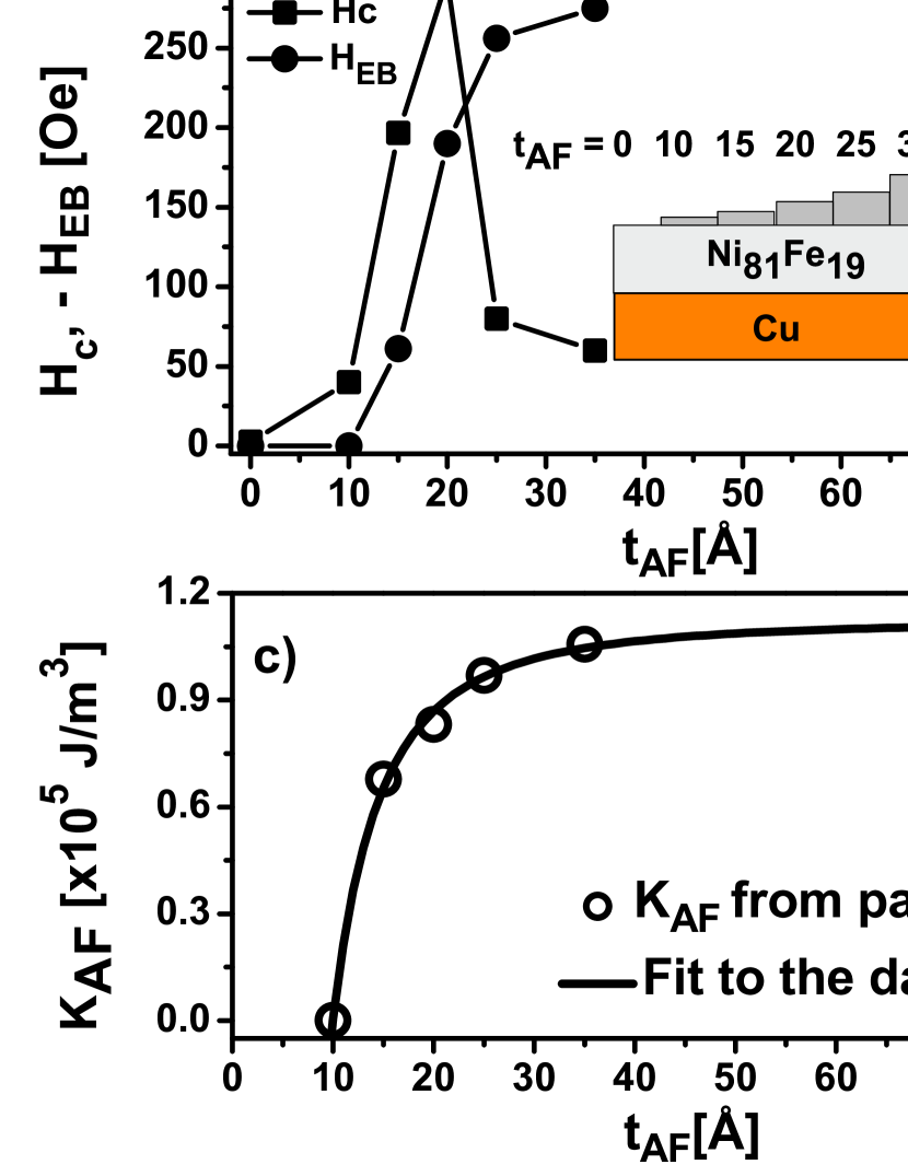
The samples have been investigated at room temperature by using the magneto-optical Kerr effect in a longitudinal geometry. In Fig. 1a the azimuthal dependence of EB field(HEB) and coercive field (Hc) are shown for a representative sample. This provides the orientation of the uniaxial and unidirectional anisotropy induced during growth in an applied magnetic field, defined as =0. The hysteresis loop at this orientation further provides the coercive and EB fields for each sample. Both quantities are plotted in Fig. 1b as a function of the AF layer thickness (tAF). Fig. 1b presents the so-called phase diagram for the EB and coercivity which is of crucial importance for defining the basic microscopic mechanism for EB.
The characteristic behavior of the NiFe/IrMn system is very similar to the prediction of the M&B model meiklejohn:1962 ; rz:2008 . Experimentally, two regions are clearly visible in the phase diagram: a) a first region from tAF=0 Å to tAF=25 Åwhere the EB field vanishes and coercive field is strongly enhanced and b) a second region with tAF higher than 25 Å where the EB occurs and the coercive field is reduced. Within the M&B model the AF is supposed to rotate under the torque created by the interfacial exchange coupling, therefore, transferring anisotropy energy into the F layer. This is seen as a peak feature of the Hc with a sharp upturn at t. Above the critical thickness for EB, the AF is rigid as a whole, acquiring slight deviation from its equilibrium position during the magnetization reversal. Experimentally, this is revealed by an abrupt onset of the HEB which is accompanied by a decrease of the Hc. Interestingly, this particular behavior of Hc and HEB across the critical AF thickness is not predicted by the Mauri model maurimodel:1987 . Therefore, the experimental data (Fig. 1a,b) clearly confirm the validity of the M&B mechanism of EB for these bilayers rz:2008 .
Nevertheless, deviations from the M&B model are still important. Above the AF critical thickness the coercive field is still enhanced. For instance, far from the critical thickness, at tAF=35 Å the coercive field is about 50 Oe. This value is much higher as compared to the coercive field of permalloy(PyNi81Fe19) layer, which for our samples is about 3 Oe (the experimental point at tAF=0, in Fig. 1b). In order to account for this enhanced coercivity, a new model Spin Glass (SG) model was recently introduced which suggests that a magnetically disordered interface may promote enhanced coercivity at the expense of EB field. The main assumption of the SG model is that the AF anisotropy is reduced at the interface allowing the formation of frozen and rotating AF spins which further affects the coupling strength and mediate coercivity into the F layer radu:jpcm:2006 .
We use this model to analyze the experimental data. First we simulate the azimuthal dependence (Fig. 1a) of the Hc and HEB for an AF thickness of tAF=35 Å. The sample was rotated around its normal in 5 degree steps. For each orientation a hysteresis loop was measured which further provided the Hc and HEB. The unidirectional behavior for the EB field is clearly seen as a major behavior(down triangles in Fig. 1a). Along the applied field direction during growth the coercive field is enhanced at and =180 deg. The parameters extracted form the simulations(lines in Fig. 1a) are JEB=0.185 J/m2, f=90 %, and =7 deg, where, JEB is the interfacial coupling constant, f is a conversion factor and is the disordered layer anisotropy orientation radu:jpcm:2006 . The origin of this disorder layer is related to the symmetry breaking at the interface as well as to the chemical roughness and inter-diffusion radu:jpcm:2006 ; mccord:2008 ; camarero:2009 . Using the f and JEB values extracted above we have further simulated the phase diagram shown in Fig. 1b by reducing the AF anisotropy to match the measured hysteresis loops for different AF thicknesses. This provides the averaged AF anisotropy constant as a function of AF thickness which is depicted in Fig. 1c). Note that the absolute values of the AF anisotropy is made possible due to the design of the samples, where only the AF thickness is varied, keeping the interface and the magnetic properties of the F layer unaffected by varying only the AF thickness.
Strikingly, the AF anisotropy exhibits a finite size effect. When the dimensions of the magnetic materials are reduced towards the critical correlation lengths for which long range order cannot be sustained, the AF ordering temperature is reduced with respect to the bulk value Jensen:2006 . The ordering temperature can be related to the geometric confinement of the magnetic energy, via scaling laws Jensen:2006 ; ambrose:1996 ; weschke:2004 ; he:2007 . Here we propose a similar power law (see Ref. ambrose:1996 ) for the anisotropy constant:
| (1) |
where, is the bulk AF anisotropy, is the correlation length at the measuring temperature, and is the so called shift exponent for finite-size scaling. This seems justified since the critical temperature is characterized by the disappearance of the AF magnetic anisotropy. Fitting the experimental AF anisotropy data (see Fig. 1e) leads to the following parameters: Å, , and . The parameter corresponds to the critical thickness for the onset of the AF anisotropy which further suggests that the Néel temperature of a of 10 Å thick IrMn film is 300 K. This is also clearly seen in the Fig. 1b as a sharp upturn of the coercive field. The value of the shift exponent is related to the critical exponent of the correlation length as . According to Jensen and Bennemann Jensen:2006 , the non-universal parameter does not agree with but is related to the coupling constants in the thin films. Most importantly, this analysis provides the average anisotropy constant for thicker films. In the past only the possibility to extract the AF anisotropy at a critical AF thickness mauri:1987 ; steenbeck:2004 for EB was explored. In the light of finite-size effects, the AF anisotropy extracted at a reduced thickness as in Ref mauri:1987 underestimates its the absolute value.
In order to provide further confidence for the EB mechanism assumed above, we concentrate now on the dual behavior of the AF interfacial components accounted for by the conversion factor, f. An unity value for the conversion factor indicates an ideal interface with no rotating UC AF spins , whereas a zero value for f radu:jpcm:2006 . would translate in a large fraction of rotating AF spins and vanishing number of frozen-in AF UC spins.
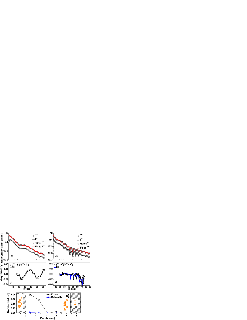
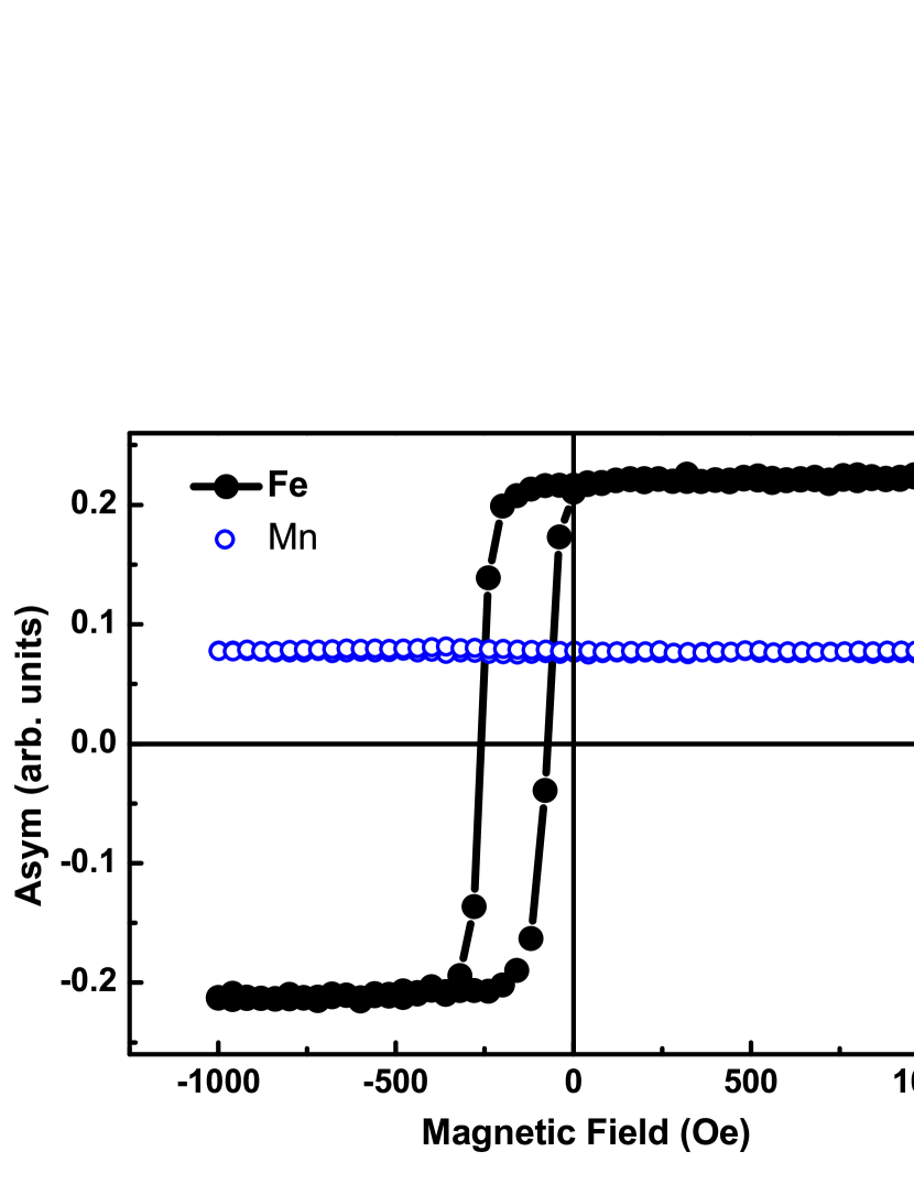
To probe the UC AF components we have measured element specific hysteresis loops (Fig. 2) and reflectivities (Fig. 3a,c) for a representative sample.XRMR measurements were performed at the UE46 High Field End Station (Fig. 3a,b) and the ALICE diffractometer grabis:2003 at beamline UE56-2 (Fig. 3c,d). By tuning the energy of the incident radiation close to the Mn L3 absorption edge, we have measured reflectivity curves which further allow us to select the scattering conditions for a maximum magnetic contrast at constant angle of incidence radu:jmmm:2006 . This is achieved by analyzing the asymmetry curves which are of two types: asymmetry at constant field measured for positive and negative helicities, and at constant helicity measured for positive and negative external fields: . For instance, Fig. 3b,d shows the asymmetry at constant saturation field (AH). We observe an oscillating magnetic asymmetry as a function of incident angle. In order to record a hysteresis loop we set the detector angle 2 to 35 degrees which provides significant magnetic contrast and sufficient reflected intensity. Vertically resolved element specific hysteresis loops (VR-ESHL) are plotted in Fig. 2 for both Fe and Mn resonant energies. We observe that the ferromagnetic layer behaves as expected. It shows a horizontal shift of the hysteresis loop and is symmetrically centered with respect to the magnetization axis. The VR-ESHL at the Mn resonant energy is very different. Practically, it is completed displaced with respect to the magnetization axis with a very weak vertical opening. This suggests that the UC AF component is mainly frozen. The rotating fraction of the AF UC component is barely visible in this curve.
To determine the depth profile and the relative fraction of the frozen and rotating UC spins we have analyzed the reflectivities and asymmetry curves for both frozen (Fig. 3a,b) and rotating (Fig. 3c,d) UC spins. This is achieved by fitting the experimental data with an algorithm based on the Zak’s formalism zak:1990 ; valencia:2008 . The results are shown in Fig. 3e. There the relative variation of the magnetic absorption coefficients for frozen and rotating UC spins are plotted as a function of depth. We observe that the frozen UC component contributes dominantly to the UC spins and that it extend deeper into the AF layer rz:2008 ; bruck:2008 . The rotating UC spins are contributing about ten time less to the UC spins, as compared to the frozen UC spins. They also appear to be located closer to the interface. Interestingly, the fraction of frozen ) UC spins ( is about 90 % which correlates well with the f-factor assumed by the SG Model.
In conclusion, we have studied the thickness dependence of the exchange bias and coercive fields for a nearly ideally behaved NiFe/IrMn system. Through numerical analysis of the hysteresis loops within the SG model we have deduced the absolute value of the AF anisotropy constant. We have observed that it exhibits a finite-size effect as a function of AF thickness. This provides an unprecedented opportunity to study anisotropy constants of AF thin films. To date this cannot be achieved by any other means. Utilizing XRMR technique we have directly probed the uncompensated interfacial spin components. The frozen UC spins extend deeper into the AF film, whereas the rotating ones are located closer to the interface. This supports a microscopic mechanism for exchange bias based on interfacial spin disorder.
We gratefully acknowledge Dr. Willy Mahler for providing excellent
technical support during the measurement at UE 56 (BESSY). The
ALICE diffractometer is funded
through the BMBF Contract No. 05KS7PC1.
florin.radu@helmholtz-berlin.de
References
- (1) P. Grünberg et al., Phys. Rev. Lett. 57, 2442 (1986).
- (2) M. N. Baibich et al., Phys. Rev. Lett. 306, 2472 (1988).
- (3) G. Binasch et al., Phys. Rev. B 39, 4828 (1989).
- (4) S. A. McEnroe et al., Nanotechnology 2, 631 (2007).
- (5) W. H. Meiklejohn and C. P. Bean, Phys. Rev. 102, 1413 (1956); Phys. Rev. 105, 904 (1957).
- (6) R. S. Iskhakov et al., JETP Lett. 80, 638 (2004).
- (7) E. L. Salabas et al.Nano Lett. 6, 2977 (2006).
- (8) K. Lenz et al.Phys. Rev. Lett. 98, 237201 (2007).
- (9) X. Chen et al.Appl. Phys. Lett. 94, 032506 (2009).
- (10) H. Ohldag et al., Phys. Rev. Lett. 91, 017203 (2003).
- (11) S. Roy et al., Phys. Rev. Lett. 95, 047201 (2005).
- (12) F, Radu et al., J. Magn. Magn. Mater., 300, 206 (2006).
- (13) S. Brück et al., Phys. Rev. Lett. 101, 126402 (2008).
- (14) E. Blackburn et al., Phys. Rev. B 78, 180408 (2008).
- (15) F. Radu et al., Phys. Rev. B 79, 184425 (2009).
- (16) S. K. Mishra et al., Phys. Rev. Lett. 102, 177208 (2009).
- (17) W. H. Meiklejohn, J. Appl. Phys. 33, 1328 (1962).
- (18) F. Radu and H. Zabel, Springer Tracts in Modern Physics, 227, 97 (2008).
- (19) D. Mauri et al.,J. Appl. Phys., 62, 3047 (1987).
- (20) F. Radu et al., J. Phys.: Condens. Matter 18, L29-L36, (2006).
- (21) E. Jiménez et al., Phys. Rev. B 80, 014415 (2009).
- (22) J. McCord et al., Phys. Rev. B 78, 094419 (2008).
- (23) P. J. Jensen, K. H. Bennemann, Surf. Sci. Rep. 61, 129 (2006).
- (24) T. Ambrose and C. L. Chien, Phys. Rev. Lett. 76, 1743 (1996).
- (25) E. Weschke et al. , Phys. Rev. Lett. 93, 157204 (2004).
- (26) L. He et al., J. Appl. Phys. 102, 103911 (2007).
- (27) D. Mauri et al., J. Appl. Phys. 62, 2929 (1987).
- (28) K. Steenbeck, R. Mattheis, and M. Diegel, J. Magn. Magn. Matter. 279, 317 (2004).
- (29) J. Grabis, A. Nefedov and H. Zabel, Rev. Sci. Instr. 74, 4048 (2003).
- (30) J. Zak et al.,J. Magn. Magn. Matter. 89, 107 (1990); Phys. Rev. B 43, 6423 (1991).
- (31) S. Valencia et al., J. Appl. Phys. 104, 023903 (2008).