Optical control of Faraday rotation in hot Rb vapor
Abstract
We demonstrate controlled polarization rotation of an optical field conditional on the presence of a second field. Induced rotations of greater than rad are seen with a transmission of , corresponding to a ratio of phase shift to absorption of . This combination of large, controlled rotation and low loss is well-suited for the manipulation of both classical and quantum light pulses.
The ability to manipulate optical pulses is central to the advancement of information and communications technology nphoton . All-optical switching switchrev has the advantage that the optical information can be processed without conversion to an electrical signal. An all-optical switch is produced by using an optical control field to modify the refractive index or the absorption of the medium, i.e., the real or the imaginary part of the electrical susceptibility, and . For example, in electromagnetically induced transparency (EIT) Harris98 ; YanPRA01 or off-resonance Raman resonances ScullyPRL91 ; ScullyPRL92 ; YavuzPRL08 a strong control field is employed to reduce the absorption at a particular frequency. Reducing the intensity of the control field to the single photon level is of interest for certain quantum information protocols qi . All-optical switching at low light levels has been demonstrated using EIT Zhang07 , and also using transverse optical pattern formation GauthierSci ; GauthierPRA08 .
An additional important criteria in an optical switch is high fidelity transmission of the input field to reduce the loss of information. The requirement of a large modulation depth concomitant with low absorption suggests that controlling the phase, or , is preferable, as in electro-optic devices such as the Mach-Zehnder modulator MZ . In this case, the figure of merit of the switching process is characterized by the change in the birefringence of the medium divided by absorption, , i.e., the ratio of the phase shift to the optical depth, . We note that for a two-state resonance, the Kramers-Kronig relations show that this ratio is largest far from resonance where the dispersion is also smaller Siddons09 . The change in can be between different polarization modes of the light field giving rise to birefringence or Faraday rotation. Polarization rotation of a linearly polarized optical field has been studied extensively in atomic systems. Such rotations may be induced by an applied magnetic field, i.e., the Faraday effect Bud ; F91 ; SiddonsNature , by an applied electric field fstark , or by spin polarizing the medium, i.e., the paramagnetic Faraday effect Happer67 ; Wieman76 ; Buell ; Hammerer ; polzik . For optical switching, a rotation angle of rad is required such that two orthogonal linear polarization modes can be exchanged. An EIT scheme reported by Li et al. provides rotations in the region of rad, with loss LiPRA06 . Larger rotations at lower loss where seen by Siddons et al. using the off-resonant Faraday effect SiddonsNature , but without optical control.
In this letter we demonstrate that high fidelity modulation () of the input field using optical control in an atomic vapor. To achieve a large induced rotation with low loss, i.e., a high value of the figure of merit, , we bias the rotation of the probe using the off-resonant Faraday effect and employ a control beam to induce population transfer to modulate around this bias. We demonstrate optical control of the Faraday rotation due to both changes in the total number of atoms and due to their spin distribution. For the probe field detuned by more than 5 times the inhomogeneous atomic linewidth we observe a phase shift of radians with a loss of less than , corresponding to . This combination of large dispersion and low loss is interesting in the context of all optical manipulation of both classical and quantum light pulses, for example, all-optical single qubit rotations for photons Petro05 . As a large rotation is achieved off-resonance the process potentially can be operated at high bandwidth of order GHz SiddonsNature . In addition, by combining this technique with the dispersive filtering properties of the Faraday effect F91 ; F93 ; Abel09 one could realize an optically tunable narrowband filter.

Figure 1 shows a schematic of the experimental apparatus along with the energy level scheme used to observe the optically controlled Faraday effect on the D1 () transition of rubidium. The source of probe light was an external cavity diode laser (ECDL) at 795 nm. The probe laser output polarization was linearly polarized and attenuated to be less than W. The beam had a radius of 0.8 mm. After passing through a half-wave plate the beam was sent through a 75 mm heated vapor cell containing the Rb isotopes according to the ratio 87Rb:85Rb of 99:1. Heating and magnetic field was provided by a solenoid, based on the design of Ref. McCarron07 . Upon transmission through the cell, the two orthogonal linear polarizations of the beam were separated with a polarizing beam splitter (PBS) cube and sent to a differencing photo-diode. For balanced detection of rotation the polarization plane was set to an angle of to the axis of the analyzing PBS cube Huard .
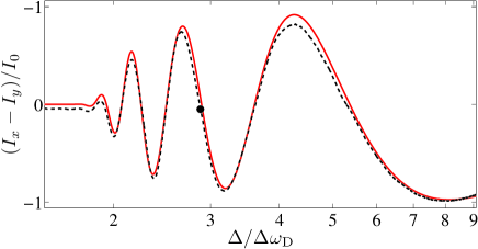
Figure 2 shows the effect of an applied magnetic field on the polarization of the probe beam transmitted through the cell. The signal detected is the intensity difference of the two orthogonal linear polarizations and normalized by the off-resonant intensity , and is related to the polarization angle of the light SiddonsNature . Oscillations in the signal are seen due to the spectral dependence of the Faraday rotation. Figure 2 also shows the calculated theoretical signal obtained by diagonalizing the complete Hamiltonian of the system. Good agreement with experimental data is seen: any difference is due to unbalanced photo detectors.
To investigate optical control of the Faraday rotation we fix the detuning of the probe laser at detuning where the polarimeter signal is close to zero (indicated by the dot in Fig. 2) and add an optical control field resonant with the D2 line () at 780 nm. The control beam was linearly polarized with a spot size of 2 mm ( radius), and counter-propagated through the cell at an angle of mrad. A natural abundance Rb cell was used as a frequency reference to calibrate the detuning of the control field relative to the D2 line (see Fig. 1).
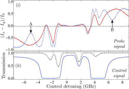
In Figure 3 we show the response of the Faraday rotation signal as a function of the frequency of the control field. Figure 3(i) shows the differencing signal for the probe for the same temperature and magnetic field as Fig. 2. Figure 3(ii) shows the transmission of the 2 mW control beam through the experiment cell and a weaker beam through the reference cell. Between the two 87Rb absorption lines the control field appears to have little effect on the difference signal, but close to resonance and at greater detunings the effect of optical control is significant. The maximum/minimum signal corresponds to alignment with the axis before folding back upon itself for greater rotation angles. Increasing the control power increases the rotation angle whilst retaining similar spectral dependence, hence the dips seen in the 30 mW curve in Fig. 3(i) correspond to rotations beyond rad to the input beam, most noticeable at points A and B. Note the magnitude of the maximum and minimum signals are not equal because the detectors in the differencing photo-diode are not perfectly balanced.
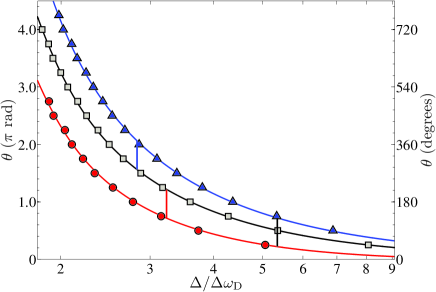
Extracting a rotation angle from this data is not trivial since the extrema of the signal depend on the transmission of the probe, which is spectrally dependent. Instead, we fix the frequency of the control laser and scan the probe light in a region red detuned from the D1 line. Figure 4 shows the resulting difference signal produced in the presence of the control field. Plots (i) and (ii) show the influence of the applied control field with its frequency fixed at the two points of maximum rotation shown in Fig. 3. From these plots we are able to take the absolute angular rotation, , of the probe using the zero-crossings and extrema (which are independent of transmission: see Ref. SiddonsNature ). The measured rotations are shown in Fig. 5. It can be seen that rotations of many radians are possible with the Faraday effect, as observed in previous studies SiddonsNature ; Siddons09 . For the rotation angle of rad induced by the applied magnetic and optical fields, the change in refractive index , though changes of and higher are possible for larger fields (see Ref. SiddonsNature ).
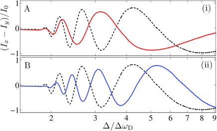
In order to calculate the optically induced rotations we extended our steady-state model used to generate the theory curve in Fig. 4 by setting the populations of the atomic states as independent parameters. This model quantitatively imitates the behavior of the optical pumping inducing the controlled Faraday rotation. Population transfer via a polarized pump is modeled as a change in the state populations; transfer by pumping is modeled as an anisotropy in the state populations, the paramagnetic Faraday effect. For the case of no pumping, an equilibrium population produces an excellent fit to data. Decreasing the population of the 87Rb by 2.5%, with an anisotropy such that there is an increased occupation of the states, reproduces the effect of a red-detuned control field; increasing the population by 16%, with an anisotropy which increases the occupation of the states, reproduces the blue-detuned control field effect. The parameters used here on an ad hoc basis agree with the expected pumping behavior: the red-detuned beam pumps depletes the population of the ground state being probed. As such the rotation is decreased with respect to the equilibrium case. The opposite is true for the blue-detuned beam. The anisotropy is due to the pump polarization changing from its initially linear state to being highly elliptical as it propagates through the medium.
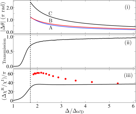
By taking the difference of the curves in Fig. 5 we can obtain the rotation caused by switching amongst the three cases of no control field, and red/blue detuned control. Curves A and B in Fig. 6(i) show the magnitude of the rotation between control field on and off, with rotation and transmission for red detuning. Note that the red- and blue-detuned cases have opposite sign, so that the difference between these two (curve C) has a greater magnitude, achieving at transmission. The transmission from Fig. 6(ii) was used to calculate the optical density, which in turn was used to calculate the figure of merit, shown in Fig. 6(iii). The figure of merit is for detunings up to . This is more than an order of magnitude larger than previous work e.g. for Ref. LiPRA06 , and to for other experiments Ent02 ; Choi07 ; YangJPB08 . From the theory curve, the figure of merit is essentially constant beyond two Doppler widths from resonance. This is ideal for broadband light where large differential dispersion over the spectrum of the pulse can lead to distortion SiddonsNature . The theoretical and measured figure of merit do not agree close to zero detuning, since the probe beam was sufficiently strong to optically pump the medium, and alter its transmission through the medium; whereas the theory curve is based on the weak probe limit which in the case of the Rb D1 line is 10 nW Siddons08 .
In summary, we have demonstrated the controlled polarization rotation of one optical field due to the presence of another, with high transmission of both beams. A continuous-wave field was used to incoherently pump atoms into a dark ground state, a process which typically takes s Pearman02 . Hence this process allows rapid switching, and has applications as a dynamic half-wave plate, a tunable Faraday dichroic beam splitter Abel09 , or polarization modulation of single photons in a similar manner to the amplitude modulation performed using an EOM Harris08 .
Optical control of the Faraday effect could be used for all-optical single qubit rotations for photons Petro05 and consequently opens new perspectives for all-optical quantum information processing. In the current experiment, a relatively strong control field is required. In future work, a pulsed field will be used to coherently drive population into the excited state in a time less than the excited state lifetime. From a simulation of population dynamics, only a small amount of anisotropy in the occupation of atomic states is required to observe rotations necessary to realize orthogonally polarized photon channels. The nanosecond switching time, combined with the Gigahertz bandwidth off-resonant Faraday effect SiddonsNature could permit rapid high-fidelity switching at low light levels.
This work is supported by EPSRC. We thank J Millen and M P A Jones for discussion, technical assistance and the loan of equipment.
References
- (1) B. Dayan and Y. Silberberg, Nature Photon. 3, 429 (2009).
- (2) I. Glesk, B. C. Wang, L. Xu, V. Baby, and P. R. Prucnal, Prog. Optics 45, 53 (2003).
- (3) S. E. Harris and Y. Yamamoto, Phys. Rev. Lett. 81, 3611 (1998).
- (4) M. Yan, E. G. Rickey and Y. Zhu, Phys. Rev. A 64, 041801(R) (2001).
- (5) M. O. Scully, Phys. Rev. Lett. 67, 1855 (1991).
- (6) M. O. Scully and M. Fleischhauer, Phys. Rev. Lett. 69, 1360 (1992).
- (7) N. A. Proite, B. E. Unks, J. T. Green, and D. D. Yavuz, Phys. Rev. Lett. 101, 147401 (2008).
- (8) D. Bouwmeester, A. K. Ekbert and A. Zeilinger, The Physics of Quantum Information (Springer, New York, 2000).
- (9) J. Zhang, G. Hernandez and Y. Zhu, Opt. Lett. 32 1317 (2007).
- (10) A. M. C. Dawes, L. Illing, S. M. Clark, and D. J. Gauthier, Science 308, 672 (2005).
- (11) A. M. C. Dawes, L. Illing, J. A. Greenberg, and D. J. Gauthier, Phys. Rev. A 77, 013833 (2008).
- (12) R. G. Hunsperger, Integrated Optics: Theory and Technology (Springer, Berlin, 2002), 5th ed.
- (13) P. Siddons, C. S. Adams and I. G. Hughes, J. Phys. B. 42, 175004 (2009).
- (14) D. Budker et al., Rev. Mod. Phys. 74, 1153 (2002).
- (15) J. Menders, K. Benson, S. H. Bloom, C. S. Liu, and E. Korevaar, Opt. Lett. 16, 846 (1991).
- (16) P. Siddons, N. C. Bell, Y. Cai, C. S. Adams, and I. G. Hughes, Nature Photon. 3, 225 (2009).
- (17) Z. K. Lee et al., Appl. Phys. Lett. 69, 3731 (1996).
- (18) W. Happer and B. S. Mather, Phys. Rev. Lett. 18, 577 (1967).
- (19) W. F. Buell and M. Fink, Appl. Phys. B 60, S227 (1995).
- (20) C. Wieman and T. W. Hansch, Phys. Rev. Lett. 36, 1170 (1976).
- (21) K. Hammerer, A. S. Sorensen, E. S. Polzik, arXiv:0807.3358v4 [quant-ph] (2008).
- (22) M. Kubasik et al., Phys. Rev. A 79, 043815 (2009).
- (23) S. Li et al. Phys. Rev. A 74, 033821 (2006).
- (24) D. Petrosyan, J. Opt. B 7, S141 (2005).
- (25) R. P. Abel, U. Krohn, P. Siddons, I. G. Hughes and C. S. Adams, Opt. Lett. 34, 3071 (2009).
- (26) H. Chen, C. Y. She, P. Searcy, and E. Korevaar, Opt. Lett. 18, 1019 (1993).
- (27) D. J. McCarron, I. G. Hughes, P. Tierney, and S. L. Cornish, Rev. Sci. Instrum. 78, 093106 (2007).
- (28) S. Huard, Polarization of Light (Wiley, New York, 1997).
- (29) V. M. Entin, I. I. Ryabtsev, A. E. Boguslavsky, and Yu. V. Brzhazovsky, Opt. Commun. 207, 201 (2002).
- (30) J. M. Choi, J. M. Kim, and D. Cho, Phys. Rev. A 76, 053802 (2007).
- (31) X. Yang, S. Li, X. Cao and H. Wang, J. Phys. B 41, 085403 (2008).
- (32) P. Siddons, C. S. Adams, C. Ge, and I. G. Hughes, J. Phys. B 41, 155004 (2008).
- (33) C. P. Pearman et al., J. Phys. B 35, 5141 (2002).
- (34) P. Kolchin, C. Belthangady, S. Du, G.Y. Yin, and S. E. Harris Phys. Rev. Lett. 101, 103601 (2008).