Flow Splitting with Fate Sharing in
a Next Generation Transport Services Architecture
UNPUBLISHED DRAFT
Abstract
The challenges of optimizing end-to-end performance over diverse Internet paths has driven widespread adoption of in-path optimizers, which can destructively interfere with TCP’s end-to-end semantics and with each other, and are incompatible with end-to-end IPsec. We identify the architectural cause of these conflicts and resolve them in Tng, an experimental next-generation transport services architecture, by factoring congestion control from end-to-end semantic functions. Through a technique we call queue sharing, Tng enables in-path devices to interpose on, split, and optimize congestion controlled flows without affecting or seeing the end-to-end content riding these flows. Simulations show that Tng’s decoupling cleanly addresses several common performance problems, such as communication over lossy wireless links and reduction of buffering-induced latency on residential links. A working prototype and several incremental deployment paths suggest Tng’s practicality.
1 Introduction
Ever since TCP congestion control was introduced [56], we have found reasons to tweak it within the network. Performance enhancing proxies (PEPs) [16] improve TCP’s poor performance over loss-prone wireless links [109], intermittent mobile links [8], and high-latency satellite links [26]. Due to their effectiveness and ease of deployment, PEPs now form the technical foundation of a booming $1 billion WAN optimization market [71], and are joining the growing class of middleboxes such as firewalls [45], NATs [91], and flow-aware routers [84] pervading the Internet.
PEPs are in theory compatible with the end-to-end principle [86], which argues that reliability mechanisms need to be end-to-end but explicitly allows for in-network mechanisms to enhance performance as long as they do not replace end-to-end reliability checks. Because the Internet’s architecture lumps congestion control with end-to-end reliability in the transport layer, however, PEPs in the path cannot affect one function without interfering with the other. Many PEPs violate fate-sharing [27] by introducing “hard state” in the network, causing application-visible failures if a PEP crashes. All PEPs are incompatible with transport-neutral security mechanisms such as end-to-end IPsec [63], which prevent the PEP from seeing the relevant transport headers.
Our novel solution to this architectural dilemma is to refactor the transport layer so that PEPs can cleanly interpose on and optimize congestion control behavior, without interfering with, or even seeing the protocol headers for, end-to-end functions such as reliability. We develop this approach in the context of Tng, an experimental next-generation transport that builds on ideas introduced earlier [42, 44] to address a broader class of transport issues.
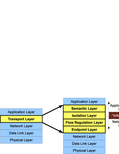
Tng breaks transports into four layers, shown in Figure 1. Tng’s Semantic Layer implements end-to-end abstractions such as reliable byte streams; its optional Isolation Layer protects upper end-to-end layers from in-path interference; its Flow Regulation Layer factors out performance concerns such as congestion control to enable performance management by PEPs; and its Endpoint Layer factors out endpoint naming concerns such as port numbers to enable clean NAT/firewall traversal [41]. We make no claim that Tng represents “the ideal architecture,” but use it here only to develop a cleaner solution to the problem of PEPs.
In this paper, we develop Tng’s Flow Layer to enable PEPs in the path to interpose on or split Flow Layer sessions, much like traditional PEPs often split TCP sessions [16]. Since Tng’s end-to-end security and reliability functions are implemented separately in higher layers, this flow splitting avoids interfering with higher end-to-end functions. Tng’s end-to-end layers treat Flow Layer sessions as “soft state,” and can restart a flow that fails due to a PEP crash or network topology change, preserving end-to-end reliability and fate-sharing. A key technical challenge flow splitting presents is joining the congestion control loops of consecutive path sections to yield end-to-end congestion control over the full path, a challenge we solve via a simple but effective technique we call queue sharing.
Through simulations we demonstrate that flow splitting via queue sharing can effectively address a variety of common performance issues, such as optimizing the performance of lossy last-mile wireless links and reducing queueing latencies on residential broadband links. While our simulations do not attempt to analyze all relevant scenarios, they illustrate the potential uses of flow splitting and suggest the feasibility of implementing it via queue sharing. We also demonstrate the feasibility of the Tng architecture through a working user-space prototype that functions on both real and simulated networks. Finally, we discuss approaches to incremental deployment, noting that with moderate costs, a Tng stack could be (1) built entirely by rearranging existing protocols without creating any new ones; (2) deployed at OS level transparently to existing applications; and (3) made compatible with and even benefit from existing PEPs by using legacy TCP as an imperfect but workable “Flow Layer.”
This work makes the following contributions. First, we identify the Internet’s architectural coupling of congestion control with end-to-end semantics in the transport layer as the source of many of the difficulties PEPs create, and present a clean solution based on decoupling these functions. Second, we introduce queue sharing as a simple but effective technique for joining congestion control loops at PEPs in the Flow Layer. Third, we demonstrate that the proposed decoupling is practical and addresses a variety of common performance issues that concern home and business users.
Section 2 of this paper examines congestion control challenges and existing solutions. Section 3 briefly summarizes the Tng architecture, and Section 4 details flow splitting via queue sharing in the context of Tng. Section 5 uses simulations to test the feasibility and efficacy of flow splitting and queue sharing, and Section 6 describes our prototype together with experiments confirming Tng’s practicality. Section 7 discusses incremental deployment strategies, Section 8 reviews related work, and Section 9 concludes.
2 The Congestion Conundrum
This section first examines the origin of TCP congestion control and the challenges it encountered as the Internet diversified, then reviews the many approaches proposed to address these challenges and their technical tradeoffs.
2.1 Why is Congestion Control in TCP?
Though network congestion was a recognized problem [30, 46], TCP did not include congestion control when it was first specified and deployed [99]. Only after several years of debate about whether congestion control should be a network or transport layer function [77, 80, 36], the transport layer approach took hold [56, 17] and eventually was officially sanctioned [7]. TCP congestion control [5] kept routers simple and performed well on typical networks of the time. To do so, TCP endpoints infer congestion information from nothing but the absence of timely packet arrival, using an implicit heuristic model of the way typical network components are expected to behave. But this inference approach assumes that all devices on the path behave consistently according to this model, an assumption somewhat contrary to the Internet’s original purpose of making diverse physical networks interoperate [27], and soon proven inaccurate [12].
Arguments for end-to-end congestion control sometimes invoke the end-to-end principle, but the principle’s original formulation [86] concerns reliability, and explicitly acknowledges that performance concerns may justify in-path mechanisms augmenting (but not replacing) end-to-end reliability checks. The inclusion of congestion control in TCP thus appears more a product of historical expedience than an application of deep internetworking principles.
2.2 Patching Up TCP Congestion Control
As the Internet grew to incorporate network technologies that violate the assumed model of network behavior underlying TCP’s inferences, a vast array of techniques appeared to make TCP perform adequately over these new technologies. We classify these techniques into brute force, link-layer fixes, new inference schemes, explicit feedback, transport interposition, and mid-loop tuning.
Brute Force: A seductively easy “sledgehammer solution” to many TCP ills is simply to open parallel TCP streams over one path, either at transport [90] or application level [4]. This approach effectively amplifies TCP’s aggressiveness, boosting throughput at the cost of fairness [39]. MulTCP [29] achieves the same effect in a single TCP stream.
Link-Layer Fixes: Most wireless networks perform link-layer retransmission to reduce TCP’s misinterpretation of radio noise as congestion, at the costs of introducing delay variation and reordering, and/or risking redundant retransmissions by the two layers [108, 55]. Forward error correction can reduce losses while minimizing delay and reordering, but incurs bandwidth overhead on all packets, not just those affected [25]. While link-layer fixes are useful, they incur unnecessary costs to delay/jitter-sensitive and loss-tolerant non-TCP traffic, and cannot address other issues affecting TCP such as high end-to-end round-trip times.
New Inference Schemes: Each significant new networking technology has spawned efforts to modify TCP endpoints to make better congestion control inferences when run over that technology: e.g., for mobile [20], satellite [2], wide-area wireless [89, 21], high-speed [38, 62], and ad hoc [68] networks. But there is an elephant in the room: in a diverse internetwork, one path may cross several technologies in turn—e.g., a wired LAN, then a satellite uplink, a high-speed transatlantic cable, and finally a remote ad hoc network. But we can choose only one end-to-end scheme for any single path; separate schemes tuned to each technology are insufficient if none performs well on the combination. The extensive parallel literatures on high-speed [6] and wireless [68] congestion control schemes rarely interact or experiment over diverse paths, giving us little optimism that any inference-based end-to-end scheme will perform well on all current, let alone future, network technologies.
New inference schemes also face the burden of competing fairly with legacy flows [58], a constraint that may be in conflict with the goals of the new scheme itself. TCP Vegas [18], for example, works well and minimizes end-to-end delay if run alone on a network, but cannot compete fairly with traditional TCP flows [73], because the signal Vegas responds to—queue build-up—is fundamental to prevailing loss-based congestion control. Vegas can be modified to compete fairly by adding a loss-based component [98], but doing so eliminates Vegas’s benefit of low delay.
Explicit Feedback: Schemes like CSFQ [95] and XCP [59] for high-speed networks, and ATCP [67] and ATP [96] for wireless networks, require routers to provide more information, such as explicit notification of losses [9], congestion [81], or link failures [51], to the TCP endpoints. But Internet router upgrades are feasible today only if done incrementally, one administrative domain at a time. Since an end-to-end path may cross several domains, congestion control schemes requiring router upgrades cannot be deployed end-to-end but only in restricted domains.
Transport Layer Interposition: Network operators often do not control end hosts and have little leverage to make users adopt new end-to-end congestion control schemes; they must instead make prevalent TCP implementations perform well by managing heterogeneity within the network. TCP-splitting PEPs [16] interpose on transport connections as they cross specific links or administrative boundaries, e.g., optimizing loss-prone [109] or mobile [8] wireless links. These PEPs “split” an end-to-end connection into multiple sections, applying specialized algorithms to network segments exhibiting non-traditional behavior. A PEP cannot interpose on the transport’s congestion control loop without interposing on its semantic functions as well, however, breaking TCP’s end-to-end reliability and fate-sharing [27]. Transport interposition also interferes with end-to-end IPsec [63], since interposition is effectively a “man-in-the-middle attack” [16].
Mid-loop Tuning: An alternative to interposition is for a PEP to manipulate a connection from the middle of a congestion control loop; we refer to this approach as mid-loop tuning. For mobile/wireless networks, Snoop [11] caches TCP segments and retransmits them when it detects non-congestion packet loss; M-TCP [19] manipulates TCP’s receive window to trick the sender into throttling transmission without reducing its congestion window. PEPs for high-speed networks use ACK splitting [57, 26] to trick the sender into into increasing its congestion window more quickly, and window stuffing [26] to compensate for end hosts with receive buffers too small for the bandwidth-delay product.
While mid-loop tuning avoids violating TCP’s end-to-end semantics, it is still incompatible with IPsec, as IPsec prevents PEPs from seeing or modifying the relevant transport headers. Mid-loop tuning may also interfere destructively with modifications to end host congestion control algorithms, as occurred between Snoop and SACK [106]. Multiple PEPs residing on one end-to-end path unbeknownst to each other can also interfere: e.g., if a TCP connection crosses wide-area links, each with an ACK splitting PEP that multiplies the sender’s congestion window increase rate by a factor of , the combination may unexpectedly multiply the sender’s aggressiveness by . Finally, mid-loop tuning by definition exploits a transport’s vulnerability to manipulation, and such vulnerabilities are exploitable for malicious purposes as well; parallel research efforts are now devoted to closing these same vulnerabilities [87, 92].
3 Refactoring the Transport
This section briefly describes Tng’s overall architecture to provide context for exploring flow splitting in the rest of the paper. We focus on those aspects relevant to understanding how Tng supports flow splitting, omitting many other details of the architecture.
3.1 Architectural Goals
Tng’s functional layering, illustrated in Figure 1, builds on previously proposed ideas [44] by decomposing the Internet’s traditional transport layer with a goal of cleanly separating network-oriented from application-oriented functions. We define network-oriented functions to be those concerning reliable and efficient network operation: functions that network operators care about, such as who is using the network and how it is performing. We define application-oriented functions as those concerning only application endpoints, such as application content and the end-to-end transport abstractions that applications build on. Tng’s lower Endpoint and Flow Regulation Layers implement what we consider the network-oriented functions of endpoint identification and congestion control, respectively, while Tng’s Isolation and Semantic Layers implement the application-oriented functions of end-to-end security and reliability.
We acknowledge that the “correct” boundary between network-oriented and application-oriented functions is not clear-cut and may be a moving target. Tng’s contribution as an architecture is not to find a perfect or complete decomposition of the transport layer, but to identify specific transport functions that have proven in practice to be “network-oriented” contrary to their traditional placement in the transport layer, and to construct a new but incrementally deployable layering that reflects this reality and restores the “end-to-endness” of the remaining application-oriented functions.
The following sections briefly outline each Tng layer.
3.2 The Endpoint Layer
As in the OSI model [113], TCP/IP breaks application endpoint identifiers into Network Layer (IP address) and Transport Layer (port number) components, including only the former in the IP header on the assumption that the network need know only how to route to a given host, and leaving port numbers to be parsed and demultiplexed by the transport. As the Internet’s size and diversity exploded, however, network operators needed to enforce access policies that depend on exactly who is communicating—not just which hosts, but which applications and users. Now-ubiquitous middleboxes such as Firewalls [45], traffic shapers [35], and NATs [91] must therefore understand transport headers in order to enforce these network policies. Since middleboxes cannot forward traffic for transports whose headers they do not understand, new transports have become effectively undeployable other than atop TCP or UDP [85].
Recognizing that communicating rich endpoint information is a network-oriented function relevant to in-network policy enforcement, Tng factors this function into its Endpoint Layer so that middleboxes can extract this information without having to understand application-oriented headers. Tng reinterprets UDP [79] as an initial Endpoint Layer protocol already supported by most middleboxes, but we are evolving Tng to incorporate ideas on richer endpoint identities [102], NAT traversal [41, 47, 14], middlebox signaling [105, 24], NAT-friendly routing [107, 48], and other related ideas outside the scope of this paper.
3.3 The Flow Regulation Layer
As Tng’s Endpoint Layer factors out endpoint identification, the Flow Regulation Layer similarly factors out performance related functions such as congestion control, with the recognition that these functions have likewise become “network-oriented” in practice as discussed in Section 2. The Flow Layer assumes that the underlying Endpoint Layer provides only best-effort packet delivery between application endpoints, and builds a flow-regulated best-effort delivery service for higher layers to build on. In particular, the Flow Layer’s interface to higher layers includes an explicit signal indicating when the higher layer may transmit new packets.
To perform this flow regulation, the Flow Layer may either implement standard TCP-like congestion control [56], or, as we discuss in later sections, may use more specific knowledge of an underlying network technology or administrative domain. In the longer term, we envision Tng’s flow layer incorporating additional performance-related mechanisms such as end-to-end multihoming [93], multipath transmission [69], and forward error correction.
3.4 The Isolation Layer
Having factored out network-oriented transport functions into the Endpoint and Flow Layers, the optional Isolation Layer “isolates” the application from the network, and protects the “end-to-endness” of higher layers. This isolation includes two elements. First, the Isolation Layer protects the application’s end-to-end communication from interference or eavesdropping within the path, via transport-neutral cryptographic security as in IPsec [63]. Second, the Isolation Layer protects the application and end-to-end transport from unnecessary exposure to details of network topology and attachment points, by implementing location-independent endpoint identities as in HIP [76] or UIA [43], which remain stable even as devices move or the network reconfigures. The Isolation Layer’s interface to higher layers is functionally equivalent to the interface exported by the Flow Layer, but with transformed packet payloads and/or endpoint identities.
We believe the Isolation Layer represents a suitable location for end-to-end security precisely because it defines the boundary between network-oriented and application-oriented functions, thus ensuring integrity and security of the latter, while allowing middleboxes to interact with the former. In contrast with SSL/TLS [31], the Isolation layer is neutral to transport semantics and does not need to be adapted to each transport [83]. In contrast with IPsec’s standard location immediately above IP, the Isolation Layer does give up the ability to protect Endpoint and Flow Layer mechanisms from off-path DoS attacks as IPsec protects TCP’s signaling mechanisms, but if standard non-cryptographic defenses against such attacks [13, 33] are deemed insufficient, then IPsec authentication can still be deployed in Tng underneath the flow layer, ideally via a delegation-friendly scheme [107, 48] permitting controlled interposition by middleboxes.
3.5 The Semantic Layer
Tng’s Semantic Layer implements the remaining application-oriented end-to-end transport functions, particularly end-to-end reliability. In the case of TCP, these functions are all those in the original TCP protocol [99] except port numbers, including acknowledgment and retransmission, order preservation, and receive window management. Other application-visible semantics, such as RDP’s reliable datagrams [78] and SCTP’s message-based multi-streaming [93], could fit equally well into Tng’s Semantic Layer as distinct protocols.
The Semantic Layer’s interface to lower layers differs from that of traditional Internet transports in two ways. First, a Tng semantic protocol uses the Endpoint Layer’s endpoint identities (possibly transformed by the Isolation Layer) instead of implementing its own port number demultiplexing. Second, a Tng semantic protocol implements no congestion control but relies on the underlying Flow Layer to signal when packets may be transmitted. The Semantic Layer’s interface to higher layers (e.g., the application) depends on the transport semantics it implements, but need not differ in any application-visible way from existing transport APIs—a fact that could aid deployment as we discuss later in Section 7.
4 Flow Splitting in Tng
With the architectural context in place, we now focus on Tng’s support for flow splitting at the Flow Regulation Layer, in order to support in-path congestion control specialization without interfering with end-to-end transport functions.
4.1 Flow Middleboxes
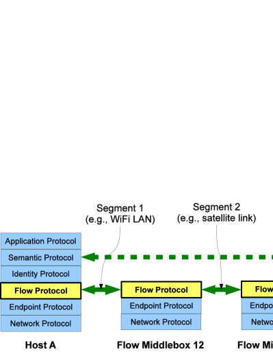
Tng enables network operators to specialize congestion control and other flow performance concerns by deploying devices we call flow middleboxes at network technology and administrative boundaries. As illustrated in Figure 2, a flow middlebox interposes on a Flow Layer session, effectively terminating one congestion control loop and starting another for the next section of the path. Each section may consist of one or many Network Layer hops: flow splitting does not imply hop-by-hop congestion control [72], although the latter might be viewed as a limit case of flow splitting.
Each flow section may use any congestion control scheme operating according to standard principles; the key technical challenge is joining these independent segments to form a single flow providing end-to-end congestion control to higher layers, a challenge we address in Section 4.3.
While flow middleboxes are similar to PEPs, they avoid the problems of PEPs discussed in Section 2.2. Since Tng’s Flow Layer implements only performance-related functions, Flow middleboxes interpose on only these functions without interfering with end-to-end functions. Flow middleboxes maintain only performance-related “soft state;” end-to-end functions can recover from a flow middlebox failure since reliability and connection-related “hard state” are located at the endpoints. We demonstrate this fate-sharing in Tng through experiments using our prototype implementation in Section 6.3.
4.2 Uses of Flow Splitting
Flow splitting can be used to improve communication performance in at least three ways, which we summarize here: reducing per-section RTT, specializing to network technology, and administrative isolation.
Reducing Per-Section RTT: A TCP flow’s throughput is adversely affected by large round-trip time (RTT), especially in competition with flows of smaller RTT [37]. Further, since information takes one RTT to propagate around the control loop, any end-to-end scheme’s responsiveness to changing conditions is limited by RTT. Subdividing a path into shorter sections reduces each section’s RTT to a fraction of the path’s RTT, which can improve both throughput and responsiveness. Proponents of hop-by-hop congestion control schemes for packet-switched [72], cell-switched [66], and wireless networks [110] have noted this benefit. The Logistical Session Layer [97] similarly leverages the reduced RTT of split paths to improve wide-area grid performance.
Specializing to Network Technology: The literature reviewed in Section 2 amply demonstrates that the best congestion control scheme for a communication path often depends on underlying network characteristics. Flow middleboxes deployed at the boundaries of a network domain can implement a congestion control specialized to that domain, taking advantage of a more precise knowledge of the domain’s characteristics from which to make inferences, and/or leveraging explicit feedback mechanisms [95, 59, 9, 81, 51] supported only within that domain. Although one path may traverse many such boundaries, each middlebox need only understand the properties of the adjacent path sections, reducing the “end-to-end” challenge of managing flow performance across an arbitrary set of network technologies to the more tractable challenge of interfacing technologies in pairwise combinations. The fact that one “side” of each flow middlebox is usually a standard wired LAN simplifies the challenge further.
Administrative Isolation: Flow splitting enables administrators to split a Flow Layer path at domain boundaries and deploy a new congestion control scheme within the domain under controlled conditions, while maintaining TCP-friendliness on other sections of paths crossing the domain. Even for legacy flows not conforming to Tng’s model—e.g., flows with congestion control embedded in the Transport Layer or no congestion control at all—administrators can enforce the use of a particular congestion control scheme within a domain by encapsulating legacy streams in a Flow Layer “tunnel” as a mechanism using per-flow state at border routers/flow middleboxes to deploy new congestion control schemes within a domain [95], or to enforce TCP-friendliness [82] or differential service agreements [49]. Flow splitting thus gives administrators the freedom to choose schemes like Vegas [18] for their desirable properties, while isolating the chosen scheme from competition with legacy Reno flows and avoiding the yoke of TCP-friendliness.
4.3 Joining Flow Sections
As mentioned earlier, the primary technical challenge in implementing flow splitting is joining multiple independently congestion controlled sections to form an end-to-end congestion controlled path. Existing TCP splitting PEPs leverage the buffer management and receive window control that TCP’s reliable byte stream abstraction provides, but these heavyweight abstractions are not well suited to Tng’s best-effort, packet-oriented Flow Layer.
Tng addresses this challenge through a simple technique we call queue sharing. We assume each flow middlebox along a split path has a queue in which it holds packets it has received on one section but not yet forwarded on to the next section. With queue sharing, the middlebox treats this queue as the meeting point for the two sections, with each section’s congestion control loop taking a role in the queue’s management: the two adjacent sections thus “share” this queue.
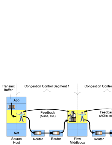
Consider for example data sent from the source host across Section 1 and arriving at the flow middlebox in Figure 3. Instead of acknowledging a data segment immediately upon reception as TCP would, the flow middlebox silently deposits the packet in its shared queue. The transmit side of the middlebox’s congestion control logic for Section 2, meanwhile, determines when the middlebox may remove packets from the shared queue and transmit them over Section 2 to the target host. When Section 2’s congestion control logic decides a packet may be transmitted, the middlebox removes and transmits a packet from the shared queue, and only then allows the receive-side logic for Section 1 to acknowledge the packet’s receipt. The middlebox in effect treats the shared queue as if it were the last router in Section 1, including the queue in Section 1’s congestion control loop so that the sender on Section 1 (the source host in this case) throttles its transmit rate if this or any other Section 1 router queue fills.
Suppose the path’s bottleneck is one of the routers in Section 2. As the bottleneck router’s queue fills, Section 2’s congestion control scheme detects this bottleneck, typically by sensing either a packet loss or delay increase depending on the congestion control scheme. The flow middlebox in response cuts its transmission rate over Section 2, thereby decreasing the rate at which it removes packets from the shared queue. As the shared queue fills, Section 1’s transmitter—the source host—notices either a loss or a delay increase and cuts its transmission rate in turn.
Queue sharing is simple and works with any congestion control algorithm as long as the middlebox manages the shared queue in the proper fashion for routers in the section feeding the queue. If that section consists of standard Internet routers, then the shared queue may be a standard drop-tail queue, or a RED [40] or ECN-marking [81] queue to improve performance. If the feeding section uses XCP [59], then the shared queue must behave like an XCP router, tagging packets flowing through it with congestion information.
4.4 Limitations of Queue Sharing
Queue sharing is appealing due to its simplicity and practical applicability as explored in following sections, but it has at least two limitations that may suggest future refinements or alternative flow joining techniques.
First, queue sharing assumes that the middlebox maintains a separate queue per flow, which may be expensive in middleboxes supporting many flows. This situation is still an improvement over the per-flow state requirements of TCP splitting PEPs, however, which typically need two queues in each direction—a receive buffer for the previous TCP session and a transmit buffer for the next.
Second, since queue sharing essentially transforms a downstream section’s congestion into “backpressure” on upstream middleboxes’ shared queues, congestion-related overheads can accumulate across these queues. If all sections of a path use loss-based congestion control [5], for example, and the last section contains the bottleneck, then not only the bottleneck router queue but each upstream middlebox queue fills before this backpressure reaches the sending endpoint, exacerbating the loss-based scheme’s delay-inducing effects.
A possible alternative to queue sharing is to layer one end-to-end congestion control loop atop a series of per-section control loops. The Flow Layer might use XCP [59] end-to-end, for example, treating the lower-level per-section congestion control loops as “virtual links” as seen by the upper-level XCP control loop. Such an approach might address the above issues, at the cost of requiring greater end-to-end coordination; we leave such alternatives to future work.
5 Simulation Experiments
To illustrate how flow splitting can address practical difficulties caused by network heterogeneity, we explore two simple but realistic scenarios via simulation. We implemented a prototype Flow Layer supporting flow splitting in the ns2 network simulator, building on existing TCP congestion control algorithms already supported by the simulator, and used it to compare relevant performance properties of flows employing flow splitting against pure end-to-end flows. These scenarios are intended to illustrate the benefits of architectural support for flow splitting, and not to exhaustively analyze or quantitatively predict real network performance using particular protocols. We leave analysis of more diverse scenarios and implementation tradeoffs to future work.
5.1 Getting Low Delay from Residential DSL
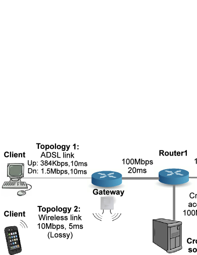
We first explore a typical scenario in which a residential DSL connection is used concurrently for both delay-sensitive activities such as gaming and bandwidth-intensive activities such as web browsing or file downloads. The simulation uses the topology shown in Figure 4 (Topology 1), in which a gateway on the ISP’s network separates the user’s client from the Internet. The client communicates with the server on the far right, but a pair of hosts generate competing cross-traffic on an intermediate network link. We configured the ADSL link according to observed parameters [32].
The ISP in this scenario offers a premium “gaming service,” in which the client’s gateway acts as a flow middlebox helping the client maintain low delay. The client’s end host or DSL modem negotiates the use of a delay-minimizing congestion control scheme over the DSL link with the flow middlebox—we use TCP Vegas [18]—but the rest of the path from the gateway to the server uses loss-based NewReno congestion control. The bottleneck for our observed flow is at the DSL link.
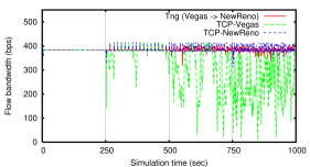
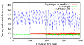
Figure 5 compares the bandwidth and round-trip delay provided by this Tng-enabled “gaming service” against the performance of either NewReno or Vegas alone operating end-to-end, in the presence of a constant upload stream from the client to the server and a varying amount of competing cross-traffic on the core Internet. The simulation adds a new TCP-NewReno cross-traffic flow every 250 seconds. As the bandwidth graph shows, end-to-end Vegas performs well until the first competing NewReno flow appears, then quickly gives up bandwidth as NewReno cross-traffic increases. End-to-end NewReno, on the other hand, competes well with the cross-traffic in securing network bandwidth, but maintains a consistently high delay—a frequent problem for users of typical DSL modems [32]. With the Tng-enabled “gaming service,” in contrast, the ISP’s flow middlebox isolates the Vegas algorithm controlling the DSL link from the NewReno algorithm controlling the path across the Internet core, enabling the Vegas section to provide low delay without competing with NewReno flows on the same link, and enabling NewReno to compete effectively for bandwidth on the Internet.
In addition to the main benefit of obtaining low delay while uploading, the split Tng flow experiences slightly lower delay than end-to-end Vegas even without cross-traffic. This effect results from the shorter feedback loop that the Vegas client experiences with Tng, operating over only the ADSL link’s 20ms RTT instead of the full path’s 120ms RTT, an example of the effects described in Section 4.2.
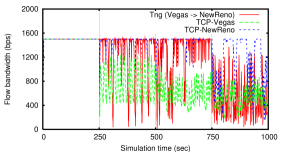
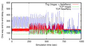
Figure 6 shows similar results during a download from the server to the client. The results are similar overall, but the Tng flow does experience some increase in delay, though not as much as end-to-end NewReno. This increase is due to our use of queue sharing to join Flow Layer sections, which causes packets crossing from the high-bandwidth NewReno core section to the lower-bandwidth DSL section to build up in a NewReno-controlled queue at the flow middlebox as described in Section 4.4. Since this queue is on the high-bandwidth side of the network and under control of the ISP, however, it can be made small to serve the low-delay demands of the client.
Overall, this instantiation of Tng combines the strengths of the different TCP variants in their specific domains, and thus provides a high-bandwidth, low-delay service that none of the end-to-end schemes could manage alone.
5.2 A Lossy Wireless Network
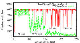
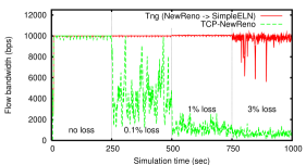
The second topology in Figure 4 uses a wireless link at the last hop with a varying loss rate. This topology is motivated by a mobile/wireless end-user who is chiefly concerned with maximizing bandwidth.
We implemented TCP-SimpleELN, a TCP variant supporting Explicit Loss Notification (ELN) [9] signals from the TCP-SimpleELN receiver. The TCP-SimpleELN receiver accepts notifications of packet loss from the underlying wireless link layer. When such a notification is received, the TCP-SimpleELN receiver sends back a message to the sender explicitly indicating packet(s) that were dropped by the link layer. The TCP-SimpleELN sender then retransmits the dropped packet(s) without modifying the congestion window.
Figure 7 shows the performance of end-to-end TCP-NewReno and an instantiation of Tng composed of TCP-SimpleELN on the last wireless hop and TCP-NewReno in the wide-area. The loss rate increases from 0 at the beginning to 0.1% at 250 seconds, then to 1% at 500 seconds, and finally to 3% at 750 seconds. Tng is able to leverage TCP-SimpleELN’s strength on the wireless link, and maximizes bandwidth for both data uploads and downloads.
Since TCP-SimpleELN relies on a link layer notification, the transport receiver must be co-located with the wireless link layer receiver. Tng makes this possible for any end-to-end flow, since the lossy link layer can be managed by flow middleboxes using TCP-SimpleELN on the link.
6 A Prototype Tng Stack
While Section 5’s simulations suggest the feasibility of joining flow sections via queue sharing, we wish to evaluate flow splitting in the context of the overall Tng architecture to validate our original goal of supporting in-path optimization without interfering with end-to-end transport functions. To do so, we built a prototype protocol suite demonstrating the proposed refactoring of transport services into Endpoint, Flow Regulation, Isolation, and Semantic Layers, thereby achieving Tng’s main goals. This section describes relevant details of our current prototype together with experiments using the prototype that confirm Tng’s feasibility and illustrate the benefits of its clean support for flow splitting.
6.1 Organization of the Prototype
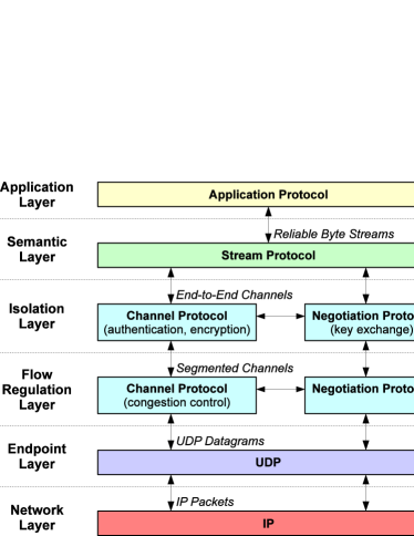
Figure 8 illustrates the overall structure of the prototype, which builds on a previous experimental prototype of the Structured Stream Transport (SST) protocol [42]. SST consists of two main components: a Channel Protocol and a Stream Protocol. The Channel Protocol implements a sequenced and congestion-controlled but unreliable and unordered packet delivery service, comparable to DCCP [64], but with optional cryptographic authentication and encryption similar to that of IPsec [63] and DTLS [83]. The Stream Protocol builds on the Channel Protocol’s delivery service to provide reliable, ordered byte streams semantically equivalent to TCP’s, but capable of being created and destroyed more efficiently, enabling fine-grained (e.g., transactional) use of these lightweight streams. This separation of functions within SST is the reason for it being the basis of our prototype: SST’s Stream Protocol nicely fits the role of Tng’s Semantic Layer, its Channel Protocol, while needed to be reworked as described below, serves as starting point for both Tng’s Flow and Isolation Layers, and its Channel Protocol already builds atop UDP as a starting point for Tng’s Endpoint Layer.
The main challenge was implementing the Flow Regulation and Isolation Layers. To do so, we borrowed a principle of the Recursive Network Architecture [103], and adapted the Channel Protocol so that this one protocol may be instantiated in different configurations to implement both the Flow Layer and the Isolation Layer. When implementing the Flow Layer, the Channel Protocol operates with congestion control enabled but cryptographic security disabled, and we modified the protocol to allow dividing an end-to-end path into segments, each running a separate instance of the Channel Protocol with an independent congestion control loop. When implementing the Isolation Layer, the Channel Protocol operates end-to-end, using self-certifying cryptographic identifiers as in HIP [76] to give hosts stable identities as they migrate among IP addresses, and using IPsec-like encryption and authentication to secure the end-to-end channel against interposition or eavesdropping. The end-to-end channel serving as the Isolation Layer runs with its own congestion control logic disabled, relying instead on the underlying, segmented Flow Layer instance(s) of the Channel Protocol to implement this function.
The Stream Protocol does not require a stream to be attached always to the same channel: instead, a stream can attach dynamically to any available channel between the appropriate pair of hosts, as identified cryptographically by the Isolation Layer. Each Flow Layer channel monitors the channel’s condition using the same packet-level acknowledgments it uses to implement congestion control, and reports its condition to higher layers. If a flow detects a stall or failure, the Isolation Layer channel atop that flow propagates this signal upward to the Semantic Layer, which attempts to construct Flow and Isolation Layer channels representing a new or alternative communication path. If a new, authenticated end-to-end channel comes online while the old one is still unusable, the Stream Protocol migrates existing streams to the new channel transparently to the application.
Associated with the Channel Protocol, SST uses a separate Negotiation Protocol for key exchange, similar to IPsec’s IKE [60] or HIP’s key exchange mechanism [75] and based on Just Fast Keying [1]. Finally, to enable hosts to find each other after changing IP addresses, SST provides a simple Registration Protocol analogous to a name service through which hosts can register their cryptographic identities with a registration server and look up the current network endpoints of other hosts by their cryptographic identities.
The prototype protocol suite runs in user space, and is implemented in C++ using the Qt event framework [104]. It includes an asynchronous networking framework that enables it, and applications using it, to be run either on real networks or in a network simulation environment for development and testing purposes. When used in the simulation environment, the protocol suite still implements complete, working protocols that exchange and process “real” packets containing user data, so it is more faithful in this respect than many simulation environments.
6.2 Validating Flow Splitting in the Prototype
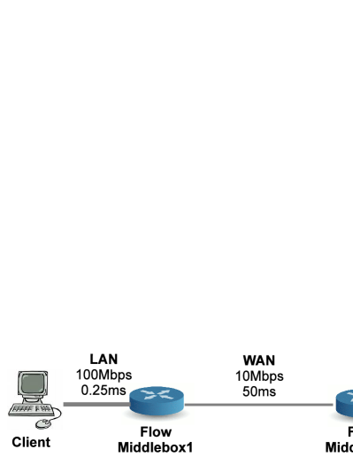
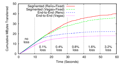
To validate flow splitting via the prototype’s Channel Protocol, we test a simple network scenario corresponding to a common use of PEPs around a high-bandwidth, long-distance link such as a reserved-bandwidth link between two sites in an organization’s private network. To simplify experimentation and provide exactly reproducible results, we run the protocol suite in the prototype’s network simulation environment. The experiment uses the simulated network topology shown in Figure 9, consisting of two high-bandwidth, low-delay LAN links surrounding a medium-bandwidth, high-delay WAN link, with the WAN link incurring a variable random loss rate.
In the Tng version of the scenario, the flow middleboxes surrounding the link interpose on Flow Layer sessions traversing the link to optimize flow performance. Since this inter-site link provides fixed point-to-point bandwidth, we assume that the WAN link itself needs no congestion control—only the LANs on both ends do. The WAN section runs a trivial “congestion control” scheme that merely maintains an administratively fixed transmission rate corresponding to the link’s bandwidth. This way a flow using the section takes no time to ramp up to full use of the section, and there is no need for special techniques to distinguish congestion from non-congestion losses since there are no congestion losses. Of course, to share the link among multiple flows the middlebox must divide the link’s fixed congestion window among the flows, similar to XCP’s fairness controller [59].
Figure 10 plots cumulated bytes transferred over time by a long reliable data transfer using the Stream Layer, over the Tng-split flow versus an equivalent end-to-end flow, using both Reno-like and Vegas-like congestion schemes. We plot cumulative bytes in this experiment instead of average bandwidth because the Stream Protocol’s byte stream reordering creates violent artificial spikes in a bandwidth plot. Every 10 seconds in the simulation, the WAN link’s random loss rate increases. This loss quickly affects end-to-end throughput as both Reno and Vegas misinterpret the random loss as congestion loss, but in the split scenario the flow middleboxes shield the endpoints and the LAN sections from these loss effects, resulting in good performance until the loss rate becomes very large.
6.3 Recovering from Flow Layer Failures
While conventional PEPs might implement the optimizations described in the previous experiments, Tng’s key novelty is its support for such optimizations without their interfering with end-to-end security or reliability. Section 6.2 already offers “proof by example” of flow splitting coexisting with end-to-end security, as the Isolation Layer channel provides end-to-end security while running atop multiple per-section Flow Layer channel instances.
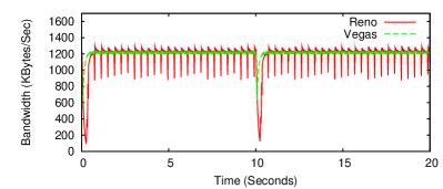
To demonstrate Tng’s preservation of end-to-end reliability [86] and fate-sharing [27] despite Flow Layer failures or network reconfigurations, as argued in Section 4.1, we now test the prototype in a simple migration scenario. Figure 11 shows a trace of an end-to-end, application-level data transfer using the prototype over a simulated 10Mbps link, where the IP address of one of the endpoints (the sender in this case) changes 10 seconds into the trace. Once the Flow Layer’s congestion control loop detects and reports a stall as described in Section 6.1, the Semantic Layer initiates the construction a new set of Flow and Isolation Layer channels to the remote host, which includes a new Registration Protocol query to find the host’s latest IP address. As the figure indicates, the prototype requires only a few round-trips after the stall to find the host’s new IP address and negotiate new end-to-end encrypted and authenticated channels, before migrating and resuming the stream transparently to the application.
If the link or network layer could provide advance warning of an impending network reconfiguration, and permit simultaneous use of the new and old network configurations during a transition period, then Tng could mask even this temporary interruption by negotiating new channels while continuing to use the old ones.
7 Deployment Strategies
Any refactoring of existing Internet protocols faces major deployment hurdles due to the Internet’s inertia, and Tng is no exception. However, we find several reasons for optimism that an architecture incorporating the principles described here could overcome these deployment hurdles. Specific strategies that can facilitate Tng’s deployment follow.
| Protocols | Header Size | Code Size | ||||
| Layer | SST | Legacy | SST | Legacy | SST | Legacy |
| Semantic | Stream | TCP | 8 | 20 | 1600 | 5300 |
| Isolation | Channel | ESP | 24 | 32 | 930 | 5300 |
| Flow | Channel | DCCP | 12 | 16 | 2900 | |
| Endpoint | UDP | UDP | 8 | 8 | 600 | 600 |
| Total | 52 | 76 | 3130 | 14100 | ||
Existing Protocol Reuse: A protocol stack supporting clean flow splitting as in Tng could be composed entirely of existing protocols: TCP with congestion control disabled as the Semantic Layer, IPsec as the Isolation Layer, DCCP as the Flow Layer, and UDP as the Endpoint Layer. This approach may not yield the most far-reaching benefits, and may incur overheads due to redundancies between layers: e.g., Table 1 compares the minimal per-packet overhead of this reuse approach against our Tng prototype for comparable functionality, as well as approximate source code line counts. Nevertheless, reuse could mitigate the difficulty of new protocol development and standardization.
Application Transparency: Our Tng prototype’s Semantic Layer already provides a reliable stream abstraction compatible with TCP’s: with careful design, a kernel implementation of Tng could replace TCP completely transparently to applications, dynamically probing the network and remote host for Tng support and falling back on TCP if necessary.
Compatibility with Existing PEPs: While a DCCP-like protocol is most suited to Tng’s Flow Layer, a Tng stack might support the use of standard TCP as a fallback “Flow Layer,” atop which the Tng stack’s true Isolation and Semantic Layer protocols would run as if a TCP “application.” While TCP’s overhead and ordering constraints may incur a performance cost, encapsulation in legacy TCP flows would make the new stack even more compatible with existing networks and capable of benefiting from existing TCP-based PEPs, and could still restore end-to-end fate-sharing by ensuring that the new Semantic Layer retains all end-to-end “hard state” and can restart failed TCP flows.
8 Related Work
Prior work has explored general protocol decomposition concepts, such as cross-layer protocol stack optimization [28], modular composition [54, 74], and protocol compilation [22] We focus in contrast on leveraging protocol decomposition to address the specific problem of supporting in-path flow optimizers cleanly.
Flow splitting is closely related to TCP splitting [109, 8, 16], retaining the simplicity, generality, and modularity of TCP splitting without interfering with end-to-end security or semantics. Many optimization techniques attempt to avoid breaking TCP’s end-to-end semantics by silently manipulating a congestion control loop “from the middle” [11, 19], but risk unexpected interactions with other PEPs on the path or with upgraded endpoints [106], and remain incompatible with end-to-end IPsec [16], as described in Section 2.2.
Like Tng’s Flow Layer, prior work has factored congestion control for other reasons: TCP control block interdependence [101], Connection Manager [10], and TCP/SPAND [112] aggregate congestion state across flows, and DCCP [64] provides an unreliable, congestion-controlled datagram transport. DCCP and CM have features that complement our Flow Layer, such as CM’s support for state aggregation and application-layer framing [28], and DCCP’s congestion control scheme negotiation. Other experimental transports such as Split-TCP [65], pTCP [53], mTCP [111], LS-SCTP [3], and SST [42] have factored congestion control from transport semantics internally for other reasons.
Tng’s Endpoint Layer, which factors and exposes application endpoint identities to the network, has precedent in Xerox Pup [15] and AppleTalk [88], which include “socket numbers” in their network-layer addresses, and Sirpent [23], which treats application-level endpoints as part of Network Layer source routes. While IP’s splitting of endpoint identity across layers is consistent with the OSI model [113], Tennenhouse argued against layered multiplexing due to the difficulty it presents to real-time scheduling [100], and Feldmeier elaborated on related issues [34]. Much prior work has focused on firewalls and NATs, such as NAT traversal schemes [41, 47, 14], signaling protocols [105, 24], and NAT-friendly routing architectures [107, 48]. We expect that future work exploring Tng’s Endpoint Layer will draw heavily from this body of work.
Tng’s Isolation Layer is inspired by location-independent addressing systems such as SFS [70], [94], HIP [76], and and UIA [43], and by IPsec’s application-transparent security [63]; Tng’s contribution is to position such mechanisms so as to avoid interference with either the network-oriented or application-oriented functions of traditional transports.
9 Conclusion
Driven by the challenges of optimizing Internet performance over today’s explosive diversity of network technologies, the booming network acceleration industry grew in the US from $236 million in 2005 [50] to $1 billion in 2009 [71], and now markets PEPs implementing a variety of transport- and higher-level acceleration techniques. If conventional transport layer PEPs proliferate like firewalls and NATs already have, we predict that: (a) new transports and end-to-end IPsec will become practically undeployable even with UDP encapsulation for NAT/firewall traversal, because they will perform poorly on heterogeneous paths that optimize only TCP and not UDP traffic; and (b) multiple independent mid-loop tuning PEPs will increasingly be found accidentally cohabiting the same TCP paths, causing unpredictable control interactions and mysterious network failures.
By factoring congestion control to support flow splitting, Tng demonstrates an architecturally clean alternative to conventional PEPs, providing the simplicity and generality of TCP splitting, but without risking unpredictable interactions among mid-loop tuning PEPs, and without interfering with end-to-end transport-neutral security, end-to-end semantics, or fate-sharing. While we make no pretense that this paper defines a complete next-generation transport services architecture, or that flow splitting alone would drive the widespread deployment of such an architecture, we hope that the many benefits potentially achievable at once from a careful factoring of congestion control from transport semantics [101, 10, 112, 3, 42] will eventually drive the deployment of a next-generation architecture incorporating these ideas.
References
- [1] W. Aiello et al. Just fast keying: Key agreement in a hostile Internet. TISSEC, 7(2):1–32, May 2004.
- [2] I. F. Akyildiz, G. Morabito, and S. Palazzo. TCP-Peach: A new congestion control scheme for satellite IP networks. Transactions on Networking, 9(3), June 2001.
- [3] A. A. E. Al, T. Saadawi, and M. Lee. LS-SCTP: a bandwidth aggregation technique for stream control transmission protocol. Computer Communications, 27(10):1012–1024, June 2004.
- [4] M. Allman, H. Kruse, and S. Ostermann. An application-level solution to TCP’s satellite inefficiencies. In 1st WOSBIS, Nov. 1996.
- [5] M. Allman, V. Paxson, and W. Stevens. TCP congestion control, Apr. 1999. RFC 2581.
- [6] A. Baiocchi, A. P. Castellani, and F. Vacirca. YeAH-TCP: Yet another highspeed TCP. In 5th PFLDnet Workshop, Feb. 2007.
- [7] F. Baker, ed. Requirements for IP version 4 routers, June 1995. RFC 1812.
- [8] A. V. Bakre and B. Badrinath. Implementation and performance evaluation of indirect TCP. IEEE Transactions on Computers, 46(3):260–278, Mar. 1997.
- [9] H. Balakrishnan and R. H. Katz. Explicit loss notification and wireless web performance. In IEEE Globecom Internet Mini-Conference, Nov. 1998.
- [10] H. Balakrishnan, H. S. Rahul, and S. Seshan. An integrated congestion management architecture for Internet hosts. In SIGCOMM, Sept. 1999.
- [11] H. Balakrishnan, S. Seshan, E. Amir, and R. H. Katz. Improving TCP/IP performance over wireless networks. In 1st MOBICOM, Nov. 1995.
- [12] C. Barakat, E. Altman, and W. Dabbous. On TCP performance in an heterogeneous network: A survey. Technical Report 3737, INRIA, July 1999.
- [13] S. Bellovin. Defending against sequence number attacks, May 1996. RFC 1948.
- [14] A. Biggadike et al. NATBLASTER: Establishing TCP connections between hosts behind NATs. In ACM SIGCOMM Asia Workshop, Apr. 2005.
- [15] D. R. Boggs, J. F. Shoch, E. A. Taft, and R. M. Metcalfe. Pup: An internetwork architecture. IEEE Transactions on Communications, 28(4):612–624, Apr. 1980.
- [16] J. Border et al. Performance enhancing proxies intended to mitigate link-related degradations, June 2001. RFC 3135.
- [17] R. Braden, ed. Requirements for Internet hosts — communication layers, Oct. 1989. RFC 1122.
- [18] L. Brakmo and L. Peterson. TCP Vegas: End to end congestion avoidance on a global Internet. IEEE Journal on Selected Areas in Communications, 13(8):1465–1480, Oct. 1995.
- [19] K. Brown and S. Singh. M-TCP: TCP for mobile cellular networks. Computer Communications Review, 27(5):19–43, Oct. 1997.
- [20] R. Cáceres and L. Iftode. Improving the performance of reliable transport protocols in mobile computing environments. IEEE Journal on Selected Areas in Communications, 13(5):850–857, June 1995.
- [21] C. Casetti, M. Gerla, S. Mascolo, M. Sanadidi, and R. Wang. TCP Westwood: End-to-end congestion control for wired/wireless networks. Wireless Networks, 8(5):467–479, Sept. 2002.
- [22] C. Castelluccia and W. Dabbous. Generating efficient protocol code from an abstract specification. In SIGCOMM, Aug. 1996.
- [23] D. R. Cheriton. Sirpent: A high-performance internetworking approach. In SIGCOMM, Sept. 1989.
- [24] S. Cheshire, M. Krochmal, and K. Sekar. NAT port mapping protocol, June 2005. Internet-Draft (Work in Progress).
- [25] A. Chockalingam, M. Zorzi, and V. Tralli. Wireless TCP performance with link layer FEC/ARQ. In ICC, June 1999.
- [26] Cisco, Inc. Rate based satellite control protocol, 2004.
- [27] D. D. Clark. The design philosophy of the DARPA Internet protocols. In SIGCOMM, Aug. 1988.
- [28] D. D. Clark and D. L. Tennenhouse. Architectural considerations for a new generation of protocols. In SIGCOMM, pages 200–208, 1990.
- [29] J. Crowcroft and P. Oechslin. Differentiated end-to-end internet services using a weighted proportional fair sharing TCP. ACM CCR, 28(3):53–69, July 1998.
- [30] D. W. Davies. The control of congestion in packet switching networks. IEEE Transactions on Communications, 20(3):546–550, June 1972.
- [31] T. Dierks and E. Rescorla. The transport layer security (TLS) protocol version 1.1, Apr. 2006. RFC 4346.
- [32] M. Dischinger, A. Haeberlen, K. P. Gummadi, and S. Saroiu. Characterizing residential broadband networks. In IMC, Oct. 2007.
- [33] W. Eddy. TCP SYN flooding attacks and common mitigations, Aug. 2007. RFC 4987.
- [34] D. C. Feldmeier. Multiplexing issues in communication system design. In SIGCOMM, Sept. 1990.
- [35] P. Ferrill. Network traffic shaping tools. Processor, 28(16):4, Apr. 2006.
- [36] G. G. Finn. A connectionless congestion control algorithm. ACM CCR, 19(5):12–31, Oct. 1989.
- [37] S. Floyd. Connections with multiple congested gateways in packet-switched networks, part 1: One-way traffic. ACM CCR, 21(5):30–47, Oct. 1991.
- [38] S. Floyd. HighSpeed TCP for large congestion windows, Dec. 2003. RFC 3649.
- [39] S. Floyd and K. Fall. Promoting the use of end-to-end congestion control in the Internet. Transactions on Networking, 7(4):458–472, Aug. 1999.
- [40] S. Floyd and V. Jacobson. Random early detection gateways for congestion avoidance. Transactions on Networking, 1(4):1063–6692, Aug. 1993.
- [41] B. Ford. Peer-to-peer communication across network address translators. In USENIX, Apr. 2005.
- [42] B. Ford. Structured streams: a new transport abstraction. In SIGCOMM, Aug. 2007.
- [43] B. Ford et al. Persistent personal names for globally connected mobile devices. In 7th OSDI, Nov. 2006.
- [44] B. Ford and J. Iyengar. Breaking up the transport logjam. In HotNets-VII, Oct. 2008.
- [45] N. Freed. Behavior of and requirements for Internet firewalls, Oct. 2000. RFC 2979.
- [46] M. Gerla and L. Kleinrock. Flow control : A comparative survey. IEEE Transactions on Communications, 28(4):553–574, Apr. 1980.
- [47] S. Guha and P. Francis. Characterization and measurement of TCP traversal through NATs and firewalls. In IMC, Oct. 2005.
- [48] S. Guha, Y. Takeday, and P. Francis. NUTSS: A SIP-based approach to UDP and TCP network connectivity. In SIGCOMM 2004 Workshops, Aug. 2004.
- [49] A. Habib and B. Bhargava. Unresponsive flow detection and control using the differentiated services framework. In PDCS, Aug. 2001.
- [50] M. Hall. WAN optimization dominated by startups, growing fast. Enterprise Networking Planet, Apr. 2006.
- [51] G. Holland and N. Vaidya. Analysis of TCP performance over mobile ad hoc networks. Wireless Networks, 8(2), Mar. 2002.
- [52] R. Housley. Using advanced encryption standard (AES) counter mode with IPsec encapsulating security payload (ESP), Jan. 2004. RFC 3686.
- [53] H.-Y. Hsieh and R. Sivakumar. pTCP: An end-to-end transport layer protocol for striped connections. In 10th ICNP, Nov. 2002.
- [54] N. C. Hutchinson and L. L. Peterson. The x-Kernel: An architecture for implementing network protocols. IEEE Transactions on Software Engineering, 17(1), Jan. 1991.
- [55] H. Inamura et al. Impact of layer two ARQ on TCP performance in W-CDMA networks. In ICDCS, Mar. 2004.
- [56] V. Jacobson. Congestion avoidance and control. pages 314–329, Aug. 1988.
- [57] K. Jin, K. Kim, and J. Lee. SPACK: rapid recovery of the TCP performance using split-ack in mobile communication environments. In IEEE Region 10 Conference, Sept. 1999.
- [58] S. Jin et al. A spectrum of TCP-friendly window-based congestion control algorithms. Transactions on Networking, 11(3):341–355, June 2003.
- [59] D. Katabi, M. Handley, and C. Rohrs. Internet congestion control for high bandwidth-delay product networks. In SIGCOMM, Aug. 2002.
- [60] C. Kaufman, Ed. Internet key exchange (IKEv2) protocol, Dec. 2005. RFC 4306.
- [61] S. Kelly and S. Frankel. Using HMAC-SHA-256, HMAC-SHA-384, and HMAC-SHA-512 with IPsec, May 2007. RFC 4868.
- [62] T. Kelly. Scalable TCP: Improving performance in highspeed wide area networks. Computer Communications Review, 33(2):83–91, Apr. 2003.
- [63] S. Kent and K. Seo. Security architecture for the Internet protocol, Dec. 2005. RFC 4301.
- [64] E. Kohler, M. Handley, and S. Floyd. Datagram congestion control protocol (DCCP), Mar. 2006. RFC 4340.
- [65] S. Kopparty, S. V. Krishnamurthy, M. Faloutsos, and S. K. Tripathi. Split TCP for mobile ad hoc networks. In IEEE GLOBECOM, Nov. 2002.
- [66] H. T. Kung and A. Chapman. The FCVC (flow-controlled virtual channels) proposal for ATM networks: A summary. In 1st ICNP, Oct. 1993.
- [67] J. Liu and S. Singh. ATCP: TCP for mobile ad hoc networks. IEEE Journal on Selected Areas in Communications, 19(7):1300–1315, July 2001.
- [68] C. Lochert, B. Scheuermann, and M. Mauve. A survey on congestion control for mobile ad-hoc networks. WCMC, 7(5):655–676, June 2007.
- [69] L. Magalhaes and R. Kravets. Transport level mechanisms for bandwidth aggregation on mobile hosts. In 9th ICNP, Nov. 2001.
- [70] D. Mazières, M. Kaminsky, M. F. Kaashoek, and E. Witchel. Separating key management from file system security. In 17th SOSP, Dec. 1999.
- [71] S. McGillicuddy. WAN optimization market passes $1 billion; Cisco takes the lead. SearchEnterpriseWAN.com, Mar. 2009.
- [72] P. P. Mishra and H. Kanakia. A hop by hop rate-based congestion control scheme. In SIGCOMM, Aug. 1992.
- [73] J. Mo, R. J. La, V. Anantharam, and J. Walrand. Analysis and comparison of TCP Reno and Vegas. In INFOCOM, Mar. 1999.
- [74] R. Morris, E. Kohler, J. Jannotti, and M. F. Kaashoek. The Click modular router. In 17th SOSP, Dec. 1999.
- [75] R. Moskowitz et al. Host identity protocol, Apr. 2008. RFC 5201.
- [76] R. Moskowitz and P. Nikander. Host identity protocol (HIP) architecture, May 2006. RFC 4423.
- [77] J. Nagle. Congestion Control in IP/TCP Internetworks, Jan. 1984. RFC 896.
- [78] C. Partridge and R. Hinden. Version 2 of the reliable data protocol (RDP), Apr. 1990. RFC 1151.
- [79] J. Postel. User datagram protocol, Aug. 1980. RFC 768.
- [80] W. Prue and J. Postel. Something a host could do with source quench: The source quench introduced delay (SQuID), July 1987. RFC 1016.
- [81] K. Ramakrishnan, S. Floyd, and D. Black. The addition of explicit congestion notification (ECN) to IP, Sept. 2001. RFC 3168.
- [82] A. Rangarajan and A. Acharya. ERUF: Early regulation of unresponsive best-effort traffic. In 7th ICNP, Oct. 1999.
- [83] E. Rescorla and N. Modadugu. Datagram transport layer security, Apr. 2006. RFC 4347.
- [84] L. G. Roberts. The next generation of IP — flow routing. In SSGRR, July 2003.
- [85] J. Rosenberg. UDP and TCP as the new waist of the Internet hourglass, Feb. 2008. Internet-Draft (Work in Progress).
- [86] J. H. Saltzer, D. P. Reed, and D. D. Clark. End-to-end arguments in system design. TOCS, 2(4):277–288, Nov. 1984.
- [87] S. Savage et al. TCP congestion control with a misbehaving receiver. Computer Communications Review, 29(5), Oct. 1999.
- [88] G. S. Sidhu, R. F. Andrews, and A. B. Oppenheimer. Inside Appletalk. Addison-Wesley, 2rd edition, 1990.
- [89] P. Sinha et al. WTCP: A reliable transport protocol for wireless wide-area networks. Wireless Networks, 8(2):301–316, Mar. 2002.
- [90] H. Sivakumar, S. Bailey, and R. Grossman. PSockets: The case for application-level network striping for data intensive applications using high speed wide area networks. In SC2000, Nov. 2000.
- [91] P. Srisuresh and K. Egevang. Traditional IP network address translator (Traditional NAT), Jan. 2001. RFC 3022.
- [92] M. Stanojevic, R. Mahajan, T. Millstein, and M. Musuvathi. Can you fool me? towards automatically checking protocol gullibility. In HotNets-VII, Oct. 2008.
- [93] R. Stewart, ed. Stream control transmission protocol, Sept. 2007. RFC 4960.
- [94] I. Stoica et al. Internet indirection infrastructure. In SIGCOMM, Aug. 2002.
- [95] I. Stoica, S. Shenker, and H. Zhang. Core-stateless fair queueing: A scalable architecture to approximate fair bandwidth allocations in high speed networks. In SIGCOMM, Aug. 1998.
- [96] K. Sundaresan, V. Anantharaman, H. Hsieh, and R. Sivakumar. ATP: A reliable transport protocol for ad-hoc networks. In ACM MOBIHOC, June 2003.
- [97] M. Swany. Improving throughput for grid applications with network logistics. In SC2004, Nov. 2004.
- [98] K. Tan, J. Song, Q. Zhang, and M. Sridharan. Compound TCP: A scalable and TCP-friendly congestion control for high-speed networks. In INFOCOM, Apr. 2006.
- [99] Transmission control protocol, Sept. 1981. RFC 793.
- [100] D. L. Tennenhouse. Layered multiplexing considered harmful. In 1st International Workshop on Protocols for High-Speed Networks, May 1989.
- [101] J. Touch. TCP control block interdependence, Apr. 1997. RFC 2140.
- [102] J. Touch. A TCP option for port names, Apr. 2006. Internet-Draft (Work in Progress).
- [103] J. D. Touch, Y.-S. Wang, and V. Pingali. A recursive network architecture. Technical Report ISI-TR-2006-626, University of Southern California Information Sciences Institute, Oct. 2006.
- [104] Trolltech. Qt cross-platform application framework. http://trolltech.com/products/qt/.
- [105] UPnP Forum. Internet gateway device (IGD) standardized device control protocol, Nov. 2001. http://www.upnp.org/.
- [106] S. Vangala and M. A. Labrador. The TCP SACK-aware snoop protocol for TCP over wireless networks. In Vehicular Technology Conference, Oct. 2003.
- [107] M. Walfish, J. Stribling, M. Krohn, H. Balakrishnan, R. Morris, and S. Shenker. Middleboxes no longer considered harmful. In USENIX Symposium on Operating Systems Design and Implementation, Dec. 2004.
- [108] J. W. Wong and V. C. Leung. Improving end-to-end performance of TCP using link-layer retransmissions over mobile internetworks. In ICC, June 1999.
- [109] R. Yavatkar and N. Bhagawat. Improving end-to-end performance of TCP over mobile internetworks. In Workshop on Mobile Computing Systems and Applications, Dec. 1994.
- [110] Y. Yi and S. Shakkottai. Hop-by-hop congestion control over a wireless multi-hop network. IEEE Transactions on Networking, 15(1):133–144, Feb. 2007.
- [111] M. Zhang, J. Lai, A. Krishnamurthy, L. Peterson, and R. Wang. A transport layer approach for improving end-to-end performance and robustness using redundant paths. In USENIX, June 2004.
- [112] Y. Zhang, L. Qiu, and S. Keshav. Speeding up short data transfers: Theory, architectural support and simulation results. In 10th NOSSDAV, June 2000.
- [113] H. Zimmermann. OSI reference model—the ISO model of architecture for open systems interconnection. IEEE Transactions on Communications, 28(4):425–432, Apr. 1980.