Further author information: (Send correspondence to Carmelo Arcidiacono)
E-mail: carmelo@arcetri.astro.it, Telephone: +39 055 2752 293
Laboratory Testing the Layer Oriented Wavefront Sensor for the Multiconjugate Adaptive optics Demonstrator
Abstract
The Multiconjugate Adaptive optics Demonstrator (MAD) for ESO-Very Large Telescopes (VLT) will demonstrate on sky the MultiConjugate Adaptive Optics (MCAO) technique. In this paper the laboratory tests relative to the first preliminary acceptance in Europe of the Layer Oriented (LO) Wavefront Sensor (WFS) for MAD will be described: the capabilities of the LO approach have been checked and the ability of the WFS to measure phase screens positioned at different altitudes has been experimented. The LO WFS was opto-mechanically integrated and aligned in INAF - Astrophysical Observatory of Arcetri before the delivering to ESO (Garching) to be installed on the final optical bench. The LO WFS looks for up to 8 reference stars on a 2arcmin Field of View and up to 8 pyramids can be positioned where the focal spot images of the reference stars form, splitting the light in four beams. Then two objectives conjugated at different altitudes simultaneously produce a quadruple pupil image of each reference star.
An optical bench setup and transparent plastic screens have been used to simulate telescope and static atmospheric layers at different altitudes and a set of optical fibers as (white) light source.
The plastic screens set has been characterized using an inteferometer and the wave-front measurements compared to the LO WFS ones have shown correlation up to 95%.
keywords:
Multi-Conjugate Adaptive Optics systems, Layer oriented MCAO, Wavefront Sensors, MAD1 INTRODUCTION
The Multiconjugate Adaptive optics Demonstrator (MAD) will be the first Multi Conjugate Adaptive Optics (MCAO) instrument working on sky. It will be mounted aboard the Nasmyth platform of the UT-3 Very Large Telescopes (VLT). In this paper the preliminary results of the laboratory tests performed on the Layer Oriented (LO) Wavefront Sensor (WFS) for MAD will be presented: the Wave-Front (WF) reconstruction capabilities of the LO approach have been checked and the ability of the WFS to measure phase screens positioned at different altitudes have been experimented. The Layer Oriented (LO) approach[1] had been tested in laboratory so far using a mini-prototype of the MAD LO WFS[2]. The LO WFS for MAD has been aligned and tested at the INAF (Astrophysical Observatory of Arcetri) where it was mounted on an optical bench and making part of an optical set-up intended to mimic the F/20 MAD focus at the LOWFS base. Hereafter this optical setup is called “ telescope simulator”. It simulates infinitely far sources over the 2arcmin technical FoV of the WFS, the telescope pupil and a turbulent static-multi-layers atmosphere.
The LO WFS has a technical Field of View of 2arcmin and up to 8 pyramids can be positioned where the focal spot images of the reference stars form, splitting the light in four beams. Then two objectives conjugated at different altitudes simultaneously produce a quadruple pupil image of each reference star.
Two optical relays compose the so called Ground and High layer WFS, they can be optically conjugated to altitudes between 0 and 18 km by simply positioning the CCD using two as many linear stages, controlled via software by the Instrument Control Software (ICS). For each reference star four geometrically identical pupil images are imaged on the two CCDs, and the intensity variations due to different WF distortions are measured simultaneously for all the references. Finally the local tip-tilt can be computed by simply measuring the illumination difference between same portions of different pupils. In the experimental setup installed in Arcetri the metapupils (pupil plane projection of the Field of View at the conjugation altitude) are imaged on a couple of temporary CCDs (Electrim 1000N) because the final two MARCONI CCD39s were not available. Electrim 1000N uses 4.753.66 mm sensing area divided in 652494 pixels. Because the correspondent pixel size is 7.4m, finer than the CCD39s 24m, it was possible to achieve a very high precision (better than a tenth of sub-aperture) in the alignment phase. In order to shrink the dimension of the pupils on the CCD the F number from the initial F/20 have been enlarged to F/300 using a simple optical relay[3] composed by two small lenses placed on the same mounting of the pyramids in order to be placed in correspondence of reference star position on the focal plane. In this way the dimension of the spot on the pyramid is enlarged of factor 15 while the pupil dimension is shrank by the same factor, giving finally the 384m of the pupil dimension. These optical relay will be called hereafter “ star enlarger”. Several tests have been performed to check the optical quality, the alignment and the WF measurements repeatability. Moreover the LO WFS measurements have been calibrated to translate the slope measurements in nm of the WF using theoretical formula and ray-tracing simulations considering the defocus introduced by moving of fiber light sources toward and forward with respect the zero defocus positions along the optical axis direction. A set of plastic screens has been characterized using an inteferometer and the WF measurements compared to the LO WFS ones showing very high correlations (Perfect correlation 1, No correlation 0, Anticorrelation -1). Finally two tests are presented:
1. The verification of the sensor ability to measure phase screen WF at the non-conjugation altitudes;
2. The verification of the sensor ability to measure the WF of conjugated plane inserting, in different orders, two screens at the two conjugation altitudes and one in between.
More and detailed information about the LOWFS for MAD could be found in the paper Vernet et al.[4]
2 The Telescope Simulator
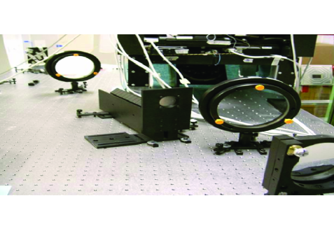
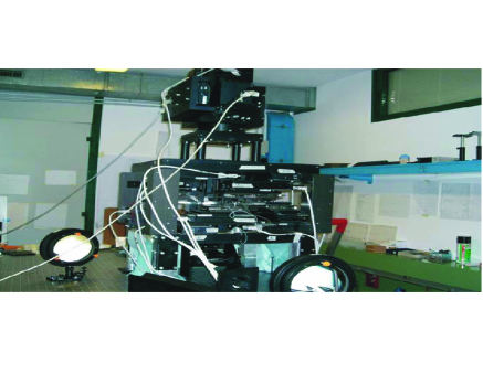
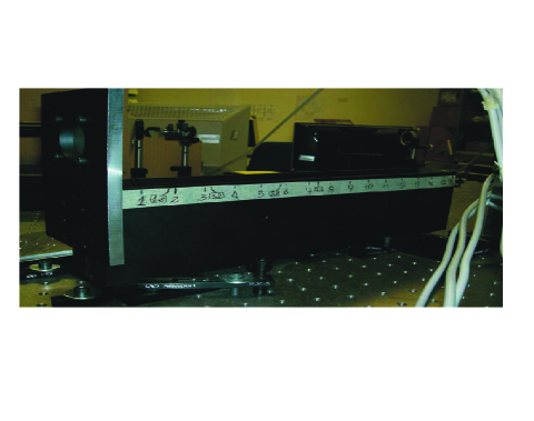
The telescope simulator intends to mimic the F/20 MAD focus at the LOWFS base positioned that, according to the opto-mechanical drawings, falls 10 mm above the mechanical base of the system (by drawings 4.35mm before the position of the star enlargers). At this plane is projected the 2 arcmin FoV seen by the sensor. In the alignment optical setup used the LOWFS base-plate stands on four legs to leave room below it for a mirror at 45 degrees with respect to the optical axis direction to fold this inside the LOWFS.
The experimental optical setup has been designed in a way similar to the system used to test the LO prototype[2]. It will allow testing, in open loop conditions, the stand-alone LOWFS by using white light emitted by a set of fibers and distorted by a set of perturbing screens to simulate the atmospheric turbulent layers.
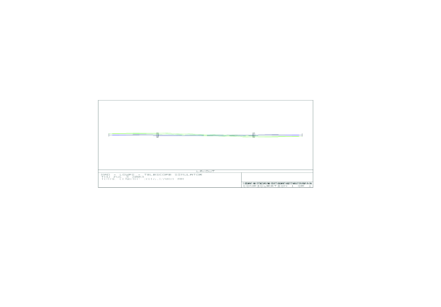
Two identical lenses spaced, by twice their focal length, and a stop pupil, in their common foci, compose the telescope simulator. A turbulent static screen mounting is arranged to place them on positions corresponding between 0 and 18km from the ground pupil.
Two lenses of 150mm diameter with a focal length of 793mm are used to mimic the telecentric beam. The optical axis flies parallel to the bench plane and it passes in the center of the stop pupil between the L1 and L2. It is a 40mm diaphragm on the same mounting of the static screens. The 40mm aperture defines the simulated telescope pupil and the F/20 angle, it is placed in focal plane of both the L1 and L2. The tip-tilt of the pupil is corrected in order to be orthogonal to the optical axis posing a flat mirror on the diaphragm. The positioning of the tip-tilt of the pupil is better than 20arcsec, while the precision in the height positioning of the pupil is better than 0.5 mm.
The optical fibers that mimic the star sources can be inserted on a large number of slots on a plate. This plate can be moved in z (the optical axis of the telescope simulator) using linear stage. The telescope simulator re-images a 1:1 copy of the reference object (the fiber plate); the 2arcmin FoV corresponds to a circular region of 94 mm diameter on the plate where the optical fiber can be arranged in several different configurations, to mimic different guide stars constellations.
The optical fibers used in the measurements presented in this document have a 50m core. They do not transmit an identical amount of light, so they were selected opportunely, according the test to be performed. Regarding the optical quality tests (see section2.1) the fiber core dimension does not affect the results because the spot dimension on the CCD is produced by the holes size in the mask placed at the pupil plane. Furthermore the dimension of an ideal source imagined in the LOWFS focal plane by the telescope simulator has 180m of diameter. However we checked that using fibers with different core sizes works such as using different modulation of the pyramids and that it changes the calibration factor that transforms WF measurements from arbitrary to real length units.
2.1 Telescope Simulator optical quality
The telescope simulator exhibits a number of potential departures from the optical system composing MAD. These are hereby listed and discussed:
-
•
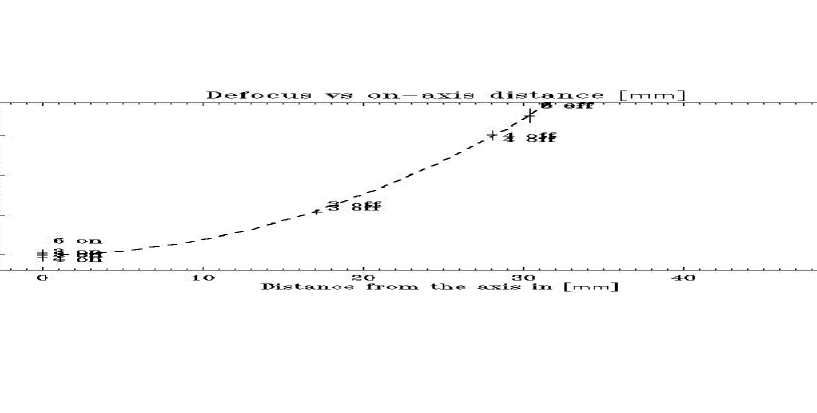
Field curvature. This is taken into account and corrected for by adjusting the fibers positions along the optical axis on the fiber-plate, when they are placed off-axis. The defocus measurement is made using the pyramid WF sensor embedded in the instrument and it achieves usually a quality better than about 40nm.
-
•
Telecentricity and final F/20 have been checked during the alignment procedure through auto-collimation in the pupil plane and it is well within the specifications of the MAD exit relay. According to the optical requirements for the input beam of the LOWFS an F/200.2 is requested and with a maximum non-telecentricity angle of 1.9arcmin. The final focal ratio (15F/20=F/300) has been checked looking to the dimension of the re-imaged pupils on the detectors: we measured 385m m to be compared with 388m (by the optical design). Moreover, considering that the star enlargers increase the total focal ratio by a factor 15, it is possible to obtain for the telescope simulator an F/200.2. For telecentricity has been reached a 1mm precision in the positioning of the lens L2 with respect to the pupil mask on the screens holder, which corresponds to an error of 50arcsec of non-telecentricity angle.
-
•
Chromatism is, by Zemax design, very small and negligible with respect to the one introduced by the pyramids. Recall that the telescope simulator is made up by a couple of achromatic doublets that introduce an overall blur of 1/50 of sub-aperture.
-
•
The residual aberration is mainly astigmatism of third order. This is not negligible and depends upon the position on the Field of View. However, to perform phase screens analysis a measurement of the static aberrations with for each guide stars constellation is performed and later subtracted from the WF measurements. This is somehow similar to the handling of non-common path aberrations as will be done on the MAD experiments, even if in this case we will manage them as reference slope with respect to which the MCAO loop will be closed.
3 Calibration of the LOWFS
The LOWFS has been calibrated in order to translate the differential illumination measurements of the 4 metapupils in terms of wavefront distortions measured in wavefront displacement units (nanometers).
To achieve this goal we move of a known quantity the fiber-plate along the optical axis using a linear stage, which axis was previously aligned to the optical axis (defined by the laser beam direction).
We use the formula:
| (1) |
this formula relates the Peak to Valley (PV) of the defocus aberration to the shift applied to the object on the focal plane along the optical axis. In our case d is the pupil diaphragm diameter (40 mm), is the focal length of the first lens (793 mm) and is the amount of shift to be read on the linear stage. The validity of this formula was checked using Ray-tracing both giving nm.
Experimentally was found the calibration coefficients to translate wave-fronts from arbitrary to nm units.
4 Pupil image optical quality
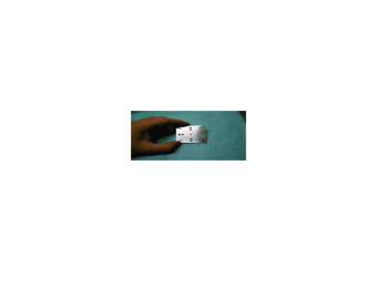
In order to check the optical quality of the WFS objectives we used a pupil mask with small holes (Figure 4) distributed on a cross over the 40mm circular aperture defining the telescope simulator pupil. The diameter of each spot has been fixed to 1/50 of the pupil size (0.8mm) to fit the dimension of the CCDs pixel size corresponding to 1/52 of the pupil diameter. In this way, and in pure geometrical approximation, the holes images present a dimension equivalent to one pixel, when the mask is placed on the pupil position. In fact one pixel is 7.4m while the image of the hole should be 7.7m. We measured the dimension of the spots using only one fiber source first on-axis and later off-axis. The image of the mask has been taken for each star enlarger (2 lenses and 1 pyramid). The fiber light source emits white light centred at 0.4m with a large spectrum. In order to avoid un-realistic chromatic-effect due especially to the pyramids the white light should be modulated in wavelength with a filter as close as possible to the final LOWFS spectral characteristics. Such a filter was not available and we checked how the measurements fit the theoretical previsions.
The fibers illuminator has a bandwidth of 0.25m to 0.80m with a 3250Kelvin colour temperature at the maximum intensity. The Electrim 1000N has a known spectrum response. In this test the two LO objectives are imaging an object (the 9 holes mask) positioned at the pupil (the ground) position. The pupil of the star enlarger + objective system is defined by the dimension of the second lens of the star enlarger (12.7 mm diameter) however it is not completely illuminated (only about 10 mm are effectively used). Considering the LOWFS-MAD central operation wavelength is 0.55m and the 115.7 mm objective focal length, the /D corresponds to a 6.4m FWHM. But the image chromatic elongation produced by the pyramidic prism overcomes the diffraction effect. In fact the divergence angle,, of the 4 beams exiting each pyramids depends on the diffraction index through the equation[5]:
| (2) |
where is the pyramid physical vertex angle (here 1.176 degrees) and n is the refraction index. In particular the pyramids are made of BK7 glass, which spectral behaviour is presented in Figure 5:
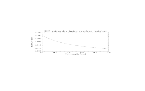
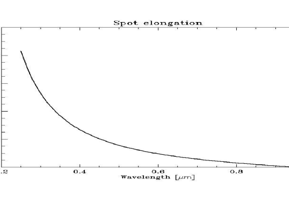
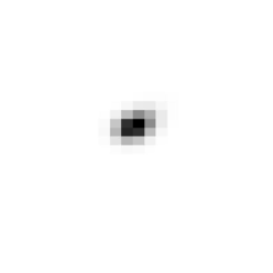
This refractive index variation produces a spot elongation, larger and larger as the bandwidth used increases (Figure 6 and Figure 7). Moreover the elongation directions are defined by the pyramid faces orthogonal planes, corresponding to the direction of the 4-pupils barycenter if projected on the CCD sensor
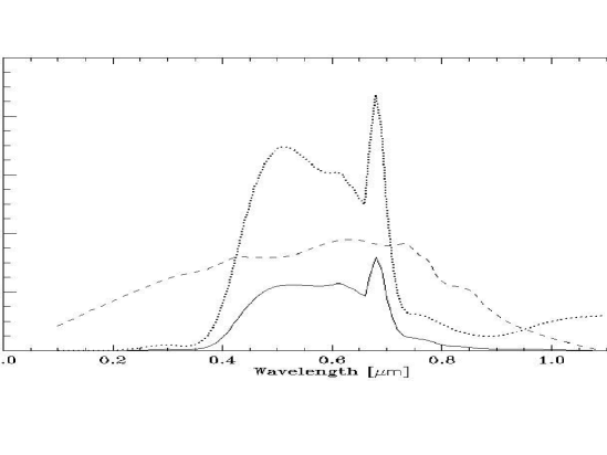
The fiber illuminator emits between 0.25m to 0.80m. To the wavelength range 0.31-0.80 corresponds a 45m elongation, equivalent to 6.2 Electrim pixels. But the emissivity function has not flat spectrum and should be multiplied for the Electrim quantum efficiency (QE) response function to have a realistic idea of the intensity distribution over the elongated spot. In order to check the matching of the measurements with the expected results, the latter has been computed with the QE (VS lambda) we have in the experimental setup. Please note, however, that this is rather flat in the range of interest.
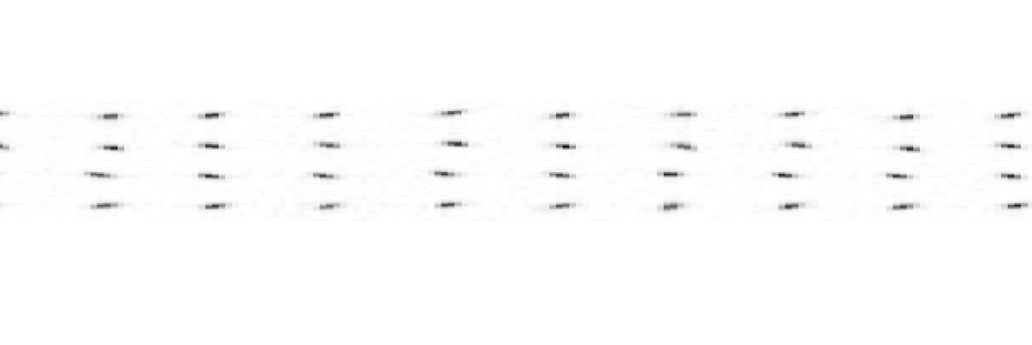
However, we have measured spot elongations with FWHM up to 24.9m that in a first order analysis gives a maximum elongation of about 50m. All the point spread functions (PSF) measured have been interpolated with 2 dimensional Gaussian functions. The fit took into account both ellipsoidal shape of the PSF and the axis rotation.
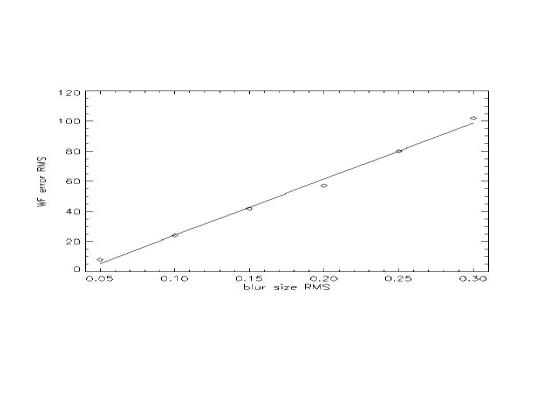
The spot rms computed fitting the measurements data of the PSFs is 8.04m with an rms of 0.58m equivalent to 0.167 ground sub-apertures (1sub = 48 m) equivalent to 52nm WFE according to the Wavefront Error Budget analysis performed so far[6] (Figure 9). In fact the blur of the pupil images due to mis-alignment, chromatism, dirty optics, etc.., introduce a loss of information in the WF/slope reconstruction, we quantified this effect through numerical simulation and it can be described such as a linear relation between blur of the pupil image and residual phase rms in closed loop operation that exceeds with respect to the ideal case with no blur.
In the instrument requirements was given for the chromatism effect a 57nm rms Wave-Front-Error to be compared to 52nm we have measured in the setup used. This error corresponds to an equivalent spot rms of 0.15 sub-apertures (compared to 0.207). But we saw that elongation effect depends on the waveband used. In particular we have to compare the 7.9m spot rms measure to the elongation spot due to the system effectively mounted on the bench. The quantum efficiency of the system illuminator and Electrim 1000N was computed (using technical data-sheets) and the effective spot elongation simulated.
| Average m | m | Average sub-aper | sub-aper | |
|---|---|---|---|---|
| LOWFS1 “Ground” | 7.99 | 0.39 | 0.166 | 0.008 |
| LOWFS2 “High” | 8.00 | 0.49 | 0.167 | 0.010 |
The final LOWFS system will have a similar chromatic answer and then similar elongation spot sizes. More detail about specifications on the pyramid vertex angle and measurements can be found in the cited paper[7].
5 Layer Smoothing at different altitudes
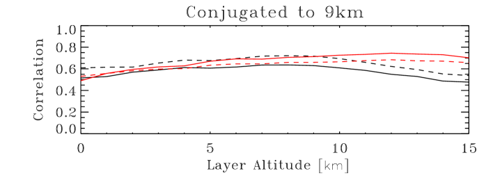
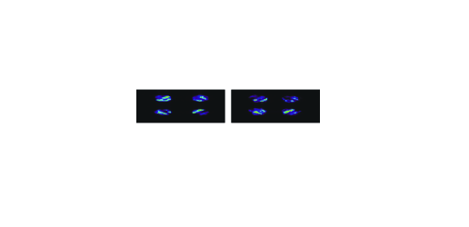
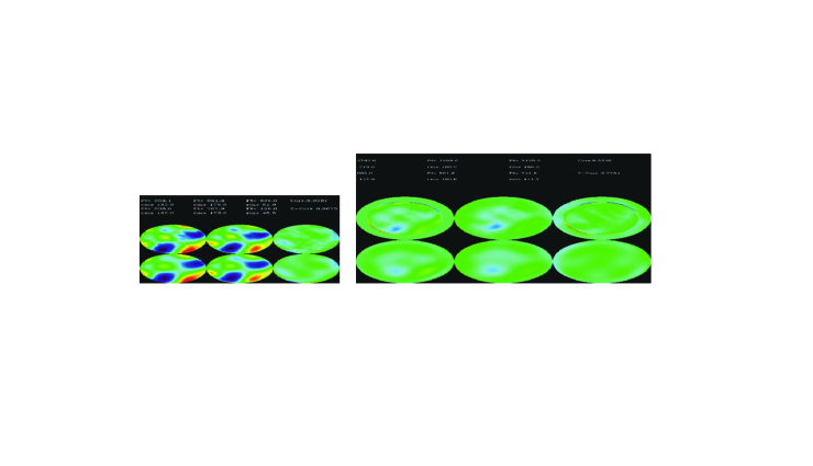
We verified that the LOWFS is able to measure the turbulence at the conjugated altitude and in an atmospheric volume close to that plane. But the non-conjugated layers are seen more and more smoothed as the distance from the conjugation plane increases. To check this statement a single plastic screen has been measured with an interferometer and then placed in 16 different positions corresponding to altitude between 0 and 15 km, 1 km spaced, (Figure 10). The two objectives had been previously conjugated to 0 (LOWFS1) and 9 km (LOWFS2). For this test 3 and 8 different fiber-reference sources have been used positioned in a restricted FoV of 1arcmin for the case with 3 stars and over the full 2arcmin for the case with 8 stars. The interferometric measurements of the plastic screen aberration refer only to a 50.8 mm pupil, to be compared to the 66.2mm size of the metapupil at 9 km. In the comparison we had not considered the outer region of the LOWFS measurements. For both WFS a couple of 4 meta-pupils image with slightly different tip-tilt have been taken (introduced de-centring the pyramid optical axis using the XY linear stages to simulate a tip-tilt modulation).
A posteriori the static WFs have been removed from the phase measurements. Results and comments are in the picture captions.
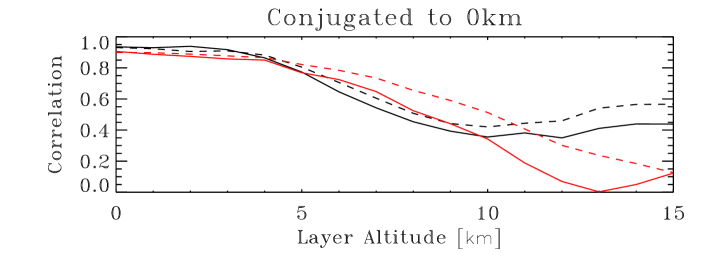
6 Scanning the atmosphere
In this test we verified how the ground and high WFS measurements are still correlated when screen at different altitudes are inserted. In particular we first place a screen at 0km, and then we added a screen at 9 km and finally at 4km. Then we removed, in this order, the 4km and the 0 km screen. For each of this configuration ground and high conjugation plane (9 km) have been retrieved.
7 Conclusions
In this paper we show rapidly the more interesting topic related to the alignment of the LOWFS for MAD. We described how this had been reached and a few indicator of the quality achieved, such as the pupil optical quality. Finally we presented several results to show the ability of the LOWFS to measure WF both in classical Adaptive Optics and MCAO modes comparing plastic screen WF measurement to the ones performed by an interferometer. This comparison gives very high correlations especially with low strength turbulence, a behavior already predicted by pyramids WFS models. In fact it is known how pyramid WF gives best performance in closed loop operation rather than open loop one (such as the cases we had in experimental setup without deformable mirrors).
![[Uncaptioned image]](/html/0912.0879/assets/x17.png)
References
- [1] Ragazzoni, R., Farinato, J., and Marchetti, E., “Adaptive optics for 100-m-class telescopes: new challenges require new solutions,” in [Adaptive Optical Systems Technology ], Wizinowich, P. L., ed., Proc. SPIE 4007, 1076–1087 (2000).
- [2] Farinato, J., Ragazzoni, R., Arcidiacono, C., Paolo, B., Baruffolo, A., Baumeister, H., Bisson, R., Bohnhardt, H., Brindisi, A., Brynnel, J., Cecconi, M., Coyne, J., Delabre, B., Diolaiti, E., Donaldson, R., Fedrigo, E., Franza, F., Gassler, W., Ghedina, A., Herbst, T. M., Hubin, N. N., Kellner, S., Kolb, J., Lizon, J.-L., Lombini, M., Marchetti, E., Meneghini, G., Mohr, L., Reiss, R., Rohloff, R.-R., Soci, R., Vernet, E., Weiss, R., Xompero, M., and Xu, W., “Layer-Oriented on paper, laboratory, and soon on the sky,” in [Second Backaskog Workshop on Extremely Large Telescopes. ], Ardeberg, A. L. and Andersen, T., eds., Proc. SPIE 5382, 578–587 (2004).
- [3] Ragazzoni, R., Diolaiti, E., Vernet, E., Farinato, J., Marchetti, E., and Arcidiacono, C., “Arbitrarily Small Pupils in Layer-Oriented Multi-Conjugate Adaptive Optics,” PASP 117, 860–869 (2005).
- [4] Vernet-Viard, E., Arcidiacono, C., Bagnara, P., Baruffolo, A., Diolaiti, E., Farinato, J., Lombini, M., and Ragazzoni, R., “Layer-oriented wavefront sensor for a multiconjugate adaptive optics demonstrator,” Optical Engineering 44(9), 096601 (2005).
- [5] Esposito, S., Tozzi, A., Ferruzzi, D., Carbillet, M., Riccardi, A., Fini, L., Vérinaud, C., Accardo, M., Brusa, G., Gallieni, D., Biasi, R., Baffa, C., Biliotti, V., Foppiani, I., Puglisi, A., Ragazzoni, R., Ranfagni, P., Stefanini, P., Salinari, P., Seifert, W., and Storm, J., “First Light Adaptive Optics System for Large Binocular Telescope,” in [Adaptive Optical System Technologies II ], P. L. Wizinowich & D. Bonaccini, ed., Proc. SPIE 4839, 164–173 (2003).
- [6] Arcidiacono, C., Diolaiti, E., Ragazzoni, R., Viard, E., Farinato, J., and Baruffolo, A., [Layer Oriented Wavefront Sensor for MAD Final Design Review: System Design Analysis ], ESO (2003).
- [7] Arcidiacono, C., “Beam divergence and vertex angle measurements for refractive pyramids,” Optics Communications 252, 239–246 (2005).